Sign In
Upload
Download
Table of Contents
Contents
Add to my manuals
Delete from my manuals
Share
URL of this page:
HTML Link:
Bookmark this page
Add
Manual will be automatically added to "My Manuals"
Print this page
×
Bookmark added
×
Added to my manuals
Manuals
Brands
Bang & Olufsen Manuals
Speakers
BeoLab 7-1
Service manual
Bang & Olufsen BeoLab 7-1 Service Manual
Hide thumbs
Also See for BeoLab 7-1
:
User manual
,
Service manual
(28 pages)
,
Manual
(12 pages)
1
2
Table Of Contents
3
4
5
6
7
8
9
10
11
12
13
14
15
16
17
18
19
20
21
22
23
24
page
of
24
Go
/
24
Contents
Table of Contents
Bookmarks
Advertisement
Table of Contents
1
Table of Contents
2
How to Service
3
Repair Tips
4
Replacement of Spare Parts
5
Adjustments
6
Final Check after Repair
7
Illustrations
8
Specification Guide Lines
9
Overall Block Diagram
10
Wiring Diagram
11
Available Parts
Download this manual
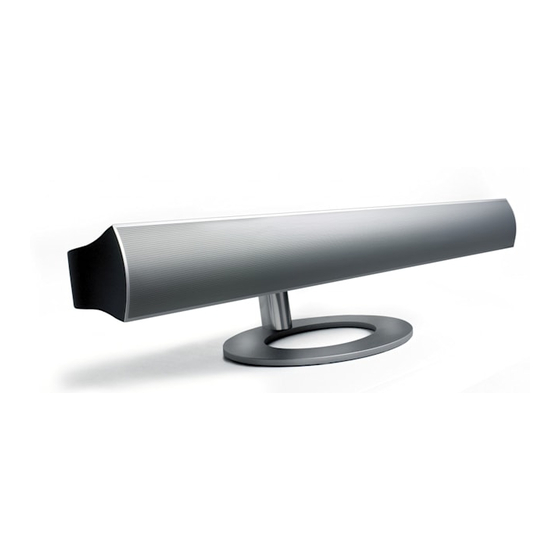
BeoLab 7 – 1
Type 6210, 6212
Service Manual
English
German, French, Italian, Spanish, Danish and Dutch versions
are available in the Retail System
This Service Center repair guide must be
returned with the defective parts/back-up
suitcase !
Table of
Contents
Previous
Page
Next
Page
1
2
3
4
5
Advertisement
Table of Contents
Need help?
Do you have a question about the BeoLab 7-1 and is the answer not in the manual?
Ask a question
Questions and answers
Related Manuals for Bang & Olufsen BeoLab 7-1
Speakers Bang & Olufsen beolab 7-1 Service Manual
(28 pages)
Speakers Bang & Olufsen BeoLab 7-1 Manual
(12 pages)
Speakers Bang & Olufsen BeoLab 7-1 User Manual
Bang & olufsen beolab 7-1: user guide (12 pages)
Bang & Olufsen BeoLab 7-1 - Loudspeaker Manual
(article)
Speakers Bang & Olufsen BeoLab 7-4 User Manual
Bang & olufsen beolab 7-4: user guide (12 pages)
Bang & Olufsen BeoLab 7-4 - Loudspeaker Manual
(article)
Speakers Bang & Olufsen BeoLab 7-2 Manual
(12 pages)
Speakers Bang & Olufsen BeoLab 7-6 User Manual
(12 pages)
Speakers Bang & Olufsen BeoLab 2 Manual
Bang & olufsen beolab 2: user guide (13 pages)
Speakers Bang & Olufsen BeoLab 3 6881 Service Center Manual
(31 pages)
Bang & Olufsen BeoLab 17 - Speakers Manual
(article)
Speakers BANG & OLUFSEN BEOLAB 3500 Manual
All-in-one (28 pages)
Speakers Bang & Olufsen BeoLab 4000 User Manual
Bang & olufsen beolab 4000: user guide (12 pages)
Speakers Bang & Olufsen BeoLab 9 6217 Service Manual
(40 pages)
Speakers Bang & Olufsen Beolit 12 Manual
(68 pages)
Speakers Bang & Olufsen Beolit 12 Manual
(2 pages)
This manual is also suitable for:
6210
6212
Table of Contents
Print
Rename the bookmark
Delete bookmark?
Delete from my manuals?
Login
Sign In
OR
Sign in with Facebook
Sign in with Google
Upload manual
Upload from disk
Upload from URL


Need help?
Do you have a question about the BeoLab 7-1 and is the answer not in the manual?
Questions and answers