Table of Contents
Advertisement
Quick Links
L-Band/Wideband Standalone Fiber Receiver
© Copyright 2016
EVERTZ MICROSYSTEMS LTD.
5292 John Lucas Drive
Burlington, Ontario
Canada L7L 5Z9
Phone:
905-335-3700
Sales:
sales@evertz.com
Tech Support: service@evertz.com
Web Page:
http://www.evertz.com
Version 1.0, December 2016
The material contained in this manual consists of information that is the property of Evertz Microsystems and is intended solely for the use of
purchasers of the 2406LR products. Evertz Microsystems expressly prohibits the use of this manual for any purpose other than the operation of
the 2406LR product. Due to on going research and development, features and specifications in this manual are subject to change without notice.
All rights reserved. No part of this publication may be reproduced without the express written permission of Evertz Microsystems Ltd. Copies of
this manual can be ordered from your Evertz dealer or from Evertz Microsystems.
2406LR
User Manual
Fax: 905-335-3573
Fax: 905-335-7571
Advertisement
Table of Contents

Related Manuals for evertz 2406LR


Summary of Contents for evertz 2406LR
- Page 1 Version 1.0, December 2016 The material contained in this manual consists of information that is the property of Evertz Microsystems and is intended solely for the use of purchasers of the 2406LR products. Evertz Microsystems expressly prohibits the use of this manual for any purpose other than the operation of the 2406LR product.
- Page 2 This page left intentionally blank...
- Page 3 IMPORTANT SAFETY INSTRUCTIONS The lightning flash with arrowhead symbol within an equilateral triangle is intended to alert the user to the presence of uninsulated “Dangerous voltage” within the product’s enclosure that may be of sufficient magnitude to constitute a risk of electric shock to persons. The exclamation point within an equilateral triangle is intended to alert the user to the presence of important operating and maintenance (Servicing) instructions in the literature accompanying the product.
- Page 4 WARNING Changes or Modifications not expressly approved by Evertz Microsystems Ltd. could void the user’s authority to operate the equipment. Use of unshielded plugs or cables may cause radiation interference. Properly shielded interface cables...
-
Page 5: Table Of Contents
2406LR L-Band/Wideband Standalone Fiber Receiver TABLE OF CONTENTS OVERVIEW ........................... 1 INSTALLATION ..........................3 2.1. 2406LR CONNECTIONS ...................... 3 2.2. CARE AND HANDLING OF OPTICAL FIBER ..............4 2.2.1. Safety ........................4 2.2.2. Assembly ........................4 2.2.3. Labeling ........................4 2.2.4. - Page 6 Figures Figure 1-1: 2406LR Block Diagram ........................2 Figure 2-1: 2406LR Module ..........................3 Figure 2-3: Reproduction of 2406LR Certification and Identification Label for Models that are Class 1 Laser Products ................................4 TABLES Table 5-1: Output Level Adjust Switch ......................11 Page - ii Revision 1.0...
- Page 7 Evertz products are for informational use only and are not warranties of future performance, either expressed or implied. The only warranty offered by Evertz in relation to this product is the Evertz standard limited warranty, stated in the sales contract or order confirmation form.
- Page 8 2406LR L-Band/Wideband Standalone Fiber Receiver This page left intentionally blank Page - iv Revision 1.0...
-
Page 9: Overview
Manual gain mode allows a fixed gain level to be applied to the output signal. AGC mode allows the user to set a target output level, and the 2406LR’s microprocessor will automatically apply the correct amount of gain to maintain that level. - Page 10 2406LR L-Band/Wideband Standalone Fiber Receiver Figure 1-1: 2406LR Block Diagram Page - 2 Revision 1.0...
-
Page 11: Installation
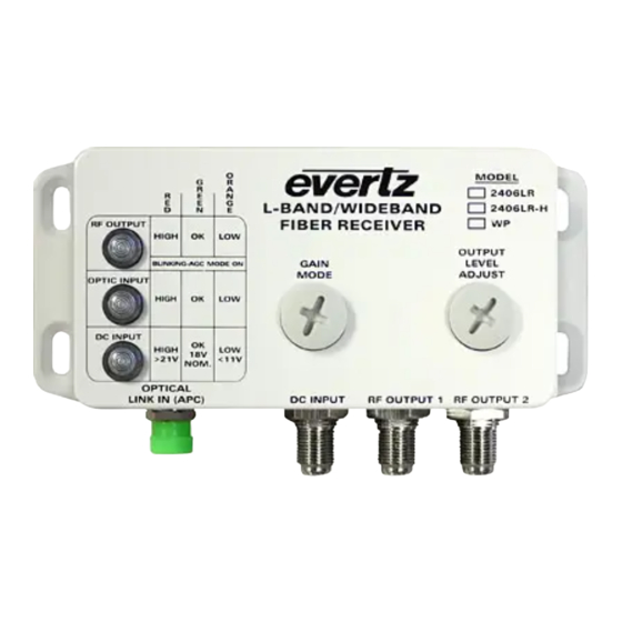
L-Band/Wideband Standalone Fiber Receiver INSTALLATION The 2406LR comes in a die cast enclosure with integral mounting flanges. It is recommended that the enclosure be mounted on a flat surface with the connectors facing down. For units with the -WP option exposed to the elements, while not required to prevent water ingress into the unit, good outdoor installation practice suggests the use of waterproof connectors, boots and/or protecting connectors with a wrap of Scotch 130C rubber tape followed by Scotch Super 88 vinyl tape, or equivalent. -
Page 12: Care And Handling Of Optical Fiber
Background colour: yellow Triangular band: black Symbol: black 2.2.2. Assembly Assembly or repair of the laser sub-module is done only at Evertz facility and performed only by Evertz technical personnel. 2.2.3. Labeling Certification and Identification labels are combined into one label. -
Page 13: Handling And Connecting Fibers
Evertz recommends that the user maintain a minimum bending radius of 5 cm to avoid fiber-bending loss that will decrease the maximum attainable distance of the fiber cable. - Page 14 2406LR L-Band/Wideband Standalone Fiber Receiver This page left intentionally blank Page - 6 Revision 1.0...
-
Page 15: 06Lr Specifications
2406LR L-Band/Wideband Standalone Fiber Receiver 2406LR SPECIFICATIONS 3.1. RF OUTPUTS Number of Outputs: F-type (50Ω BNC optional) Connector: Conductor Range: 23-18 AWG (0.26-0.82 mm 75Ω (50Ω optional) I/O Impedance: Frequency Range: 2406LR: 120MHz – 3GHz 2406LR-H: 120MHz – 2.3GHz Return Loss: 120MHz to 2.3GHz:... - Page 16 2406LR L-Band/Wideband Standalone Fiber Receiver This page left intentionally blank Page - 8 Revision 1.0...
-
Page 17: Status Indicators
2406LR L-Band/Wideband Standalone Fiber Receiver STATUS INDICATORS The 2406LR module has three LED status indicators on the front of the box to show operational status of the module at a glance. 4.1. RF OUTPUT INDICATOR In Manual Mode HIGH: The RF DRIVE LED will be RED when the incoming RF signal plus the module gain is over -5dBm and is overdriving the laser. -
Page 18: Optic Input Indicator
2406LR L-Band/Wideband Standalone Fiber Receiver 4.2. OPTIC INPUT INDICATOR For 2406LR HIGH: This indicator will be RED if the optical input gain is over 3dBm. This indicator will be GREEN if the optical input gain is between -14dBm and 3dBm. -
Page 19: User Controls
Note: Selecting Gain Modes other than 0 and 1 on the rotary dial will cause a misconfiguration. AGC will maintain the output of the 2406LR at a constant level even if the input signal level changes, but remains within the AGC hold range. - Page 20 2406LR L-Band/Wideband Standalone Fiber Receiver This page left intentionally blank Page - 12 Revision 1.0...