Table of Contents
Advertisement
Quick Links
© Copyright 2009
EVERTZ MICROSYSTEMS LTD.
5288 John Lucas Drive,
Burlington, Ontario,
Canada L7L 5Z9
Phone:
905-335-3700
Sales:
sales@evertz.com
Tech Support: service@evertz.com
Web Page:
http://www.evertz.com
Version 1.2 November 2009
The material contained in this manual consists of information that is the property of Evertz Microsystems and is
intended solely for the use of purchasers of the 2408RGBR/DVIR. Evertz Microsystems expressly prohibits the
use of this manual for any purpose other than the operation of the 2408RGBR/DVIR.
All rights reserved. No part of this publication may be reproduced without the express written permission of
Evertz Microsystems Ltd.
Microsystems.
2408RGBR/DVIR
DVI and RGB Video/Audio
Portable SFP Fiber Receiver
Instruction Manual
Fax: 905-335-3573
Fax: 905-335-7571
Copies of this manual can be ordered from your Evertz dealer or from Evertz
Advertisement
Table of Contents

Subscribe to Our Youtube Channel
Related Manuals for evertz 2408RGBR/DVIR


Summary of Contents for evertz 2408RGBR/DVIR
- Page 1 Version 1.2 November 2009 The material contained in this manual consists of information that is the property of Evertz Microsystems and is intended solely for the use of purchasers of the 2408RGBR/DVIR. Evertz Microsystems expressly prohibits the use of this manual for any purpose other than the operation of the 2408RGBR/DVIR.
- Page 2 This page left intentionally blank...
- Page 3 IMPORTANT SAFETY INSTRUCTIONS The lightning flash with arrowhead symbol within an equilateral triangle is intended to alert the user to the presence of uninsulated “Dangerous voltage” within the product’s enclosure that may be of sufficient magnitude to constitute a risk of electric shock to persons. The exclamation point within an equilateral triangle is intended to alert the user to the presence of important operating and maintenance (Servicing) instructions in the literature accompanying the product.
- Page 4 WARNING Changes or Modifications not expressly approved by Evertz Microsystems Ltd. could void the user’s authority to operate the equipment. Use of unshielded plugs or cables may cause radiation interference. Properly shielded interface cables...
-
Page 5: Table Of Contents
2408RGBR/DVIR DVI & RGB Video/Audio Portable SFP Fiber Receiver TABLE OF CONTENTS OVERVIEW............................1 INSTALLATION........................... 3 2.1. OPTICAL CONNECTIONS......................5 2.2. SIGNAL CONNECTIONS ......................5 2.3. INTERFACING WITH 3G OPTICAL ROUTER................6 2.4. CARE AND HANDLING OF OPTICAL FIBER................6 2.4.1. - Page 6 2408RGBR/DVIR DVI & RGB Video/Audio Portable SFP Fiber Receiver 4.4.1. Card-Edge Display Warning Indications................ 14 4.4.2. Selecting the Output Sync Type (2408RGBR Models Only) ......... 14 4.4.3. Adjusting the Horizontal and Vertical Shift (2408RGBR Models Only) ......14 4.4.4. Setting the Link Rate ..................... 15 4.4.5.
- Page 7 Nov 09 Information contained in this manual is believed to be accurate and reliable. However, Evertz assumes no responsibility for the use thereof nor for the rights of third parties, which may be affected in any way by the use thereof. Any representations in this document concerning performance of Evertz products are for informational use only and are not warranties of future performance, either expressed or implied.
- Page 8 2408RGBR/DVIR DVI & RGB Video/Audio Portable SFP Fiber Receiver WARNING Never look directly into an optical fiber. Non-reversible damage to the eye can occur in a matter of milliseconds. Page iv Revision 1.2...
-
Page 9: Overview
Monitoring and control of card status and card parameters are provided locally at the card-edge, or remotely via VistaLINK capability. ® The 2408RGBR/DVIR uses Evertz SFP modules to interface to and from the fiber optic domain. SFP receivers and transceivers have wide-band optical input and can accept any wavelength between 1270nm and 1610nm. Features: •... -
Page 10: Figure 1-1: 2408Rgbr Block Diagram
2408RGBR/DVIR DVI & RGB Video/Audio Portable SFP Fiber Receiver DVI/RGB out Optical Input Evertz SFP 2 Stereo Pair Receiver or Analog Audio Tranceiver +A2 version TX/RX Interface DB-9 Serial Optical Output Keyboard Mouse Control / Indication +A2KM-USB version VistaLINK Figure 1-1: 2408RGBR Block Diagram... -
Page 11: Installation
The following diagrams show all rear plate options for the 2408RGBR/DVIR. When installing the Evertz SFP module into the rear plate SFP housing, align the transmit and receive arrow indicators UPWARD with the 2408RGBR module upright. Gently slide the SFP module into the rear plate SFP housing until it clicks into place. -
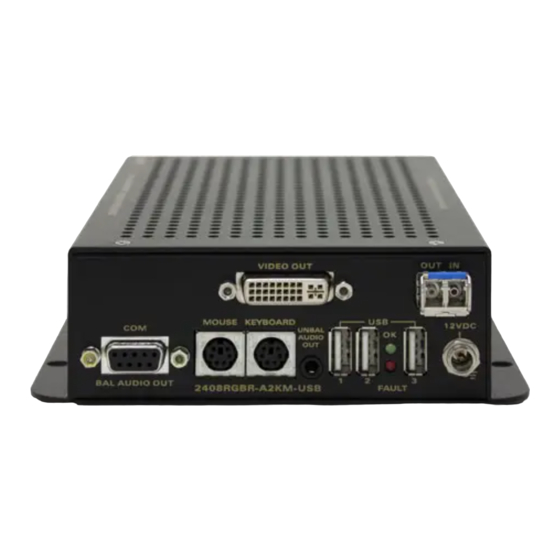
Page 12: Figure 2-1: 2408Rgbr & 2408Dvir Rear Panels
2408RGBR/DVIR DVI & RGB Video/Audio Portable SFP Fiber Receiver Figure 2-1: 2408RGBR & 2408DVIR Rear Panels Page - 4 Revision 1.2... -
Page 13: Optical Connections
SFP FIBER INPUT: There is one LC/PC female connector when the 2408RGBR/DVIR is equipped with an Evertz Receiver or Transceiver SFP module. This wide band optical input accepts optical wavelengths of 1270nm to 1610nm, accommodating standard or CWDM transmission schemes. -
Page 14: Interfacing With 3G Optical Router
CLASS 1 LASER PRODUCT Background colour: yellow Triangular band: black Symbol: black 2.4.2. Assembly Assembly or repair of the laser sub-module is done only at Evertz facility and performed only by qualified Evertz technical personnel. Page - 6 Revision 1.2... -
Page 15: Labeling
Printed circuit board of each Evertz plug-in module. • The Model number is one of: 2408RGBR/DVIR, 2408RGBR/DVIR-A2, 2408RGBR/DVIR-A2KM- USB+13, 2408RGBR/DVIR-A2KM-USB+Cxx (xx = 27, 29, 31, 33, 35, 37, 43, 45, 47, 49, 51, 53, 55, 57, 59, 61) Figure 2-3: Reproduction of Laser Certification and Identification Label 2.4.4. -
Page 16: Specifications
2408RGBR/DVIR DVI & RGB Video/Audio Portable SFP Fiber Receiver SPECIFICATIONS 3.1. ANALOG VIDEO OUTPUTS Number of Signals: Signal Type: Sync Type: H and V, or Sync on Green Connector: DVI-1 with Analog, or 15-pin HD-15 VGA Analog (with adapter) Display Resolution:... -
Page 17: Keyboard/Mouse Input/Output (A2Km-Usb Versions)
2408RGBR/DVIR DVI & RGB Video/Audio Portable SFP Fiber Receiver 3.5. KEYBOARD/MOUSE INPUT/OUTPUT (A2KM-USB VERSIONS) Number: Connector: 1 PS2 each for keyboard and mouse 3.6. SERIAL PORT (A2KM-USB VERSIONS) Standard: RS232 or RS422 (user selectable) Number: Connector: DB9M 3.7. USB PORT (A2KM-USB VERSIONS) Standard: USB 2.0... -
Page 18: Card-Edge Monitoring And Control
2408RGBR/DVIR DVI & RGB Video/Audio Portable SFP Fiber Receiver CARD-EDGE MONITORING AND CONTROL 4.1. ACCESSING THE TOGGLE SWITCH AND PUSH BUTTON To expose the card edge controls you must remove the side panel. To do so, follow the instructions listed below: 1. -
Page 19: Card Edge Operation
4.2. CARD EDGE OPERATION The 2408RGBR/DVIR has nine LED status indicators and a 4-digit dot-matrix display on the front card- edge to show operational status of the card at a glance. The card-edge pushbutton and toggle switch are used to select various control and status indications to the dot-matrix display. Additionally, an audio monitoring headphone jack is provided at the card-edge, for verification of signal presence and content. -
Page 20: Status Indicator Leds
2408RGBR/DVIR DVI & RGB Video/Audio Portable SFP Fiber Receiver 4.3. STATUS INDICATOR LEDS LOCAL FAULT: This red LED indicates poor module health. Several conditions could cause this fault indication to be active: o A link with a companion 2408RGBT/DVIT has not been achieved o A card power fault exists (i.e. -
Page 21: Figure 4-5: 2408Rgbr Card Edge Menu Flow Cart
2408RGBR/DVIR DVI & RGB Video/Audio Portable SFP Fiber Receiver Level 1 Level 2 Level 3 Level 4 NOTES BACK BACK AUTO OSNC HSFT -10 to +10 VSFT -10 to +10 2970 LINK 3125 0 to 63 NORM BLAK OSET CTRL... -
Page 22: Card-Edge Display Warning Indications
2408RGBR/DVIR DVI & RGB Video/Audio Portable SFP Fiber Receiver 4.4.1. Card-Edge Display Warning Indications There are flashing warning indications that might appear on the display of the 2408RGBR/DVIR. These warning indications can overwrite other display text, and supersede each other by order of priority. By pressing the pushbutton, a warning indication can be cleared from the display, and access to other menu items is maintained. -
Page 23: Setting The Link Rate
2408RGBR/DVIR DVI & RGB Video/Audio Portable SFP Fiber Receiver 4.4.4. Setting the Link Rate In applications with 3G routing, the Link Rate of the 2408RGBR/DVIR must be 2970Mb/s to be compatible with 3G routers. Two user selectable Link Rates may be chosen, 2970Mb/s for routing purposes and 3125Mb/s for normal operation. -
Page 24: Adjusting The Output On Loss
4.4.8. Selecting the Output Laser Enable Mode (A2KM-USB Version) In some applications, it is beneficial to disable the laser output with no input signal present. Alternatively, it may be preferable to maintain an optical output signal, even with no input. The 2408RGBR/DVIR supports both modes of operation. -
Page 25: Adjusting The Headphone Jack Volume (A2 & A2Km-Usb Versions)
4.4.10. Adjusting the Headphone Jack Volume (A2 & A2KM-USB Versions) The 2408RGBR/DVIR provides a convenient audio monitoring headphone jack at the card-edge. This jack can be used to verify signal presence or content for each audio channel. The headphone jack volume can be adjusted via the card-edge interface. -
Page 26: Displaying The Connected Display Type (2408Rgbr Models Only)
Sync signal at the RGBT input is Sync On Green Sync signal at the RGBT input is RGB H and V 4.4.15. Displaying the Input Optical Power The 2408RGBR/DVIR can measure and display optical power over a range of –40 to 0dBm in 1dBm increments. STAT To display the Optical Power, select the STAT menu item in the first menu level. -
Page 27: Displaying The Link Rate
Link Rate set to 3125Mb/s for normal operation. 3125 4.4.17. Displaying the Transmitter ID Tag The 2408RGBR/DVIR can display the ID Tag of the fiber connected 2408RGBT/DVIT. STAT To display the 2408RGBT/DVIT ID Tag, select the STAT menu item in menu level 1. -
Page 28: Jumper Controls
2408RGBR/DVIR DVI & RGB Video/Audio Portable SFP Fiber Receiver JUMPER CONTROLS Several jumpers, located at the front of the module are used to preset various operating modes. Figure 4-4 shows the locations of the jumpers. 5.1. CONFIGURING THE MODULE FOR FIRMWARE UPGRADES... -
Page 29: Vistalink ® Remote Monitoring/Control
(GUI), third party or custom manager software may be used to monitor and control Evertz VistaLINK enabled fiber optic products. ® 2. Managed devices (such as 2408RGBR/DVIR cards), each with a unique address (OID), communicate with the NMS through an SNMP Agent. Evertz VistaLINK enabled 7700 series modules reside in the ®... -
Page 30: Monitored Parameters
2408RGBR/DVIR DVI & RGB Video/Audio Portable SFP Fiber Receiver 6.2. VISTALINK MONITORED PARAMETERS ® The following parameters can be remotely monitored through the VistaLINK interface. ® Parameter Name Description Input video resolution Input Video Resolution Input Type Input Type Optical Power... -
Page 31: Vlink Traps
2408RGBR/DVIR DVI & RGB Video/Audio Portable SFP Fiber Receiver 6.4. LINK TRAPS ISTA ® The following traps can be VistaLINK enabled and monitored. ® Trap Description Input Present Triggers when valid optical input is lost Optical Link Triggers when valid optical link is lost... - Page 32 2408RGBR/DVIR DVI & RGB Video/Audio Portable SFP Fiber Receiver This page left intentionally blank Page - 24 Revision 1.2...
Need help?
Do you have a question about the 2408RGBR/DVIR and is the answer not in the manual?
Questions and answers