London Electronics FUSION-P Manual
Large digit scalable process meter 4 digit version
Hide thumbs
Also See for FUSION-P:
- Installation & operating manual (44 pages) ,
- Installation & operating manual (44 pages)
Advertisement
Quick Links
London Electronics Limited
Warren Court, Chicksands, Shefford, Bedfordshire SG17 5QB
Tel +44(0)1462-850967
Fax +44(0)1462-850968
www.london-electronics.com help@london-electronics.com
Large digit scalable process meter
FUSION-P 4 digit version
Connection details, scaling and general information
Caution: There is a risk of electrical
shock if this instrument is not properly installed
Caution: Risk of danger: Read the whole
!
manual before you install this meter
Software version F00.12
1
Document Ref:pm65\manuals\Fusion_P
Revision:8 Dated: 31 October 2008
Advertisement

Related Manuals for London Electronics FUSION-P


Summary of Contents for London Electronics FUSION-P
- Page 1 Tel +44(0)1462-850967 Fax +44(0)1462-850968 www.london-electronics.com help@london-electronics.com Large digit scalable process meter FUSION-P 4 digit version Connection details, scaling and general information Caution: There is a risk of electrical shock if this instrument is not properly installed Caution: Risk of danger: Read the whole manual before you install this meter Software version F00.12...
- Page 3 Contents Alarm board configuration Alarm programming 26-31 Analogue output 23-24 Bootup routine Brightness Adjustment Button Functions 12-13 Calibration - introduction Calibration method - direct, no linearisation Calibration method - direct, with linearisation Calibration method - theoretical, no linearisation 16-17 Calibration method - theoretical, with linearisation Connections Decalaration of conformity General Description...
- Page 4 Warnings Please carefully read this manual and all warnings. Install the display ONLY when you are sure that you’ve covered all aspects. Check that the model number and supply voltage suit your application before you install the display. Connect the display according to current IEE regulations, IEC61010 & NFPA:70 National Electric Code in USA.
- Page 5 Introduction Please contact us if you need help, if you have a complaint, or if you have suggestions to help us improve our products or services. If you contact us about a product you already have, please tell us the full model number and serial number, so that we can give you accurate and fast help.
- Page 6 General Description The FUSION Series of displays accept industrial sensors to allow various physical measurements to be made, such a weight, temperature, pressure, humidity etc. Different models are available for different sensor types. The main function of the FUSION series is to give a large numeric readout of the variable being monitored.
- Page 7 Mounting and Installation Install your Fusion display according to local electrical regulations. Mount it away from moving machinery, to minimise the chance of damage, and keep away from sources of heat, plastics solvents and electrical and magnetic noise, such as welding equipment, arc lighting, inductive machines etc. The screws on the back of the display are necessary for sealing - do not omit any screws.
- Page 8 Wiring Advice Only open the case when power has been removed. This display uses internal detachable screw terminal connectors. Refer to the wiring diagram on the following page for the correct positioning of each wire. Each cable is fed through a compression gland for sealing. All glands must be sealed, unused glands must be plugged.
- Page 9 Connections DC+/AC L DC- / AC N Earth Contact closure Sensor Inputs logic Power...
- Page 10 Startup meter Settings Lockout notes: Cal Lock switch = OFF when changing. Switch Cal Lock to ON after changing Menu Language Choice Press the two right hand buttons briefly. You will see the User Interface language, which you can change with the UP or DOWN buttons. Accept with OK L.EnG L.FRA Next you will see ...
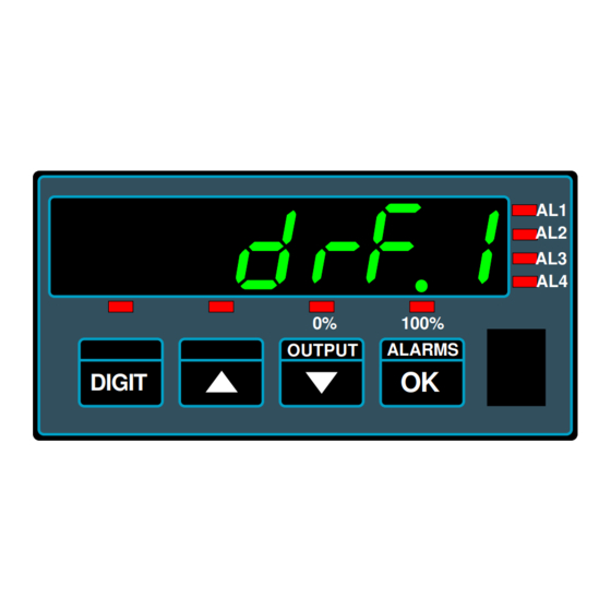
- Page 11 Drift cancellation (Not on INT2-C, INT2-S) drf.0 drf.0 If your meter will normally be showing 0, for example a platform scale, you can set the meter to continually cancel any long term drift. To do this, set Drf. 1. to remove this feature, select Drf.0 This only operates at and around zero reading.
- Page 12 Button Functions- ‘Quick-Step’ - Page 1 Functions Buttons Conditions Alarm Settings Can be viewed at any time. AL.CF Press button briefly to view Alarm lockout OFF to change >3 seconds to change setpoint >5 seconds to change function Analogue Output Settings 8888 Calibration lockout OFF Press >...
- Page 13 Button Functions- ‘Quick-Step’ - Page 2 Functions Buttons Conditions Drift Compensation Calibration lockout OFF drf.0 Press both buttons briefly, press OK 2x Change with UP/DOWN button. OK=Accept Filter Jump percentage Calibration lockout OFF F.J.10 Press both buttons >3 secs, press OK 1x Change with UP/DOWN button.
- Page 14 Button Functions- ‘Quick-Step’ - Page 3 Functions Buttons Conditions Reset Tare Calibration lockout ON 888888 8888 Link terminals 7, 10 and 8 Press buttons briefly Reverse / Mirror display Calibration lockout OFF rEv.0 Press both buttons briefly, press OK 5x Change with UP/DOWN button.
- Page 15 Filter settings You can use the filter to improve display stability. This is useful if your signal is unstable. Bigger time constants give more stability but slower response. Filter time constant Calibration lockout OFF Fi.0.5 Press both buttons >3 secs Change with UP/DOWN button.
- Page 16 Calibration Methods - introduction There are two ways you can calibrate your display, and each way can be done with 2 points only, or up to 10 linearisation points. Direct connection of real-time low and high input signal levels, which you scale the display against.
- Page 17 Direct Calibration, no linearisation Lockout notes: Cal Lock switch = OFF when changing. Switch Cal Lock to ON after changing Set your calibration method to DIRECT - see previous page. Assume we want to calibrate a weighing platform, rated at 250kg. We have a 200kg calibration weight.
- Page 18 Theoretical Cal., no linearisation - page 1 Lockout notes: Cal Lock switch = OFF when changing. Switch Cal Lock to ON after changing Set your calibration method to THEORETICAL - see previous pages As an example, let us assume we want to calibrate the display for a pressure sensor input. Let us also assume that we know from the calibration sheet which came with the pressure sensor, that it has an output of 4-20mA and a rated capacity of 0 to 50 bar We need to enter these figures into the display...
- Page 19 Theoretical cal., no linearisation - page 2 ..Continued from previous page Set to highest reading value, which was 50 rd HI will appear briefly, followed by a according to the sensor calibration sheet in numeric value, which you can set... our example.
- Page 20 Theoretical cal., no linearisation - page 3 Continued from previous pages. ZERO setting ... Next, In Lo will appear briefly. Set to the Press the Set1 button for around 3 seconds. low input value, which was 4mA according to the sensor calibration sheet in our theor will appear briefly, to confirm that you example.
- Page 21 Linearisation - theoretical scaling Lockout notes: Cal Lock switch = OFF when changing. Switch Cal Lock to ON after changing Choose THEORETICAL Calibration method - See the Calibration methods page. Lin.O Lin.O Lin.1 Press both left buttons briefly You can now choose to have the Press OK to select lineariser on or off rd 10...
- Page 22 Linearisation - Direct scaling Lockout notes: Cal Lock switch = OFF when changing. Switch Cal Lock to ON after changing Choose a DIRECT Calibration method - See the Calibration methods page. Lin.O Lin.O Lin.1 Press both left buttons briefly You can now choose to have the Press OK to select lineariser on or off Confirms you are in...
- Page 23 Zero Drift Compensation Lockout notes: Cal Lock switch = OFF when changing. Switch Cal Lock to ON after changing If your application means the display is normally showing 0, for example a weighing platform which only occasionally carries a load, you can set the meter to constantly check the zero calibration.
- Page 24 How to install option boards Warning: Disconnect all power before exposing the rear of the meter If you want to open your display to install or modify option boards, follow these steps... Switch off power to the display. Undo all screws on the rear of the case, remove the back panel. The internal display board has positions for mounting the main board and the option board The option board will either have 0, 2 or 4 relays, and can be fitted onto the connectors.
- Page 25 Analogue Output - page 1 Warning: Warning: Disconnect all power before Disconnect all cables from exposing the rear of the meter option board before adjusting The analogue output board plugs onto the 0, 2 or 4 alarm upper option board. It plugs onto a pair of connectors and is secured by two snap-pillars.
- Page 26 Analogue Output - page 2 Lockout notes: Cal Lock switch = OFF when changing. Switch Cal Lock to ON after changing Your analogue output can cover 0-100% of its range over a display range which you can set. For example, you might want 4-20mA output, for a display range of 500 to 1000. You would press the Analogue O/P button for 3 seconds, and select 4-20mA Then set 0% = 500 Then set 100% = 1000...
- Page 27 Alarm Board Configuration Warning: Warning: Disconnect all power before Disconnect all cables from exposing the rear of the meter option board before adjusting Warning: All switched power must You can have 3 types of alarm board:- come from the same phase. An alarm board with no relays, which will simply allow you to fit analogue and/or serial output options.
- Page 28 Alarm Programming Lockout notes: Alarm Lock switch = OFF when changing. Switch Alarm Lock to ON after changing Alarm lockout switch must be OFF. Press alarm button briefly to choose an alarm channel - look at the AL!, AL2, AL3 or AL4 leds to see which channel is selected. Then press the alarm button for 3 seconds to show the Setpoint window - you can now edit the setpoint value with the DIGIT, UP and DOWN buttons.
- Page 29 Hi Alarm relay action, no Hysteresis Alarm tripped Alarm reset The alarm relay will activate when the measured value is at or above the setpoint value. The alarm relay will reset whe you fall below the setpoint value Set.Pt Value Alarm = Hi Setpoint = 69 Hysteresis = 0...
- Page 30 Lo Alarm relay action, no hysteresis Alarm tripped Alarm reset The alarm relay will activate when the measured value is at or below the setpoint value. The alarm relay will reset whe you rise above the setpoint value Set.Pt Value Alarm = Lo Setpoint = 43 Hysteresis = 0...
- Page 31 InFlight Hi Alarm relay The In-Flight alarm modes are used in applications where you want to accurately fill one container from another. If you were to simply close the shutoff valve when the weight reaches your desired amount, you would find thet the weight is higher than you’d hoped for.
- Page 32 InFlight Lo Alarm relay The In-Flight alarm modes are used in applications where you want to accurately fill one container from another. If you were to simply close the shutoff valve when the weight reaches your desired amount, you would find thet the weight is higher than you’d hoped for.
- Page 33 In-Band Alarm relay Alarm tripped Alarm reset The alarm relay will activate when the measured value is below the HI value and above the LO value HI Set.Pt Value LO Set.Pt Value Alarm = In.Bnd Hi = 69 Lo = 35 in.b Mode HI Setpoint value...
- Page 34 Serial Output - page 1 Warning: Warning: Disconnect all power before Disconnect all cables from exposing the rear of the meter option board before adjusting The serial output board plugs onto the 0, 2 or 4 alarm upper option board. It plugs onto a pair of connectors and is secured by a snap-pillar.
- Page 35 Serial Output - page 2 Lockout notes: Cal Lock switch = OFF when changing. Switch Cal Lock to ON after changing 100% OUTPUT ALARMS DIGIT B r i e f l y p r e s s t o g e t h e r Baud :- Select from 300,600,1200,2400,4800,9600,19200,38400, 57600,115200 dF = Data Format = 8n1, 7n1, 7E1, 701 Prot = Protocol = P1 (polled ASCII), P2 (Polled Modbus ASCII), C1 (Continuous), H1 (GPS)
- Page 36 Logic Inputs and extra button functions Warning: Warning: Disconnect all power before Logic inputs are NOT isolated exposing the rear of the meter from input signal Lockout notes: Cal Lock switch must be ON to enable logic inputs. Peak and Valley Detection (Maximum/Minimum Reading View) The meter can store the lowest and highest reading values in memory.
- Page 37 Logic Inputs - contd. Warning: Warning: Disconnect all power before Logic inputs are NOT isolated exposing the rear of the meter from input signal Lockout notes: Cal Lock switch must be ON to enable logic inputs. Reset Command The reset command clears any stored peak or valley data, any tared offsets and any in-flight compensation data.
- Page 38 Software updates (future) Warning: Warning: Perform update only in dry Disconnect input signal from conditions, meter will be open meter when doing this step The FUSION series will soon have a software port accessory which will let you update the meter’s internal software.
- Page 39 Reverse/Mirror/Heads-Up display The INT2 display can be ‘mirror-imaged’ to allow it to be viewed as a reflection in a rear-view mirror, windscreen or other reflective surface. This can be useful for creating ‘heads-up’ displays, for some test installations where the dis- play will be veiwed in a mirror, as a display for drivers reversing large vehicles, etc.
- Page 40 Equipment Specifications Case Depth 75 mm including connectors Case Material Black uPVC Connectors Detachable Screw Terminal connectors Environmental Storage Temperature range -20 to +70C, non condensing Operating temperature range 0 to 50C, non condensing Sealed IP65 all round when glands are mounted on lower surface Power 100-240 VAC, 45 to 60Hz or 11-30 VDC optional Burden...
- Page 41 1 2 3 4 5 6 7 8 9 0 1 2 1 2 3 4 5 6 7 8 9 0 1 2 1 2 3 4 5 6 7 8 9 0 1 2 1 2 3 4 5 6 7 8 9 0 1 2 1 2 3 4 5 6 7 8 9 0 1 2 1 2 3 4 5 6 7 8 9 0 1 2 1 2 3 4 5 6 7 8 9 0 1 2...
- Page 42 Record of revisions 1 May 2007 INT-L Released with F00.001 software 22 May 2007 Added RS485 logic level diagram 22 August 2007 Added Zener barrier application notes. 2 October 2007 F00.006 software. Linearisation added. Inflight compensation and band alarms added. Brightness setting added, Menu timeout delay added.
- Page 43 Waste Electrical and Electronic Equipment (WEEE) In Europe, this equipment must be disposed of in accordance with European Parliamentary Directive 2002/96/EC This directive encourages recycling and the reduction of waste materials in the environment. This means it must be sent to an approved recycling plant if you want to dispose of it. It must not be thrown away in general rubbish.
- Page 44 Signal cabling shall be routed separately to power carrying cabling (includes relay output wiring) All signal cabling shall be screened. The screen shall only be terminated to the power earth terminal Declared as true and correct, for and on behalf of London Electronics Ltd. Warren Court, Beds. J.R.Lees...
Need help?
Do you have a question about the FUSION-P and is the answer not in the manual?
Questions and answers