Table of Contents
Advertisement
Quick Links
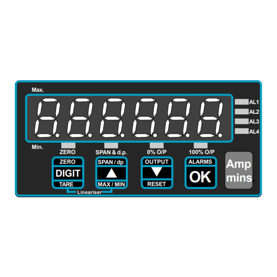
Max.
Min.
ZERO
ZERO
DIGIT
TARE
Ampere Time Display Meter
Plating Current monitor with pulsed outputs
Document Ref:pm65\manuals\INTUITIVE_AH
SPAN & d.p.
0% O/P
100% O/P
OUTPUT
ALARMS
SPAN / dp
OK
RESET
MAX / MIN
Lineariser
Model INT-AH
Rev AH 1.1 Software Version
IEC 1010
89/336/EEC
Revision:1 Dated: 31 July 2003
AL1
AL2
AL3
AL4
Amp
mins.
Advertisement
Table of Contents

Related Manuals for London Electronics INT-AH


Summary of Contents for London Electronics INT-AH
- Page 1 OUTPUT ALARMS SPAN / dp DIGIT mins. RESET TARE MAX / MIN Lineariser Ampere Time Display Meter Plating Current monitor with pulsed outputs Model INT-AH Rev AH 1.1 Software Version IEC 1010 89/336/EEC Document Ref:pm65\manuals\INTUITIVE_AH Revision:1 Dated: 31 July 2003...
- Page 2 Notes...
-
Page 3: Table Of Contents
Alphabetic Index Alarm board Configuration Alarms, how to set Calibration Calibration Examples Calibration - Tamper detection Connections Decimal point position selection Declaration of Conformity Failsafe alarm setting General description Getting Started Installing options Introduction Input connection examples Reset command Revisions record Specifications Warnings... -
Page 4: Introduction
Important Introductory Notes Please feel welcome to contact us if you need help, have a complaint, or if you have suggestions for improving our products or services. If you contact us about a product you already have, please give us as much information as you can, so we can give you accurate and swift help. - Page 5 Warnings Please carefully read all warnings and ONLY install the meter when you are sure that you’ve covered all aspects. * Connect the meter according to current IEE regulations and separate all wiring according to IEC1010. * Power supplies to this equipment must be anti-surge fused at 125mA for 230V supply, 250mA for 110V supply or 1A for DC supplies in the range 11-30VDC.
-
Page 6: General Description
General Description This meter has been designed to be simple to configure. It is easy to use because no menu is used. Look at the front panel below... to adjust ZERO you press the ZERO button, to adjust Span you press the SPAN button, to adjust Alarms you press the ALARM button. -
Page 7: Getting Started
Getting Started First, please check that the display will suit all the requirements of your application. Page 4 has some important warnings - please check that all warnings are covered. If you have alarm relay output options, you may need to configure the board before installing the meter in a panel. -
Page 8: Connections
Connections These connectors are only used when options are fitted OPTIONAL ALARM RELAY OUTPUTS AL2 and AL4 are pulsed outputs 14 15 16 17 18 19 20 21 22 23 24 25 26 27 REAR VIEW 1 2 3 4 5 6 7 8 9 10 11 12 13 Mains Power model DC Power model... -
Page 9: Calibration
Calibration Set switch 1, near the input connector ON and lockout switch OFF 1) How to set SPAN and DECIMAL POINT Press the SPAN button for 3 seconds. You will see ‘Int H’ or ‘Int M’ to allow you to calibrate in counts per hour or minute. -
Page 10: Calibration Examples
Calibration Examples You have a 75mV shunt rated at 200 Amperes and want to display ampere hours to a resolution of 0.1Ah a. Set ‘Int H’ because you want to count ampere HOURS b. Set InHi = 75.00 mV c. Set rd Hi to 200.0 d. -
Page 11: Calibration - Tamper Detection
Features Calibration Counter / Tamper detector An internal totaliser counts each calibration. To see the cal count, press the left- hand button at power-on. The ‘CAL XX’ value appears for a second or two after you switch the meter on. The number starts at 00 and can go up to FF (255 counts). -
Page 12: Installing Options
How to install alarm option boards If you want to open the meter to install or modify option boards, follow these steps... 1) Switch off power to the meter and unplug all connectors. 2) Unclip the front bezel. This is easier if you squeeze the top and bottom of the case, near the front. -
Page 13: Alarm Board Configuration
Alarm Board Configuration & Adjustment For failsafe operation (where contacts open on alarm or when power is lost to the meter) set the jumpers for OPEN CONTACTS and DE-ENERGISE on alarm. To access to the alarm board, first remove power from meter, including any power which might be on the alarm output circuitry. -
Page 14: Alarms, How To Set
Alarm settings NOTE : totalisation stops during alarm adjustment Alarm 1 and 3 relate to the accumulated total. Alarm 2 and 4 relate to pulsed outputs. If you press the ALARMS button momentarily, you can view each of the 4 alarm settings (each press will illuminate in turn AL1, AL2, AL3 and AL4 LEDs). -
Page 15: Specifications
Equipment Specifications Bezel size 48mm high by 96 mm wide (1/8 DIN) Panel Cutout 45 mm high by 92 mm wide Case Depth 125 mm including connectors Weight 300 grammes Case Material Black polycarbonate Connectors Detachable Screw Terminal connectors Power 95-265 VAC or 11-30 VDC optional Burden 8VA maximum... -
Page 16: Revisions Record
Record of Revisions/Changes .31 July 2003 Released Page 13... - Page 17 Notes Page 14...
- Page 18 Max. 48.0 Min. ZERO SPAN & d.p. 0% O/P 100% O/P ZERO SPAN / dp OUTPUT ALARMS DIGIT RESET TARE MAX / MIN Lineariser 96.0 92.0 Page 15...
- Page 19 12.0 102.0 22.0 92.0 Page 16...
-
Page 20: Declaration Of Conformity
Declaration of Conformity Declaration Reference : INTUITIVE Issue Date : 9 October 1998 revised 31 July 2003 Products Covered : INTUITIVE series Title : DOC-INTUITIVE This is to confirm that the Product covered by this declaration have been designed and manufactured to meet the limits of the following EMC Standard : EN61326-1:1997 and has been designed to meet the applicable sections of the following safety standards...
Need help?
Do you have a question about the INT-AH and is the answer not in the manual?
Questions and answers