Table of Contents
Advertisement
Quick Links
London Electronics Limited
Thorncote Road, Near Sandy, Bedfordshire SG19 1PU
Tel +44(0)1767 626444
www.london-electronics.com help@london-electronics.com
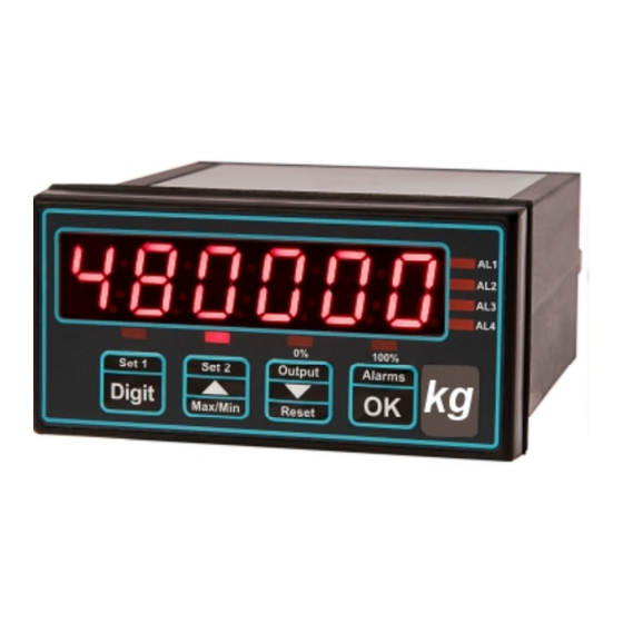
Panel mounting process meter
Model INT4-P
Installation & Operating Manual
Easy setup
Accepts 4-20mA, 0-10V, potentiometer
Display = 3, 4, 5 or 6 digits (configurable)
Optional Output 4-20mA / 0-10V isolated
Optional Alarm output = 2 or 4 relays
Optional Comms Output = RS232 or RS485
110-230V AC or 11-30V DC power
Caution: There is a risk of electrical
shock if this instrument is not properly installed
Caution: Risk of danger: Read the whole
manual before you install this meter
Software version F04.01
Fax +44(0)1767 626446
Revision:3
Dated: 13 March 2019
!
1
Advertisement
Table of Contents

Subscribe to Our Youtube Channel
Related Manuals for London Electronics INTUITIVE INT4-P


Summary of Contents for London Electronics INTUITIVE INT4-P
- Page 1 London Electronics Limited Thorncote Road, Near Sandy, Bedfordshire SG19 1PU Tel +44(0)1767 626444 Fax +44(0)1767 626446 www.london-electronics.com help@london-electronics.com Panel mounting process meter Model INT4-P Installation & Operating Manual Easy setup Accepts 4-20mA, 0-10V, potentiometer Display = 3, 4, 5 or 6 digits (configurable)
-
Page 2: Warranty
Warranty We warrant this product against defects in materials or workmanship for a period of three (3) years from the date of purchase. In the event of a defect during the warranty period, the unit should be returned, freight (and all duties and taxes) prepaid by the Buyer to the authorised distributor from where the unit was purchased. -
Page 3: Table Of Contents
Contents Warranty Warnings Introduction General Description Panel mounting & Installation - Class II DIN Rail mounting option Other Mounting options Wiring Advice Connections Installation hints for best performance 12-13 Application Notes Language Selection Display Brightness Display Calibration Modes Direct Calibration 18-19 Linearisation with Direct Calibration 20-21... -
Page 4: Warnings
Warnings Please carefully read this manual and all warnings. Install the meter ONLY when you are sure that you’ve covered all aspects. Where the product is intended for “UL” installations, removal or addition of option boards is not permitted. Check that the model number and supply voltage suit your application before you install the meter. -
Page 5: Introduction
Introduction Please contact us if you need help, if you have a complaint, or if you have suggestions to help us improve our products or services. If you contact us about a product you already have, please tell us the full model number and serial number, so that we can give you accurate and fast help. -
Page 6: General Description
General Description This series of meters accepts industrial sensors to allow various physical measurements to be made, such a weight, temperature, pressure, humidity etc. Different models are available for different sensor types. The main function of this series is to give a numeric readout of the variable being monitored. Most models include an excitation power output, to power the sensor directly. -
Page 7: Panel Mounting & Installation - Class
Panel Mounting and Installation - Class II Install the meters in a suitable protective electrical control enclosure according to local wiring regulations. See specifications for maximum allowable temperature in enclosure. Allow adequate air circulation. Installing into front of panel 92mm +1mm -0mm Slide the meter, with gasket into the panel cutout Remove the two rear bracket... -
Page 8: Din Rail Mounting Option
DIN Rail Mounting option This Series is ideal if you need high precision signal conditioning. Sometimes, it is not necessary to have front panel indication, so in such cases, we offer a DIN rail mounting option, which allows the meter to be installed within a control panel. Detachable connectors add to the simplicity of installation, and of course the setup method is identical to the panel mounting version, so you don’t need to learn a new method. -
Page 9: Other Mounting Options
Other mounting options IP67 SPC4 The SPC4 splashproof cover gives IP67 / NEMA4-X protection for the front of your meter. Ideal for use in harsh wet environments. Available with optional security tag ports to allow you to fit your own crimped wire tamper-seals, to pre- vent or indicate unauthorised access (Similar to tags used on electricity... -
Page 10: Wiring Advice
Wiring Advice This meter uses detachable screw terminal connectors. Refer to the wiring diagram on the following page for the correct positioning of each wire. The conductors you use must be suitable for the meter’s temperature, current and voltage rating, which is broadly described as follows:- Cable Temperature Rating All cables must be rated for operation up to 90C continuous. -
Page 11: Connections
Connections R S 2 3 2 Enable is used in mode C1 to activate or de-activate the RS232 or RS485 serial output. Connect to Comm to continually Connectors and options transmit data. Connectors may be present R S 4 8 5 even if output options are not installed. -
Page 12: Installation Hints For Best Performance
Installation hints for best performance This section offers several suggestions which will help you get the best performance from your measurement system. Some sensors generate comparitively small signals which can easily be corrupted by the potentially high level of electrical noise which can be created by electrical machinery such as motors, welding systems, discharge lighting, AC power inverters and solenoids. -
Page 14: Application Notes
Application Notes... -
Page 15: Language Selection
Language Selection for user interface You can select English or French menu prompts. Set2 Output Set1 Alarms Lockout Switch must be OFF Digit Max/Min Reset Circuit board Press together, briefly Display shows Set2 Output Set1 Alarms Digit Max/Min Reset UI Eng (Default) for User Interface English Press to toggle... -
Page 16: Display Brightness
Display Brightness You can adjust the display brightness at any time, provided the display is locked. Set1 Set2 Output Alarms Digit Lockout Switch must be ON Max/Min Reset Circuit board Press 3 seconds Set1 Set2 Output Alarms Display shows bright Digit Max/Min Reset... -
Page 17: Display Calibration Modes
Meter Calibration Modes You can choose from two main calibration methods. 1. Direct Calibration - this is when you connect the meter to your system and make the meter read what you want it to, at 2 different points. This is the preferred calibration method, because it allows you to calibrate the system as a whole. -
Page 18: Direct Calibration
Direct Calibration - Full Scale Setting This is when you connect the meter to your system and make the meter read what you want it to, at 2 different points. This is the preferred calibration method, because it allows you to calibrate the system as a whole. How to do direct calibration:- If you have not done so before, please select Direct Calibration mode from the previous page. - Page 19 Direct Calibration - Zero Setting How to calibrate the ZERO point. Set1 Set2 Output Alarms Lockout Switch must be OFF Digit Max/Min Reset Circuit board Press 3 seconds Apply the lowest calibration signal Set2 Output Set1 Alarms you can achieve, ideally 0% of Digit Max/Min Reset...
-
Page 20: Linearisation With Direct Calibration
Linearisation with Direct Calibration If your system is non linear, you can calibrate the meter and correct for this with the lineariser function. You will need to apply a series of known loads, starting at 0 and working up to full scale. You will then tell the meter what it should read for each applied load. - Page 21 Linearisation with Direct Calibration - cont’d. Set2 Output Set1 Alarms The display will show SEt 01 and will Digit then show the actual mV signal from the Max/Min Reset loadcells. Apply your 1st known load to the system and press OK. The display will now show rd 01 You can now tell the meter what it should...
- Page 22 Theoretical Cal. - Decimal Point & Full Scale This is when you type in the sensor’s theoretical signal level at the top and bottom of its range and the value to display, for each signal level. If you have not done so before, please select Theoretical Calibration mode from the Meter Calibration page AND choose whether your input is current or voltage.
-
Page 23: Theoretical Calibration
Theoretical Calibration - Low end calibration This is when you type in the sensor’s theoretical signal level at the top and bottom of its range and the value to display, for each signal level. If you have not done so before, please select Theoretical Calibration mode from the Meter Calibration page. -
Page 24: Linearisation With Theoretical Calibration
Linearisation with Theoretical Cal. If your system is non linear, you can calibrate the meter and correct for this with the lineariser function. With this method, you can enter theoretical values for input signal and display values, with- out having to connect a sensor. First, you must select Theoretical Calibration Mode (see page on calibration Modes) Then, proceed as shown below... - Page 25 Linearisation with Theoretical Cal. - cont’d. Set1 Set2 Output Alarms The display will show In 01 followed by Digit an editing screen. Here you can enter your Max/Min Reset next calibration input signal level using DIGIT button to select each digit in turn. Increase or decrease the value of each digit using the UP or DOWN buttons.
-
Page 26: Sensor Drift Correction
Sensor Drift correction If your system is normally reading 0, for example as is typical with platform scales or a torque meter, you may find a small amount of sensor drift caused by changes in temperature, ageing etc. We can automatically correct for slow, long term drift, by comparing your signal to 0 every 30 seconds, and re-calibrating to remove any detected movement. -
Page 27: Logic Input Functions
Logic input functions The three contact closure inputs on the rear of the meter have default functions which are:- Contact closure 1 = Tare Contact closure 2 = Peak/Valley display Contact closure 3 = Reset You can re-assign these to include :HOLD, Nett/Gross value display, Memory page address 1,2 or 4 (only if Multi-memory MEM option is installed) Lockout Switch must be OFF Set2... -
Page 28: Logic Input Connections & Front Buttons
Logic input connections and front buttons The previous page explained how to select the functions of the 3 logic inputs. You can connect remote contact closures or open NPN collectors to activate these logic inputs. The logic input provides a 5V DC signal. When you connect this to common, a current of 1mA will flow. -
Page 29: Factory Defaults
Factory Defaults You can return the display to its factory default conditions whenever you wish. If you do so, you will permanently loose all your settings and will need to start from the beginning again. The calibration Audit Counter will NOT be reset, there is no way provided to reset this value, as it is intended as a secure record to indicate whether changes have been made to the display since it was last calibrated.. -
Page 30: Signal Filtering / Averaging
Signal Filtering / Averaging You can adjust the filtering time constant to reduce the effect of noise or instability on your input signal. A larger FIL value will give a more stable display, but the response to signal changes will be slower. - Page 31 Filter Jump value See the Easy/Advanced mode selection page near the beginning of this manual, and choose advanced mode. The Filter Jump value allows you to decide how the display will respond to a process step change. It does this by overriding the filtering, if the input signal moves by more than a chosen amount in one conversion.
-
Page 32: Last Digit Rounding
Last Digit rounding up by 1, 2, 5, 10, 20 or 50 You can adjust the way the display rounds up, which is useful if you want to display a very large number, but do not want jitter on the last digit. The display can be set to round up to the nearest 1 (no rounding) 2, 5, 10, 20 or 50 Set1 Set2... -
Page 33: Scale Factor Adjustment
Scale Factor adjustment After you have calibrated your meter, you can use the SCALE feature to make fine adjust- ments to calibration, without affecting the calibration itself, or you can convert to different units of measure. Examples 1.Changing weight units of measure from kg to pounds You can use the SCALE feature to convert your readout from kg to pounds, without affecting the calibration. -
Page 34: Offset Adjustment
Offset adjustment After you have calibrated your meter, you can use the OFFSET feature to make fine addi- tions or subtractions to the reading, without affecting the calibration itself. For example if your weighing structure is altered after calibration and you want to subtract the effect of 37kg of extra metalwork which was welded to the hopper, you can easily do this by entering a value of -37 in the offset value. -
Page 35: Menu Timeout Adjustment
Menu timeout adjustment The display has a default timeout of 60 seconds, to allow you sufficient time to refer to the manual between key operations. You can make this period shorter, if you wish, once you become more familiar with the setup method. -
Page 36: Reverse / Mirror Display Setting
Reverse Display function (mirror image) If you need to be able to see a reflection of the display in a mirror or other reflective surface, for example in a simple heads-up system, or for drivers reversing into a bay, using mirrors only, you can set the display to show as a mirror image. -
Page 37: Bootup Routine Choices
Bootup routine and Tare save choices When you switch on your meter, it can be set to power up with 3 possible summary mes- sage combinations. The choices are:- boot 0 Segment test, followed by a full summary of software revision, calibration audit number, model number, installed options. -
Page 38: Multi Memory Mem Option
Multi-Program Memory option MEM You can call up between 1 to 7 additional meter setup memories (pages), using the three contact closure inputs on the rear of the meter, if the MEM option has been installed. This allows you to save up to 8 complete sets of independent calibrations, alarm settings, ana- logue output settings and serial comms settings. -
Page 39: Error Codes
Error codes and fault finding 1. Under Range. The meter is being asked to display a value which is more --Ur-- negative than its limit of -199999 2. Over Range. The meter is being asked to display a value which is higher --Or-- than its limit of 999999 These fault codes could be displayed because the signal is too negative, too... -
Page 40: Output Options - Installing
How to install option boards Warning: Disconnect Where the product is intended for “UL” installations power before you expose removal or addition of option boards is not permitted. the rear of the meter If you want to open your meter to install or modify option boards, follow these steps... Switch off power to the meter and unplug all connectors. -
Page 41: Weee
Waste Electrical Electronic Equipment (WEEE) In Europe, this equipment must be disposed of in accordance with European Parliamentary Directive 2002/96/EC This directive encourages recycling and the reduction of waste materials in the environment. This means it must be sent to an approved recycling plant if you want to dispose of it. It must not be thrown away with general rubbish. -
Page 42: Equipment Specifications
Equipment Specifications Bezel size 48mm high by 96 mm wide (1/8 DIN) Panel Cutout 45 mm high by 92 mm wide Case Depth 125 mm including connectors Weight 300 grammes Case Material Black polycarbonate Connectors Detachable Screw Terminal connectors Environmental Storage Temperature range -20 to +70C, non condensing Operating temperature range 0 to 50C, non condensing Front sealed IP65. -
Page 43: Declaration Of Conformity
All signal cabling shall be screened. The screen shall only be terminated to the power earth terminal at the meter end of the cable. Declared as true and correct, for and on behalf of London Electronics Ltd. J.R.Lees Director... - Page 44 We design and manufacture a wide range of standard and custom monitoring and control equipment. All our UK manufactured products have a 3 year warranty. Real-Time Production-Line Displays Large Digital Displays sealed IP65 Digital Panel Meters Power Monitors Bargraph Displays Message Displays sealed IP65 Signal Transmitters / Isolators...
Need help?
Do you have a question about the INTUITIVE INT4-P and is the answer not in the manual?
Questions and answers