
Subscribe to Our Youtube Channel
Related Manuals for London Electronics INT5


Summary of Contents for London Electronics INT5
- Page 1 UNIVERSAL INPUT DIGITAL PANEL METER USER MANUAL F0.03 b.070 Publication date 26-01-2024 Revision 2 www.london-electronics.com...
-
Page 2: Table Of Contents
INT5 User Manual Table of Contents 1. Introduction......................6 1.1. Features ........................... 1 1.2. Standard Input Signals ......................1 1.3. Optional Input Signals ......................2 1.4. Optional Output Signals ......................2 1.5. Ordering Codes ........................3 1.6. Indicator LED’s ........................4 1.7. - Page 3 INT5 User Manual Table of Contents 4.11. Factory Defaults ........................34 5. Display / Reading Adjustment................35 5.1. Stabilisation ........................... 36 5.2. Automatic Drift Cancelling ....................37 5.3. Linearisation .......................... 39 5.3.1. Preparing your Data .......................40 5.3.2. Activate the Lineariser ....................41 5.4.
- Page 4 INT5 User Manual Table of Contents 6.11. Thermocouple Input Mode....................104 6.11.1. Connections........................105 6.11.2. Thermocouple Types ....................106 6.11.3. How to Calibrate Your Meter..................107 6.11.4. External Fixed Cold Junction ..................109 6.12. Elapsed Timer Mode (Up and Down Timing) ..............110 6.12.1. Connections ....................... 111 6.12.2.
- Page 5 INT5 User Manual Table of Contents 8.9.1. Set.H and Set.L ......................151 8.9.2. Set.P..........................152 8.10. Hysteresis .......................... 153 8.11. On Time Delay........................154 8.12. Timed Pulse Output Duration................... 155 8.13. Off Time Delay ........................156 8.14. Installation Hints for Best Performance ................157 9.
-
Page 6: Introduction
The INT5 is the fifth generation of our popular 1/8 DIN INTUITIVE panel meter range. Its’ unique universal sensor input, puts this meter in a class of its own. The 32-bit A/D converter makes the INT5 the fastest, highest performing, panel meter we have produced to date and our patented multi-sensor design makes it the most universal meter ever. -
Page 7: Features
INT5 User Manual 1.1. Features Two power supply options: 95-265V AC / 100-300V DC or 11-30V DC Programmed using front panel push buttons Ingress protection to IP65 from the front, IP67 optional Multi-sensor / multi-function capability 6 digits, LED, 3 colours... -
Page 8: Optional Input Signals
INT5 User Manual 1.3. Optional Input Signals Power Frequency measurement 47.000 to 63.000 Hz Real Time clock, calendar, day counter 1.4. Optional Output Signals 4-20mA isolated, scalable, active source passive sink 0-10V isolated, scalable x4 SPDT mechanical relays RS232 RS485 + Modbus ASCII + Modbus RTU Page 2 www.london-electronics.com... -
Page 9: Ordering Codes
INT5 User Manual 1.5. Ordering Codes INT5 -X -X -X -X -X -X -X -X Function / Input Type: Digital input (counter, rate meter, elapsed timer) Power frequency monitor (AC powered only) Real time clock Universal input (analogue and digital signals) -
Page 10: Indicator Led's
INT5 User Manual 1.6. Indicator LED’s Your display has indicator LED's which give status information during set-up and operation. Cal Lo Cal Hi An Out Alarms DIGIT Tare Pk/Val Reset Alarm Indicators In normal operation, these LED's will be unlit. -
Page 11: Front Panel Buttons
INT5 User Manual 1.7. Front Panel Buttons Each button has several functions. They are normally locked when the meter is being used, to prevent unwanted changes to the configuration. Cal Lo Cal Hi An Out Alarms DIGIT Tare Pk/Val Reset Page 5 www.london-electronics.com... -
Page 12: Inventory Report
INT5 User Manual 1.8. Inventory Report You do not need to unlock the meter to view the inventory report. The Inventory report shows the meter's hardware and software status. It includes input mode, board temperature, firmware version, firmware build number and installed option boards. -
Page 13: Safety
INT5 User Manual Safety Page 7 www.london-electronics.com... - Page 14 INT5 User Manual Please carefully read this manual and all warnings. Install the meter ONLY when you are sure that you’ve covered all aspects. Check that the model number and supply voltage suit your application before you install the meter.
-
Page 15: Installation
INT5 User Manual Installation Page 9 www.london-electronics.com... -
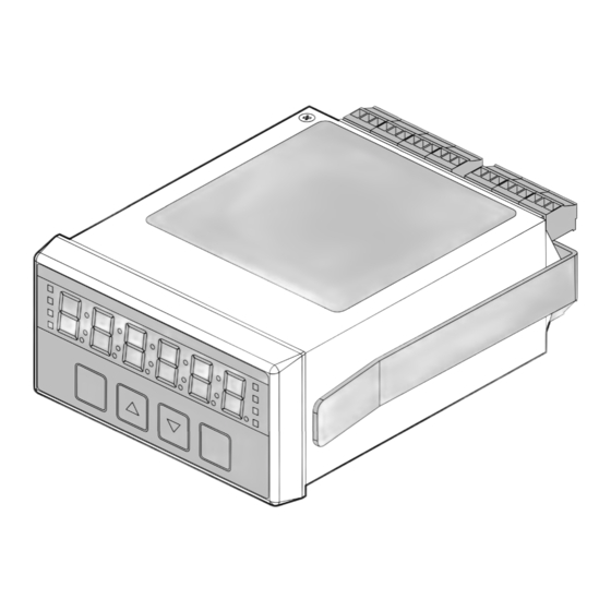
Page 16: External Parts
INT5 User Manual 3.1. External Parts Overlay Information Label Connectors Front Panel Panel Mounting Bracket Page 10 www.london-electronics.com... -
Page 17: Connectors
INT5 User Manual 3.2. Connectors The pin out for the connectors will vary depending on the settings you have configured 1920 21222324 252627 282930 313233 343536 373839 16 17 18 3 4 5 6 7 8 9 10 11 12 13 14 15... -
Page 18: Panel Mounting
INT5 User Manual 3.3. Panel Mounting Gasket Panel Bracket Page 12 www.london-electronics.com... -
Page 19: Optional Din Rail Mounting
INT5 User Manual 3.4. Optional DIN Rail Mounting The equipment must be electrically grounded through the DIN rail for EMC compliance. Make sure that the equipment is correctly mounted on the rail and that the rail is properly grounded. Page 13... -
Page 20: Connecting To Power
INT5 User Manual 3.5. Connecting to Power Caution Ensure that the power supply is turned off before connecting it to the equipment. Using the wrong type of power voltage will damage the equipment. Ensure that the power voltage is connected properly and of the recommended type. See the rating label on the meter for its power voltage. -
Page 21: Functionality
INT5 User Manual Functionality Page 15 www.london-electronics.com... -
Page 22: Locking And Editing Settings
INT5 User Manual 4.1. Locking and Editing Settings Caution When you switch your meter on, it will be locked automatically. Before you can change your configuration settings you must first unlock the configuration menu. There are 2 Unlocked 'edit' modes. -
Page 23: Brightness Adjustment
INT5 User Manual 4.2. Brightness Adjustment The display has 10 levels of brightness. You can change the brightness at any time during normal operation, when the meter is locked. Press button 2 for at least 3 seconds. The display will say 'bri.X'... -
Page 24: Display Colour
INT5 User Manual 4.3. Display Colour You can set the normal display colour to be Red, Yellow or Green. Unlock the configuration menu Press and hold buttons 3 and 4 together for at least 3 seconds. The display will say either: Press button 2 (△) or 3 (▽) to set the colour you want. -
Page 25: Main Display Value
INT5 User Manual 4.4. Main Display Value You can set the display to permanently show one of several different sources of data. For example, you can configure the display to permanently show the peak, or valley, or the nett value, or the gross value, or the tare value, etc. - Page 26 INT5 User Manual The Valley Nett Value This shows the lowest Nett value since the valley was last reset. The Tare Value This shows the tare amount. For example, in a weighing application, your platform has nothing on it and reads 0 You place an empty container weighing 78kg on the platform and the display reads 78.
-
Page 27: Setting The Main Display Value
INT5 User Manual 4.4.1. Setting the Main Display Value Unlock the configuration menu Press Buttons 3 and 4 together for 3 seconds. The 'dISP' prompt will appear. You can use button 2 (△) or 3 (▽) to set one of the listed permanent display values. -
Page 28: Logic Inputs
INT5 User Manual 4.5. Logic Inputs Caution Ensure that the power supply is turned off before connecting it to the equipment. Using the wrong type of input signal can damage the equipment. Ensure that the input signal is connected properly and of the recommended type. -
Page 29: Connections
INT5 User Manual 4.5.2. Connections N.O. N.C. Signal Input Description Contact closure #1 9 10 11 1314 15 Contact closure #2 Contact closure #3 Contact closure #4 Contact closure #5 Contact closure #6 * If your meter has the P.FrE power frequency function fitted, logic port #6 will not be available. -
Page 30: Contact Closure Input Port Function
INT5 User Manual 4.5.3. Contact Closure Input Port Function Legend Function Description Default Clear counts, Tare, Timer, latched alarms, Reset Peak/valley memory etc. Clear the display value to 0, regardless of Tare weight acting upon load cell Hold Freeze the meter state at a moment in time... -
Page 31: How To Configure Your External Contact Closure Input Functions
INT5 User Manual 4.5.4. How to configure your external contact closure input functions Unlock the configuration menu Press buttons 3 and 4 together for 3 seconds. The meter will show 'diSP' Then it will show the existing display parameter. Press button 4 repeatedly until you see 'E.CC.n' Press the 2(△) or 3(▽) button until you see 'E.CC.Y'... - Page 32 INT5 User Manual To choose the function of that channel press button 2(△) or 3(▽) until you see your desired function. To save that function, press button 4 (OK) Choose a debounce time for that channel. The default is 50 mS.
-
Page 33: Boot-Up Modes
INT5 User Manual 4.6. Boot-up Modes You can choose what happens on the display when you first switch on the meter. There are 5 power-on or boot-up modes available: bt. 0 Meter immediately displays measurement data. bt. 1 Meter does a display test, then displays measurement data. -
Page 34: Active Digits
INT5 User Manual 4.7. Active Digits You can choose to have 4 or 6 digits active on this display. Unlock the configuration menu Press Buttons 3 and 4 together for 3 seconds. The 'dISP' prompt will appear. Press button 4 (OK) until you see 'diG.6' or 'diG.4'. -
Page 35: Front Button Functions
INT5 User Manual 4.8. Front Button Functions Each button has several functions. They are normally locked when the meter is being used, to prevent unwanted changes to the configuration. 4.8.1. Front Button Tare Button 1 can be enabled as a tare or zero button. -
Page 36: Front Button Peak And Valley
INT5 User Manual 4.8.2. Front Button Peak and Valley Button 2 can be used to see the peak or valley when in an operating mode that would require a peak or valley reading, for example, Load Cell. Press briefly and repeatedly on button 2 (△) to see Peak (maximum memory, PV LED is Yellow) and Valley (minimum memory, PV LED is Green) stored values and the live value. -
Page 37: Front Button Reset
INT5 User Manual 4.8.3. Front Button Reset Button 3 can be enabled as a reset button. Unlock the configuration menu Press buttons 3 and 4 together for 3 seconds. The meter will show 'diSP' Then it will show the existing display parameter. -
Page 38: Power Frequency
INT5 User Manual 4.9. Power Frequency If your model number includes 'PFM' and the meter is AC powered, you can display precise power frequency. Frequency is displayed to 3 decimal places. Range 47.000 to 63.000 Hz. 95-265V AC. The meter measures the frequency of its own power voltage, no auxiliary connection is needed. -
Page 39: Ambient Temperature Sensor
INT5 User Manual 4.10. Ambient Temperature Sensor There is a temperature sensor on the rear of the meter, between the analogue input terminals and the contact closure input terminals. It gives cold junction compensation for thermocouple measurements, but can also show the meter's ambient temperature when in another measurement mode. -
Page 40: Factory Defaults
INT5 User Manual 4.11. Factory Defaults You can return the display to its factory default conditions whenever you wish. If you do so, you will permanently loose all your settings and will need to start from the beginning again. Unlock the configuration menu Press and hold buttons 1, 2, 3 and 4 together for at least 3 seconds until the display shows 'dEF.n'... -
Page 41: Display / Reading Adjustment
INT5 User Manual Adjustments Page 35 www.london-electronics.com... -
Page 42: Stabilisation
INT5 User Manual 5.1. Stabilisation This function helps you to stabilise a reading which is moving because of input signal fluctuations. The more stabilisation you add, the slower will be the display's response, so some compromise is required between stability and speed. -
Page 43: Automatic Drift Cancelling
INT5 User Manual 5.2. Automatic Drift Cancelling Drift cancelling is useful if your display reads 0 most of the time. This is common in weighing applications, destructive test force applications etc. Temperature changes can cause drift in the sensor and display. - Page 44 INT5 User Manual To define how often you will check for drift, in seconds, edit 'drF.t' Press button 1 (Digit) to select each digit and edit with button 2 (△) or 3 (▽) to define how often you will check for drift, in seconds.
-
Page 45: Linearisation
INT5 User Manual 5.3. Linearisation After basic direct or theoretical calibration, you can easily linearise your system if its errors are repeatable. The lineariser is easy to use. You can switch it on or off at any time, so you can compare linearised and non-linearised responses. -
Page 46: Preparing Your Data
INT5 User Manual 5.3.1. Preparing your Data Before you enter any values, record what the display shows, without linearising, at several points and what you want it to show. For example, in a weighing system, the engineer checked various readings with test weights and wrote down these results... -
Page 47: Activate The Lineariser
INT5 User Manual 5.3.2. Activate the Lineariser Unlock the configuration menu Press and hold buttons 2 and 3 together for at least 3 seconds until the display shows 'Lin.0' or 'Lin.1' 'Lin.0' = The lineariser is turned off 'Lin.1' = The lineariser is turned on Press button 2 (△) or 3 (▽) to select 'Lin.1'... - Page 48 INT5 User Manual Press button 1 (Digit) to select each digit and edit with button 2 (△) or 3 (▽) to change the value. Press button 4 (OK) to proceed. The display will now briefly say 'rd.XX' to confirm you are editing in the Reading setting.
-
Page 49: Last Digit Tolerance
INT5 User Manual 5.4. Last Digit Tolerance In some applications, you may prefer your digital display to resolve to the nearest 2, 5, 10, 20 or 50 counts. For example, on a weigh bridge, showing 0-10000 kg, you may wish to display to the nearest 10 kg. -
Page 50: Offset Adjustment
INT5 User Manual 5.5. Offset Adjustment After you have calibrated your meter, you can use the 'OF.St' feature to make fine additions or subtractions to the reading, without affecting the calibration itself. For example if your weighing structure is altered after calibration and you want to subtract the effect of 37kg of extra metalwork which was welded to the hopper, you can easily do this by entering a value of -37 in the offset value. -
Page 51: Scale Factor Adjustment
INT5 User Manual 5.6. Scale Factor Adjustment After you have calibrated your meter, you can use the 'SCAL' feature to make fine adjustments to calibration, without affecting the calibration itself, or you can convert to different units of measure. Examples:... - Page 52 INT5 User Manual To save your choice, press button 4 (OK) Press button 1 (Digit) to select each digit and edit with buttons 2 (△) or 3 (▽) to increase or decrease the scale value. To set decimal point position, press button 2 (Cal Hi) again for 3 seconds and move the decimal point to the desired position with buttons 2(△) or 3(▽) .
-
Page 53: Signals
INT5 User Manual Signals Page 47 www.london-electronics.com... -
Page 54: How To Choose Your Input Type
INT5 User Manual 6.1. How to Choose Your Input Type Unlock the configuration menu Press buttons 1 (Digit) and 2 (△) together for at least 6 seconds. (ignore 'c.src') The display will say: 'tYPE' Press button 2 (△) or 3 (▽) repeatedly until you see... -
Page 55: 0-10V Input Mode
INT5 User Manual 6.2. 0-10V Input Mode Caution Ensure that the power supply is turned off before connecting it to the equipment. Using the wrong type of input signal can damage the equipment. Ensure that the input signal is connected properly and of the recommended type. -
Page 56: Connections
INT5 User Manual 6.2.1. Connections Signal Input Description 1 2 3 4 5 6 7 - V DC (must be linked to terminals 4 and 5) - V DC (must be linked to terminals 1 and 5) - V DC (must be linked to terminals 1 and 4) -
Page 57: How To Calibrate Your Meter
INT5 User Manual 6.2.2. How to calibrate your meter There are 2 calibration methods available: Direct Calibration Method Direct calibration is more accurate, because it calibrates the whole system, including the sensor. Unlock the configuration menu Connect your sensor to the meter and to your process. - Page 58 INT5 User Manual High Calibration Point Press button 2 (Cal Hi) for 3 seconds. The display will say 'dir' to confirm you are in Direct calibration mode, and will then say 'InHi'. Apply the high level calibration signal 9.000V in the example, and press button 4 (OK).
- Page 59 INT5 User Manual Low Calibration Point Press button 1 (Cal Lo) for 3 seconds. The display will say 'dir' to confirm you are in direct calibration mode, and will then say 'InLo'. Apply the low level calibration signal 1.000V in the example, and press button 4 (OK).
- Page 60 INT5 User Manual Theoretical Calibration Method Theoretical calibration allows you to define two input and corresponding display values, without needing to connect a sensor to the display. It is not as accurate as direct calibration, because we do not include the sensor in the calibration, but it is useful as an approximate calibration method.
- Page 61 INT5 User Manual High Calibration Point Press button 2 (Cal Hi) for 3 seconds. The display will say 'thEo' to confirm you are in theoretical calibration mode, and will then say 'InHi'. It will then show the existing 'InHi' value, which you can edit, as follows.
- Page 62 INT5 User Manual Press button 1 (Digit) repeatedly, to highlight individual digits. Press buttons 2 (△) or 3 (▽) to set 75.0 or your desired 'rdHi' reading. Press button 4 (OK) when all digits are correct. Page 56 www.london-electronics.com...
- Page 63 INT5 User Manual Low Calibration Point Press button 1 (Cal Lo) for 3 seconds. The display will say 'thEo' to confirm you are in theoretical calibration mode, and will then say 'InLo'. It will then show the existing 'InLo' value, which you can edit, as follows.
- Page 64 INT5 User Manual Press button 1 (Digit) repeatedly, to highlight individual digits. Press buttons 2 (△) or 3 (▽) buttons to set 0.0 or your desired 'rdLo' reading. Press button 4 (OK) when all digits are correct. The meter will lock itself automatically within 5 minutes, or immediately, if you switch the meter off then on again.
-
Page 65: 4-20Ma Input Mode
INT5 User Manual 6.3. 4-20mA Input Mode Caution Ensure that the power supply is turned off before connecting it to the equipment. Using the wrong type of input signal can damage the equipment. Ensure that the input signal is connected properly and of the recommended type. - Page 66 INT5 User Manual Active 4-20mA Signal Input Description 1 2 3 4 5 6 7 - mA (must be linked to terminals 4 and 5) + mA - mA (must be linked to terminals 1 and 5) - mA (must be linked to terminals 1 and 4) Suitable if the signal is coming from an active device sending 4-20mA out.
-
Page 67: How To Calibrate Your Meter
INT5 User Manual 6.3.2. How to calibrate your meter There are 2 calibration methods available: Direct Calibration Method Direct calibration is more accurate, because it calibrates the whole system, including the sensor. Unlock the configuration menu Connect your sensor to the meter and to your process. - Page 68 INT5 User Manual High Calibration Point Press button 2 (Cal Hi) for 3 seconds. The display will say 'dir' to confirm you are in direct calibration mode, and will then say 'InHi'. Apply the high level calibration signal 20.000mA in the example, and press button 4 (OK).
- Page 69 INT5 User Manual Low Calibration Point Press button 1 (Cal Lo) for 3 seconds. The display will say 'dir' to confirm you are in direct calibration made, and will then say 'InLo'. Apply the low level calibration signal 4.000mA in the example, and press button 4 (OK).
- Page 70 INT5 User Manual Theoretical Calibration Method Theoretical calibration allows you to define two input and corresponding display values, without needing to connect a sensor to the display. It is not as accurate as direct calibration, because we do not include the sensor in the calibration, but it is useful as an approximate calibration method.
- Page 71 INT5 User Manual High Calibration Point Press button 2 (Cal Hi) for 3 seconds. The display will say 'thEo' to confirm you are in theoretical calibration mode, and will then say 'InHi'. It will then show the existing 'InHi' value, which you can edit, as follows.
- Page 72 INT5 User Manual Press button 1 (Digit) repeatedly, to highlight individual digits. Press buttons 2 (△) or 3 (▽) buttons to set 75.0 or your desired 'rdHi' reading. Press button 4 (OK) when all digits are correct. Page 66 www.london-electronics.com...
- Page 73 INT5 User Manual Low Calibration Point Press button 1 (Cal Lo) for 3 seconds. The display will say 'thEo' to confirm you are in theoretical calibration mode, and will then say 'InLo'. It will then show the existing 'InLo' value, which you can edit, as follows.
- Page 74 INT5 User Manual Press button 1 (Digit) repeatedly, to highlight individual digits. Press buttons 2 (△) or 3 (▽) to set 0.0 or your desired 'rdLo' reading. Press button 4 (OK) when all digits are correct. The meter will lock itself automatically within 5 minutes, or immediately, if you switch the meter off then on again.
-
Page 75: Dc Shunt Input Mode
INT5 User Manual 6.4. DC Shunt Input Mode Caution Ensure that the power supply is turned off before connecting it to the equipment. Using the wrong type of input signal can damage the equipment. Ensure that the input signal is connected properly and of the recommended type. -
Page 76: Connections
INT5 User Manual 6.4.1. Connections Signal Input Description 1 2 3 4 5 6 7 - V (must be linked to terminals 4) - V (must be linked to terminals 1) + 50, 60, 75, 100mV Page 70 www.london-electronics.com... -
Page 77: How To Calibrate Your Meter
INT5 User Manual 6.4.2. How to Calibrate Your Meter There are 2 calibration methods available: Direct Calibration Method Direct calibration is more accurate, because it calibrates the whole system, including the shunt. Unlock the configuration menu Connect your shunt to the meter and to your process. - Page 78 INT5 User Manual High Calibration Point Press button 2 (Cal Hi) for 3 seconds. The display will say 'dir' to confirm you are in direct calibration mode, and will then say 'InHi'. Apply the high level calibration signal 250A in the example, and press button 4 (OK).
- Page 79 INT5 User Manual Low Calibration Point Press button 1 (Cal Lo) for 3 seconds. The display will say 'dir' to confirm you are in direct calibration made, and will then say 'InLo'. Apply the low level calibration signal 0A in the example, and press button 4 (OK).
- Page 80 INT5 User Manual Theoretical Calibration Method Theoretical calibration allows you to define two input and corresponding display values, without needing to connect a shunt to the display. It is not as accurate as direct calibration, because we do not include the shunt in the calibration, but it is useful as an approximate calibration method.
- Page 81 INT5 User Manual High Calibration Point Press button 2 (Cal Hi) for 3 seconds. The display will say 'thEo' to confirm you are in theoretical calibration mode, and will then say 'InHi'. It will then show the existing 'InHi' value, which you can edit, as follows.
- Page 82 INT5 User Manual Press button 1 (Digit) repeatedly, to highlight individual digits. Press buttons 2 (△) or 3 (▽) to set 400.0 or your desired 'rdHi' reading. Press button 4 (OK) when all digits are correct. Page 76 www.london-electronics.com...
- Page 83 INT5 User Manual Low Calibration Point Press button 1 (Cal Lo) for 3 seconds. The display will say 'thEo' to confirm you are in theoretical calibration mode, and will then say 'InLo'. It will then show the existing 'InLo' value, which you can edit, as follows.
- Page 84 INT5 User Manual Press button 1 (Digit) repeatedly, to highlight individual digits. Press buttons 2 (△) or 3 (▽) to set 0.0 or your desired 'rdLo' reading. Press button 4 (OK) when all digits are correct. The meter will lock itself automatically within 5 minutes, or immediately, if you switch the meter off then on again.
-
Page 85: Load / Weight Input Mode
INT5 User Manual 6.5. Load / Weight Input Mode Caution Ensure that the power supply is turned off before connecting it to the equipment. Using the wrong type of input signal can damage the equipment. Ensure that the input signal is connected properly and of the recommended type. -
Page 86: Connections
INT5 User Manual 6.5.1. Connections Signal Input Description 1 2 3 4 5 6 7 - Excitation - Signal + Signal + Excitation You can connect up to 4 x 350 Ohm or 8 x 700 Ohm load cells in parallel. -
Page 87: How To Calibrate Your Meter
INT5 User Manual 6.5.2. How to Calibrate Your Meter How to Choose a Calibration Method Direct calibration is recommended, because it calibrates the whole system including the display and the load cells and any leverage effects. You will put a known calibration weight on the platform and adjust the meter to read that weight exactly. - Page 88 INT5 User Manual Direct Calibration (Recommended) Choose direct calibration if you will put known calibration weights on the system to calibrate the display. We recommend this calibration mode, because it allows you to calibrate your whole weighing system in one procedure.
- Page 89 INT5 User Manual High Calibration Point Press button 2 (Cal Hi) for 3 seconds. The display will say 'dir' to confirm you are in direct calibration mode, and will then say 'InHi'. Apply the highest load value, ideally 100% of full load, and press button 4 (OK).
- Page 90 INT5 User Manual Theoretical Calibration To use theoretical calibration you will need to enter details from the load cell calibration certificate into the meter. The values you will need are: - Capacity - Sensitivity - Resistance - Number of load cells connected in parallel You do not need to connect the load cell to the meter for this calibration method.
-
Page 91: Potentiometer Input Mode
INT5 User Manual 6.6. Potentiometer Input Mode Caution Ensure that the power supply is turned off before connecting it to the equipment. Using the wrong type of input signal can damage the equipment. Ensure that the input signal is connected properly and of the recommended type. -
Page 92: Connections
INT5 User Manual 6.6.1. Connections Signal Input: 3 Wire Description 1 2 3 4 5 6 7 Signal Input: 4 Wire Description 1 2 3 4 5 6 7 Page 86 www.london-electronics.com... -
Page 93: Rtd / Pt100 Input Mode
INT5 User Manual 6.7. RTD / PT100 Input Mode Caution Ensure that the power supply is turned off before connecting it to the equipment. Using the wrong type of input signal can damage the equipment. Ensure that the input signal is connected properly and of the recommended type. -
Page 94: Connections
INT5 User Manual 6.7.1. Connections Signal Input: 2,3 and 4 Wire Description 1 2 3 4 5 6 7 Blue Green Yellow 1 2 3 4 5 6 7 1 2 3 4 5 6 7 Page 88 www.london-electronics.com... -
Page 95: How To Calibrate Your Meter
INT5 User Manual 6.7.2. How to calibrate your meter Unlock the configuration menu Press button 1 and 2 together for 3 seconds until you see 'C.Src' (calibration source) It will then ask you to set the resolution… '1°' deg resolution or '0.1°' deg resolution Press button 2 (△) or 3 (▽) until you see the resolution... -
Page 96: Rate/Rpm Input Mode
INT5 User Manual 6.8. Rate/RPM Input Mode Caution Ensure that the power supply is turned off before connecting it to the equipment. Using the wrong type of input signal can damage the equipment. Ensure that the input signal is connected properly and of the recommended type. -
Page 97: Connections
INT5 User Manual 6.8.1. Connections Signal Input Description +24V 9 10 11 1314 15 Pulse Signal Types NPN Transistors Switching 5V DC at 1mA Must saturate to lower than 1V Vce Normally Open / Closed Contacts Switching 5V DC at 1mA We recommend you use wiping contacts, to mechanically clear any oxidation or tarnishing of the contact surfaces. -
Page 98: Bin Concept
INT5 User Manual 6.8.2. Bin Concept Our rate measuring system uses the concept of 'bins', which is very user-friendly and flexible. A bin can be filled with the number of counted pulses it receives. You can set the time during which a bin is open. -
Page 99: How To Calibrate Your Meter
INT5 User Manual 6.8.3. How to Calibrate Your Meter Unlock the configuration menu Press button 1 and 2 together for 3 seconds until you see 'C.Src' (calibration source) The display will now briefly say 'P.in' prompting you to enter a maximum frequency in hertz, which will correspond to a desired display value. - Page 100 INT5 User Manual To set decimal point position, press button 2 (Cal Hi) again for 3 seconds and move the decimal point to the desired position with buttons 2(△) or 3(▽). Press button 4 (OK) to save. 'bn.00' will appear, prompting you to enter how many bins do you want to average.
- Page 101 INT5 User Manual Press button 1 (Digit) to select each digit and edit with buttons 2 (△) or 3 (▽). To set decimal point position, press button 2 (Cal Hi) again for 3 seconds and move the decimal point to the desired position with buttons 2(△) or 3(▽) .
-
Page 102: Total Input Mode
INT5 User Manual 6.9. Total Input Mode Caution Ensure that the power supply is turned off before connecting it to the equipment. Using the wrong type of input signal can damage the equipment. Ensure that the input signal is connected properly and of the recommended type. -
Page 103: Connections
INT5 User Manual 6.9.1. Connections Signal Input Description +24V 9 10 11 1314 15 Pulse Page 97 www.london-electronics.com... -
Page 104: How To Calibrate Your Meter
INT5 User Manual 6.9.2. How to Calibrate Your Meter Unlock the configuration menu Press button 1 and 2 together for 3 seconds until you see 'C.Src' (calibration source) The display will now briefly say 'P.in' prompting you to enter the number of input pulses. - Page 105 INT5 User Manual The display will now briefly say 'dbnc' prompting you to set a contact debounce filter time in milliseconds. Press button 1 (Digit) to select each digit and edit with buttons 2 (△) or 3 (▽) to show your desired frequency.
-
Page 106: Resistance Input Mode
INT5 User Manual 6.10. Resistance Input Mode Caution Ensure that the power supply is turned off before connecting it to the equipment. Using the wrong type of input signal can damage the equipment. Ensure that the input signal is connected properly and of the recommended type. -
Page 107: Connections
INT5 User Manual 6.10.1. Connections Signal Input Description 1 2 3 4 5 6 7 - Excitation - Signal + Signal + Excitation Page 101 www.london-electronics.com... -
Page 108: How To Calibrate Your Meter
INT5 User Manual 6.10.2. How to Calibrate Your Meter Unlock the configuration menu Press button 1 and 2 together for 3 seconds until you see 'C.Src' (calibration source) The display will now briefly say 'r.top' prompting you to set the maximum resistance value you want to measure. -
Page 109: How To Choose The Correct Resistance Range
INT5 User Manual 6.10.3. How to Choose the Correct Resistance Range Low Ranges Range Screen Prompt Excitation Current 1 Ohm maximum 50mA 10 Ohm maximum 100 Ohm maximum 0.5mA High Ranges Range Screen Prompt Excitation Current 1 kilOhm maximum 50uA... -
Page 110: Thermocouple Input Mode
INT5 User Manual 6.11. Thermocouple Input Mode Caution Ensure that the power supply is turned off before connecting it to the equipment. Using the wrong type of input signal can damage the equipment. Ensure that the input signal is connected properly and of the recommended type. -
Page 111: Connections
INT5 User Manual 6.11.1. Connections Signal Input Description 1 2 3 4 5 6 7 Example showing Thermocouple type T selection. Page 105 www.london-electronics.com... -
Page 112: Thermocouple Types
INT5 User Manual 6.11.2. Thermocouple Types You can choose from these thermocouple types: International Colour Code to IEC 60584-3 Screen Prompt Name Thermocouple Intrinsically Safe Thermocouple Cable Colour Colour Connector Colour Type B Type E Type J Type K Type N... -
Page 113: How To Calibrate Your Meter
INT5 User Manual 6.11.3. How to Calibrate Your Meter Unlock the configuration menu Press button 1 and 2 together for 3 seconds until you see 'C.Src' (calibration source) The display will ask you to set the resolution. Press buttons 2 (△) or 3 (▽) to change the menu to show your desired resolution, '1°' or '0.1°'. - Page 114 INT5 User Manual Cold Junction Compensation The display will now ask you to choose the cold junction compensation you want. In most applications you would choose 'Auto' To set a fixed cold junction temperature press buttons 2 (△) or 3 (▽) to change the display to show 'CJ - -' Press button 4 (OK) to save.
-
Page 115: External Fixed Cold Junction
INT5 User Manual 6.11.4. External Fixed Cold Junction Higher precision connection method using an external fixed cold junction. Triple-point cells or oven- controlled 45 deg C references are commonly used. Signal Input Description 1 2 3 4 5 6 7... -
Page 116: Elapsed Timer Mode (Up And Down Timing)
INT5 User Manual 6.12. Elapsed Timer Mode (Up and Down Timing) Caution Ensure that the power supply is turned off before connecting it to the equipment. Using the wrong type of input signal can damage the equipment. Ensure that the input signal is connected properly and of the recommended type. -
Page 117: Connections
INT5 User Manual 6.12.1. Connections N.O. N.C. Signal Input Description 9 10 11 Contact 1 Contact 2 1 2 3 Contact 3 Common Page 111 www.london-electronics.com... -
Page 118: How To Select Your Timing Mode
INT5 User Manual 6.12.2. How to Select Your Timing Mode Unlock the configuration menu Press button 1 and 2 together for 3 seconds until you see 'C.Src' (calibration source) The display will ask you to set the timing format. Press buttons 2 (△) or 3 (▽) to change the menu to show your desired format. - Page 119 INT5 User Manual Press buttons 2 (△) or 3 (▽) to change the menu to select either ‘UP’ or down ‘dn’. Press button 4 (OK) to save. The display will now briefly say 'P.rst' prompting you to enter the reset value.
-
Page 120: Clock Mode (Option)
INT5 User Manual 6.13. Clock Mode (Option) Caution Ensure that the power supply is turned off before connecting it to the equipment. Using the wrong type of input signal can damage the equipment. Ensure that the input signal is connected properly and of the recommended type. -
Page 121: Timer Formats
INT5 User Manual 6.13.1. Timer Formats Mode Display Description Hours : Minutes Cal Lo Cal Hi An Out Alarms Digit Tare Pk/Val Reset Hours : Minutes : Seconds Cal Lo Cal Hi An Out Alarms Digit Tare Pk/Val Reset Day . Month... - Page 122 INT5 User Manual Mode Display Description Date, China, Korea format Cal Lo Cal Hi An Out Alarms Digit Tare Pk/Val Reset Days elapsed Cal Lo Cal Hi An Out Alarms Digit Tare Pk/Val Reset Page 116 www.london-electronics.com...
-
Page 123: How To Configure Your Clock
INT5 User Manual 6.13.2. How to Configure Your Clock Unlock the configuration menu Press button 1 and 2 together for 3 seconds until you see 'C.Src' (calibration source) The display will ask you to set the clock format. Press buttons 2 (△) or 3 (▽) to change the menu to show your desired clock format. - Page 124 INT5 User Manual Press buttons 2 (△) or 3 (▽) to change the menu to show your desired DST. Press button 4 (OK) to save. The display will now ask you to enter the year. Press buttons 2 (△) or 3 (▽) to change the number.
- Page 125 INT5 User Manual The display will now show the time you have set and the green alarm LED’s will flash. Once the time has caught up with you programmed time (1 minute ahead) press button 4 (OK) to save. Page 119...
-
Page 126: How To Configure Your Day Counter
INT5 User Manual 6.13.3. How to Configure Your Day Counter Unlock the configuration menu Press button 1 and 2 together for 3 seconds until you see 'C.Src' (calibration source) The display will ask you to set the clock format. Press buttons 2 (△) or 3 (▽) to change the menu to show ‘dAY.C’... - Page 127 INT5 User Manual Press buttons 2 (△) or 3 (▽) to change the menu to show your desired DST. Press button 4 (OK) to save. The display will now ask you to enter the year. Press buttons 2 (△) or 3 (▽) to change the number.
- Page 128 INT5 User Manual The display will now show the time you have set and the green alarm LED’s will flash. The display will now ask you to select which direction it counts, up or down. Press buttons 2 (△) or 3 (▽) to change the value.
-
Page 129: Analogue Output
INT5 User Manual Analogue Output Page 123 www.london-electronics.com... -
Page 130: Analogue Output: 0-10V Or 4-20Ma
INT5 User Manual 7.1. Analogue Output: 0-10V or 4-20mA The analogue output option allows you to create an isolated analogue signal which is proportional to the value shown on the front of your display. This can be used to feed remote devices such as data loggers, displays, PLCs and other peripheral equipment. -
Page 131: Connections
INT5 User Manual 7.1.1. Connections 4-20mA Active Source This will drive a current into a passive device such as a moving coil meter. This is the most common 4-20mA output configuration. Signal Output Description 19 20 21 4-20mA Passive Sink This will modulate a current from a connected external excitation voltage. -
Page 132: How To Calibrate Your Analogue Output
INT5 User Manual 0-10V Active Output Signal Output Description 19 20 21 7.1.2. How to Calibrate Your Analogue Output Unlock the configuration menu Press and hold button 3 (▽) for 3 seconds until the display shows what option is installed, either ‘0-20’, ‘4-20’... - Page 133 INT5 User Manual The real-time nett value The real-time gross value The memorised maximum gross value The memorised minimum gross value The memorised maximum nett value The memorised minimum nett value The real-time tare value The real-time on-board temperature Press button 4 (OK) to save your choice.
- Page 134 INT5 User Manual ‘Out.h’ will appear, prompting you to set the measurement which generates the maximum analogue output signal. For example 20mA. Press button 1 (Digit) to select each digit and edit with buttons 2 (△) or 3 (▽) to show your desired low value.
-
Page 135: Alarm Output
INT5 User Manual Alarm Output Page 129 www.london-electronics.com... -
Page 136: General Description
INT5 User Manual 8.1. General Description The alarm output option lets you create up to 4 relay or 2 solid state switch outputs, which will operate when certain conditions occur, and you can program this using the front panel buttons. -
Page 137: Connections
INT5 User Manual 8.2. Connections Mechanical Relay Outputs: SPDT The contacts will be in this position when no power is connected to the device. Description 28 29 30 31 32 33 34 35 36 37 38 Page 131 www.london-electronics.com... -
Page 138: Alarm Status Led's
INT5 User Manual 8.3. Alarm Status LED’s The Alarm status LED, AL1, AL2, AL3 or AL4 shows the status of each alarm channel. The status LED has 3 colour states... Yellow means the set point has been triggered but the alarm relay has not yet been activated. -
Page 139: Alarm Modes
INT5 User Manual 8.4. Alarm Modes Your meter has many useful alarm modes to help with control and warning applications. 8.4.1. High Alarm Mode High alarm, the alarm occurs if the input signal or displayed reading reaches or exceeds the set point value. -
Page 140: Low Alarm Mode
INT5 User Manual 8.4.2. Low Alarm Mode Creates an alarm if the input signal falls below a set point. Cal Lo Cal Hi An Out Alarms Digit Tare Pk/Val Reset Example The meter will switch the pump off when the water drops to the alarm ‘Set.P’ level. -
Page 141: Pump Control High Alarm Mode
INT5 User Manual 8.4.3. Pump Control High Alarm Mode Creates an alarm if the input signal reaches or goes above a set point ‘SEt.H.’ resets the alarm if the input signal goes below a minimum set point ‘SEt.L’ Cal Lo... -
Page 142: Pump Control Low Alarm Mode
INT5 User Manual 8.4.4. Pump Control Low Alarm Mode Creates an alarm if the input signal reaches or goes below a set point ‘SEt.L.’ Resets the alarm if the input signal reaches or goes above a maximum set point ‘SEt.H’... -
Page 143: In Band Alarm Mode
INT5 User Manual 8.4.5. In Band Alarm Mode An alarm occurs if the input signal goes within two limits. The lower limit is set with ‘SEt.L’ and the higher limit is set with ‘SEt.H’ Cal Lo Cal Hi An Out... -
Page 144: Out Band Alarm Mode
INT5 User Manual 8.4.6. Out Band Alarm Mode An alarm occurs if the input signal goes outside two limits. The lower limit is set with ‘SEt.L’ and the higher limit is set with ‘SEt.H’ Cal Lo Cal Hi An Out... -
Page 145: High Alarm With Manual In-Flight Compensation Mode
INT5 User Manual 8.4.7. High Alarm with Manual In-flight Compensation Mode Alarm occurs if the input signal reaches or exceeds the Set point value, less the expected in-flight (dribble) amount, which is manually set to a fixed amount. Cal Lo... -
Page 146: Low Alarm With Manual In-Flight Compensation Mode
INT5 User Manual 8.4.8. Low Alarm with Manual In-flight Compensation Mode Alarm occurs if the input signal reaches or falls below the Set point value, plus the expected in-flight (dribble) amount, which is manually set to a fixed amount. Cal Lo... -
Page 147: High Alarm With Automatic In-Flight Compensation Mode
INT5 User Manual 8.4.9. High Alarm with Automatic In-flight Compensation Mode Alarm occurs if the input signal reaches or exceeds the Set point value, less the expected in-flight (dribble) amount, which is automatically set, according to previous alarm overshoot. Cal Lo... -
Page 148: Low Alarm With Automatic In-Flight Compensation Mode
INT5 User Manual 8.4.10. Low Alarm with Automatic In-flight Compensation Mode Alarm occurs if the input signal reaches or falls below the Set point value, plus the expected in-flight (dribble) amount, which is automatically set, according to previous alarm overshoot. -
Page 149: Latching High Alarm Mode
INT5 User Manual 8.4.11. Latching High Alarm Mode Alarm occurs if the input signal reaches or exceeds the Set point value. Remains in alarm state even if signal returns to a non-alarm level. Can be reset using the reset logic input port. -
Page 150: Latching Low Alarm Mode
INT5 User Manual 8.4.12. Latching Low Alarm Mode Alarm occurs if the input signal reaches or falls below the Set point value. Remains in alarm even if signal returns to a non-alarm level. Can be reset using the reset logic input port. -
Page 151: Pulsed High Alarm Mode
INT5 User Manual 8.4.13. Pulsed High Alarm Mode Alarm occurs if the input signal reaches or exceeds the ‘Set.P’ value. The output will pulse once only, for a duration set with ‘t.Out’, in a range from 0.1 to 99.9 seconds. The alarm annunciator LED will be red for the duration of the pulse and will be switched off at all other times. -
Page 152: Pulsed Low Alarm Mode
INT5 User Manual 8.4.14. Pulsed Low Alarm Mode Alarm occurs if the input signal reaches or falls below the ‘Set.P’ value. The output will pulse once only, for a duration set with ‘t.Out’, in a range from 0.1 to 99.9 seconds. The alarm annunciator LED will be red for the duration of the pulse and will be switched off at all other times. -
Page 153: How To Configure The Alarm Type
INT5 User Manual 8.5. How to Configure the Alarm Type Unlock the configuration menu Press the button 1 (OK) repeatedly until your chosen alarm channel LED flashes. Press and hold the button 1 (OK) for at least 6 seconds until you see ‘A.CFG’... -
Page 154: Display Colour When In Alarm State
INT5 User Manual 8.6. Display Colour When in Alarm State After you have chosen your alarm type the meter will show the existing display colour setting. To change how your display reacts please follow the instruction below. Press button 2(△) or 3(▽) to select your preferred colour. -
Page 155: Relay Energised Or De-Energised When In Alarm
INT5 User Manual 8.7. Relay Energised or De-energised When in Alarm Next the meter will prompt you to choose how your relays act once triggered. Press button 2(△) or 3(▽) to select your choice. Press button 4 (OK) to confirm your choice. -
Page 156: Source Of Comparison Data For Alarm
INT5 User Manual 8.8. Source of Comparison Data for Alarm Next you can choose which available data within the meter is compared to each alarm set point. Press button 2(△) or 3(▽) to select your choice. Press button 4 (OK) to confirm your choice. -
Page 157: Set.h And Set.l Or Set.p
INT5 User Manual 8.9. Set.H and Set.L or Set.P Depending on which Alarm mode you are using you will either have the option to set the high ‘Set.H’ and low ‘Set.L’ points or the single set point ‘Set.P’. 8.9.1. Set.H and Set.L These are the values which the measurement will be compared to. -
Page 158: Set.p
INT5 User Manual 8.9.2. Set.P This is the value which the measurement will be compared to. The display will now ask you to set the set point ‘Set.P’ Press button 1 (Digit) to select each digit and edit with buttons 2 (△) or 3 (▽) to show your desired frequency. -
Page 159: Hysteresis
INT5 User Manual 8.10. Hysteresis Hysteresis is often used in filling or simple control applications to prevent the alarm relay from repeatedly energising and de-energising when the signal is near to the set point. If hysteresis is set to 0, the alarm will reset as soon as the signal changes to a level outside the alarm limit. -
Page 160: On Time Delay
INT5 User Manual 8.11. On Time Delay This sets a delay, before which the alarm relay will trip, when an alarm condition occurs. You can set it from 00.0 to 99.9 seconds. It is useful if your measurement has noise or transient alarm conditions and you do not want brief false alarms. -
Page 161: Timed Pulse Output Duration
INT5 User Manual 8.12. Timed Pulse Output Duration This sets a timed pulse output duration on your alarm relay. You can set it from 00.0 to 99.9 seconds. You would normally use this setting and ‘On.tr’. If you set ‘On.tr’ to 01.0 and set ‘t.Out’ to 05.0, the alarm will activate after 1 second, will remain active for 5 seconds, then be inactive for 1 second, active for 5 and so on, for the duration that the alarm is present. -
Page 162: Off Time Delay
INT5 User Manual 8.13. Off Time Delay This sets a delay, before which the alarm relay will reset, when coming out of an alarm condition. You can set it from 00.0 to 99.9 seconds. If your trip has this delay set, and an alarm condition ends, then after the delay period has passed, the alarm relay will reset and the red annunciator LED will turn off. -
Page 163: Installation Hints For Best Performance
INT5 User Manual 8.14. Installation Hints for Best Performance This section offers several suggestions which will help you get the best performance from your alarm relay output board. Route your relay cabling away from any signal cabling. This is because when the relay operates and switches your load, large electrical noise spikes can be created, and these can interfere with low-level signals. -
Page 164: Serial Output
INT5 User Manual Serial Output Page 158 www.london-electronics.com... -
Page 165: Rs232 Or Rs485 Serial Data Ports
INT5 User Manual 9.1. RS232 or RS485 Serial Data Ports You can have 0, 1 or 2 data ports. You can configure each of them differently. For example data port 1 could be RS232 at 9600 baud, sending the meter's reading in ASCII format. - Page 166 INT5 User Manual RS485 Output Signal Output (Example x2 RS485 outputs) Description Common Common 23 24 25 26 27 Data 1 Data 2 Page 160 www.london-electronics.com...
-
Page 167: How To Configure The Serial Data Ports
INT5 User Manual 9.2. How to Configure the Serial Data Ports. Unlock the configuration menu Press and hold buttons 2 (△) and 4 (OK) together for at least 6 seconds. The display will show Channel 1, ‘dAt.1’. If there are 2 data ports installed, you can now press the button 2 (△) or 3 (▽) to select Channel 2, ‘dAt.2’... -
Page 168: Baud Rate
INT5 User Manual 9.3. Baud Rate The ‘baud rate’ is the rate at which information is transferred in a communication channel. Example: ‘9600 baud’ means that the serial port is capable of transferring a maximum of 9600 bits per second. -
Page 169: Data Format
INT5 User Manual 9.4. Data Format You will now need to select your data format. The display will now ask you to set the data format Press button 2 (△) or 3 (▽) repeatedly until you see the format you require:... -
Page 170: Data Protocol
INT5 User Manual 9.5. Data Protocol You will now need to select your data protocol. Depending on which protocol you choose, the following configuration options will vary. Press button 2(△) or 3(▽) to select your choice. Press button 4 (OK) to confirm your choice. -
Page 171: Display Address
INT5 User Manual 9.6. Display Address You will now need to select the display’s output address, from 00 to FF. Choose 00 if you do not need addressing. Press button 1 (Digit) to select each digit and edit with buttons 2 (△) or 3 (▽) to show your desired address. -
Page 172: Response Delay
INT5 User Manual 9.7. Response Delay Response delay in milliseconds. The default is 10mS. This is the minimum time between receiving the last byte of the request and sending the first byte of the response and it is there is to give slow RS485 transceivers a chance to change direction. -
Page 173: Data Source
INT5 User Manual 9.8. Data Source You will now need to select the display’s output data source, This will only be available in a polled data protocol mode. Press buttons 2 (△) or 3 (▽) to select a data source. -
Page 174: Start And End Characters
INT5 User Manual 9.9. Start and End Characters The Start and End Characters The display will now ask you to set your start character HEX value. Press button 1 (Digit) to select each digit and edit with buttons 2 (△) or 3 (▽) to show your desired value. -
Page 175: Repeat Delay
INT5 User Manual 9.10. Repeat Delay You can now set the repeat delay, if you chose protocol 'C1' The display will now ask you to set your repeat delay value. The available range is 0.1 to 99.9 seconds. Press button 1 (Digit) to select each digit and edit with buttons 2 (△) or 3 (▽) to show your desired value. -
Page 176: Ascii Character Table
INT5 User Manual 9.11. ASCII Character Table Hex Value Value Value Value Value Value \x00 NUL \x30 \x3F \x4E \x62 \x71 \x02 STX \x31 \x40 \x4F \x63 \x72 \x03 ETX \x32 \x41 \x50 \x64 \x73 \x04 EOT \x33 \x42 \x51... -
Page 177: Specification
INT5 User Manual Specification Page 171 www.london-electronics.com... - Page 178 INT5 User Manual DISPLAY Type 7 segment LED Number of Digits Digit Colour Green Yellow Digit Height 14.2mm (0.56 inches) Viewing Distance 7m (23 feet) Brightness 10 levels of adjustment Annunciators 4x display status 4x alarm status 1x lock status...
- Page 179 INT5 User Manual 4-20mA INPUT Current Input Range -40.000 to +40.000mA maximum functional range Input Impedance 2.5 Ohms Open Circuit Response Safe Overload Limit High current capacity up to 30V DC permanently applied across current input terminals. CMRR 110dB DC to 60Hz.
- Page 180 INT5 User Manual THERMOCOUPLE INPUT Thermocouple types Type B Type E Type J Type K Type N Type R Type S Type T Temperature Range Low °C -270 -210 -200 -200 -200 Temperature Range High °C 1700 1000 1300 1280...
- Page 181 INT5 User Manual SERIAL OUTPUT Galvanic Isolation Optically isolated from all ports up to 250 VAC Response Speed Updates up to 10 times per second, depending on chosen baud rate. Repetition Delay Can be set 0.1 to 99.9 seconds in protocol C1...
-
Page 182: Glossary
INT5 User Manual Glossary Page 176 www.london-electronics.com... - Page 183 INT5 User Manual If you see something on your display, which you don't recognise, this list of references may help: Legend Description 300 baud 600 baud 1200 baud 2400 baud 4800 baud 9600 baud 19200 baud 38400 baud 115200 baud Degrees Centigrade / Celsius readout, when thermocouple or PT100 sensor is used.
- Page 184 INT5 User Manual 24 Hour clock format 4-20mA input 7 data bits Even parity 1 stop bit 8 data bits Even parity 1 stop bit 7 data bits No parity 2 stop bits 7 data bits Odd parity 1 stop bit...
- Page 185 INT5 User Manual Count Allows setting of display colour to Green Allows setting of display colour to Red Allows setting of display colour to Yellow Data format. When you see this, you will have the option to select one of several data formats Display Over Range.
- Page 186 INT5 User Manual Date (day). Used when setting the calendar. External contact closures define - Yes? External contact closures define - No? End Character You can set a HEX end character for a data stream. For example 03=ETX Elapsed timer. Count up or count down Error European daylight saving calendar.
- Page 187 INT5 User Manual Input Under Range. The negative signal being sent to the input terminals is larger than the meter can accept. Lineariser Input signal level identifier. From In.01 to In.32 In Band alarm. Will cause the alarm relay to trip if the measurement falls within upper and lower band limits.
- Page 188 INT5 User Manual Timer mode: counts in minutes and seconds MM:SS. Contact closure mode is None Month. Used when setting the calendar. Number of lineariser steps you would like to reserve. Number of load cells connected in parallel = 1 to 10 Multiplication This is the Scale factor choice.
- Page 189 INT5 User Manual Pump Control - High Used to control a pump which is filling a container or reservoir. Pump Control - Low Used to control a pump which is emptying a container or reservoir. Peak Gross value, show on display Peak Nett value, show on display Potentiometer Input.
- Page 190 INT5 User Manual Relay will de-energise on alarm (fail safe) Relay will energise on alarm (not fail safe) Repetition rate You can set how often a stream of data is sent out, when in mode Contact closure mode is Reset counts and any latched or peak / valley stored values.
- Page 191 INT5 User Manual Contact closure - Timer Reset Contact closure - Timer Stop Contact closure - Timer Start Tare value, show on display Thermocouple, Type B Thermocouple, Type E Thermocouple, Type J Thermocouple, Type K Thermocouple, Type N Thermocouple, Type R...
-
Page 192: Legal
INT5 User Manual Legal Page 186 www.london-electronics.com... -
Page 193: Waste Electrical Electronic Equipment (Weee)
INT5 User Manual 12.1. Waste Electrical Electronic Equipment (WEEE) In Europe, this equipment must be disposed of in accordance with European parliamentary Directive 2002/96/EC This directive encourages recycling and the reduction of waste materials in the environment. This means it must be sent to an approved recycling plant if you want to dispose of it. -
Page 194: Declaration Of Uk & Ce Conformity
All signal cabling shall be screened. The screen shall only be terminated to the power earth terminal at the meter end of the cable. Declared as true and correct, for and on behalf of London Electronics Ltd. Page 188 www.london-electronics.com... -
Page 195: Warranty
12.4. Disclaimer London Electronics Limited believes the information stated in this quick start guide to be correct at time of issue. London Electronics Limited does not accept any liability for its accuracy, adequacy or completeness. -
Page 196: Record Of Revisions
INT5 User Manual 12.5. Record of Revisions 23 January 2024 Initial release 26 January 2024 Firmware update F003 B070 Page 190 www.london-electronics.com... - Page 197 Thorncote Road, Nr Sandy, Bedfordshire, SG19 1PU, United Kingdom Tel: +44 (0)1767 626444 Email: sales@london-electronics.com Web: www.london-electronics.com...
Need help?
Do you have a question about the INT5 and is the answer not in the manual?
Questions and answers