Advertisement
Quick Links
London Electronics Limited
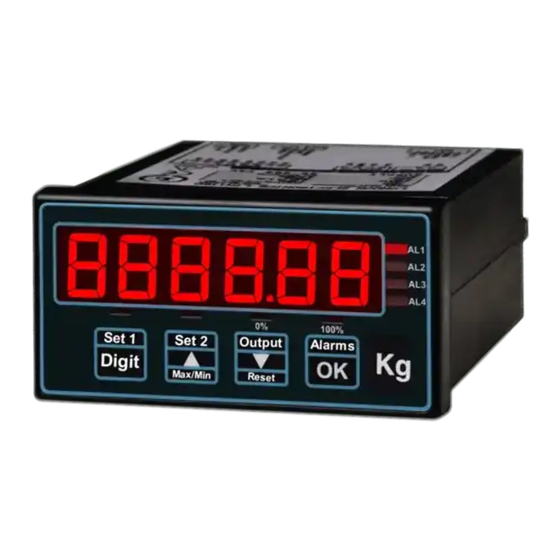
Panel mounting counter / frequency / rate meter
Connection details, scaling and general information
The New version of the INTUITIVE Family, with these extra benefits...
* External selection of debounce, pullup/pulldown and sensitivity
* 16 bit D/A convertor, greater analogue output resolution.
* More comms options, for faster, more flexible data access.
* Extra 'Factor and Offset' feature, allows you to correct for Gravity, Container Tare etc.
* Simpler Alarm-Setpoint setting.
* More alarm setting modes, including in-band and out of band alarms.
* Summary Screen, lets you know which options are fitted, whenever you want to know.
* Wider operating temperature range
* Variable brightness feature
* Adjustable menu timeout delay, to suit new and experienced users.
* Online streaming step-by-step video guides at http://london-electronics.com
INT2
= Intuitive Mark 2 family
C
= Counter / rate model
Analogue output:
Alarm outputs:
Serial data:
Display colour:
Power:
Document Ref:pm65\manuals\INTUITIVE_C_MkII
Thorncote Green, Near Hatch, Sandy, Bedfordshire SG19 1PU
Tel +44(0)1767 626444
www.london-electronics.com help@london-electronics.com
INTUITIVE-C Mk.2
!
0=none,
ANI=4-20mA,
0=none,
AL2= 2 relays,
0= none,
232=RS232,
R=Red,
G=Green
AC=100-240V AC,
DC=11-30V DC
Caution: There is a risk of electrical
shock if this instrument is not properly installed
Caution: Risk of danger: Read the whole
manual before you install this meter
Ordering code:
ANV=0-10V
AL4=4 relays
485=RS485
Revision:13 Dated: 30 June 2009
Fax +44(0)1767 626446
INT2-C-X-X-X-X-X
Software version F00.14
1
Advertisement

Related Manuals for London Electronics INTUITIVE INT2 Series


Summary of Contents for London Electronics INTUITIVE INT2 Series
- Page 1 London Electronics Limited Thorncote Green, Near Hatch, Sandy, Bedfordshire SG19 1PU Tel +44(0)1767 626444 Fax +44(0)1767 626446 www.london-electronics.com help@london-electronics.com Panel mounting counter / frequency / rate meter INTUITIVE-C Mk.2 Connection details, scaling and general information Caution: There is a risk of electrical...
-
Page 3: Table Of Contents
Contents Alarm board configuration Alarm programming 20-25 Analogue output 17-18 Basic meter startup settings Bootup routine Brightness Adjustment Button Functions 12-13 Connections Declaration of conformity General Description Input Configuration Introduction Keyboard timeout Delay Language Logic inputs Modes and Scaling Mounting and Installation Notes 29, 34-35 Option boards- installing... - Page 4 Warnings Please carefully read this manual and all warnings. Install the meter ONLY when you are sure that you’ve covered all aspects. Where the product is intended for “UL” installations, removal or addition of option boards is not permitted. Check that the model number and supply voltage suit your application before you install the meter.
- Page 5 Introduction Please contact us if you need help, if you have a complaint, or if you have suggestions to help us improve our products or services. If you contact us about a product you already have, please tell us the full model number and serial number, so that we can give you accurate and fast help.
- Page 6 General Description The INT2 Series of meters accept industrial sensors to allow various physical measurements to be made, such a weight, temperature, pressure, humidity etc. Different models are available for different sensor types. The main function of the INT2 series is to give a numeric readout of the variable being monitored.
- Page 7 Mounting and Installation - Class II Install the INT2 Series of meters in a suitable protective electrical control enclosure according to local wiring regulations. See specifications for maximum allowable temperature in enclosure. Allow adequate air circulation. Installing into front of panel 92mm +1mm -0mm Slide the meter, with gasket into the panel cutout...
- Page 8 Wiring Advice This meter uses detachable screw terminal connectors. Refer to the wiring diagram on the following page for the correct positioning of each wire. The conductors you use must be suitable for the meter’s temperature, current and voltage rating, which is broadly described as follows:- Cable Temperature Rating All cables must be rated for operation up to 90C continuous.
- Page 9 Connections - INT2-C R S 2 3 2 Connectors and options Connectors may be present R S 4 8 5 even if output options are not installed. Refer to rating label to see installed options. Rated 2A 250VAC Resistive Analog 0, 2 or 4 Alarm Relay Serial Data o/p option...
- Page 10 Basic startup meter Settings Lockout notes: Cal Lock switch = OFF when changing. Switch Cal Lock to ON after changing Menu Language Choice Press the two right hand buttons briefly. You will see the User Interface language, which you can change with the UP or DOWN buttons. Accept with OK UI EnG UI FRA Next you will see ...
- Page 11 Brightness Adjustment Lockout notes: Cal Lock switch = ON when changing. In normal operation, you can select from one of 8 brightness levels, to suit your local lighting conditions, or to match the brightness of several meters which may be from different batches or ages.
- Page 12 Button Functions- ‘Quick-Step’ - Page 1 Functions Buttons Conditions Alarm Settings A L C F G Can be viewed at any time. Press button briefly to view Alarm lockout OFF to change >3 seconds to change setpoint >5 seconds to change function Analogue Output Settings 888888 Calibration lockout OFF...
- Page 13 Button Functions- ‘Quick-Step’ - Page 2 Functions Buttons Conditions Filter time constant for Rate Fil 0.5 Calibration lockout OFF Press both buttons >3 secs Change with UP/DOWN button. OK=Accept Hardware & Software summary int C Can be viewed at any time Press both buttons >3 secs Input Configuration 1NP 1...
- Page 14 Modes and Scaling The INT-C2 has a number of useful operating modes. When you have chosen a mode, you can then scale the display . To select a mode, switch the lockout switch OFF and press the Set1 button for 3 seconds..t o t a l puls.in d i s p...
- Page 15 Input Configuration You can configure the inputs, using the buttons, to accept AC, DC or low level inductive pulses. You can also choose whether to have a pull-down or pull-up resistor (for PNP, NPN or contact closure inputs) and whether to include de-bounce filtering, to mimimise contact bounce effects.
- Page 16 How to install option boards Warning: Disconnect Where the product is intended for “UL” installations all power before exposing removal or addition of option boards is not permitted. the rear of the meter If you want to open your meter to install or modify option boards, follow these steps... Switch off power to the meter and unplug all connectors.
- Page 17 Analogue Output - page 1 Warning: Disconnect Where the product is intended for “UL” installations all power before exposing removal or addition of option boards is not permitted. the rear of the meter The analogue output board plugs onto the 0, 2 or 4 alarm upper option board. It plugs onto a pair of connectors and is secured by two snap-pillars.
- Page 18 Analogue Output - page 2 Lockout notes: Cal Lock switch = OFF when changing. Switch Cal Lock to ON after changing Your analogue output can cover 0-100% of its range over a display range which you can set. For example, you might want 4-20mA output, for a display range of 500 to 1000. You would press the Analogue O/P button for 3 seconds, and select 4-20mA Then set 0% = 500 Then set 100% = 1000...
-
Page 19: Alarm Board Configuration
Alarm Board Configuration Warning: Disconnect Where the product is intended for “UL” installations all power before exposing removal or addition of option boards is not permitted. the rear of the meter You can have 3 types of alarm board:- An alarm board with no relays, which will simply allow you to fit analogue and/or serial output options. -
Page 20: Alarm Programming
Alarm Programming Lockout notes: Alarm Lock switch = OFF when changing. Switch Alarm Lock to ON after changing Alarm lockout switch must be OFF. Press alarm button briefly to choose an alarm channel - look at the AL!, AL2, AL3 or AL4 leds to see which channel is selected. Then press the alarm button for 3 seconds to show the Setpoint window - you can now edit the setpoint value with the DIGIT, UP and DOWN buttons. - Page 21 Hi Alarm relay action, no Hysteresis Alarm tripped Alarm reset The alarm relay will activate when the measured value is at or above the setpoint value. The alarm relay will reset whe you fall below the setpoint value Set.Pt Value Alarm = Hi Setpoint = 69 Hysteresis = 0...
- Page 22 Lo Alarm relay action, no hysteresis Alarm tripped Alarm reset The alarm relay will activate when the measured value is at or below the setpoint value. The alarm relay will reset whe you rise above the setpoint value Set.Pt Value Alarm = Lo Setpoint = 43 Hysteresis = 0...
- Page 23 InFlight Hi Alarm relay The In-Flight alarm modes are used in applications where you want to accurately fill one container from another. If you were to simply close the shutoff valve when the weight reaches your desired amount, you would find thet the weight is higher than you’d Which mode should I use? hoped for.
- Page 24 InFlight Lo Alarm relay The In-Flight alarm modes are used in applications where you want to accurately fill one container from another. If you were to simply close the shutoff valve when the weight reaches your desired amount, you would find thet the weight is higher than you’d hoped for.
- Page 25 In-Band Alarm relay Alarm tripped Alarm reset The alarm relay will activate when the measured value is below the HI value and above the LO value HI Set.Pt Value LO Set.Pt Value Alarm = In.Bnd Hi = 69 Lo = 35 i n .
-
Page 26: Analogue Output
Serial Output - page 1 Warning: Disconnect Where the product is intended for “UL” installations all power before exposing removal or addition of option boards is not permitted. the rear of the meter The serial output board plugs onto the 0, 2 or 4 alarm upper option board. It plugs onto a pair of connectors and is secured by a snap-pillar. - Page 27 Serial Output - page 2 Lockout notes: Cal Lock switch = OFF when changing. Switch Cal Lock to ON after changing 100% OUTPUT ALARMS DIGIT B r i e f l y p r e s s t o g e t h e r Baud :- Select from 300,600,1200,2400,4800,9600,19200,38400, 57600,115200 dF = Data Format = 8n1, 7n1, 7E1, 701 Prot = Protocol = P1 (polled ASCII), P2 (Polled Modbus ASCII), C1 (Continuous), H1 (GPS)
-
Page 28: Logic Inputs
Logic Inputs and extra button functions Warning: Warning: Disconnect all power before Logic inputs are NOT isolated exposing the rear of the meter from input signal Lockout notes: Cal Lock switch must be ON to enable logic inputs. Peak and Valley Detection (Maximum/Minimum Reading View) The meter can store the lowest and highest reading values in memory. -
Page 29: Notes
Notes... -
Page 30: Reverse/Mirror/Heads-Up Display
Reverse/Mirror/Heads-Up display The INT2 display can be ‘mirror-imaged’ to allow it to be viewed as a reflection in a rear-view mirror, windscreen or other reflective surface. This can be useful for creating ‘heads-up’ displays, for some test installations where the dis- play will be veiwed in a mirror, as a display for drivers reversing large vehicles, etc. -
Page 31: Specifications
Equipment Specifications Bezel size 48mm high by 96 mm wide (1/8 DIN) Panel Cutout 45 mm high by 92 mm wide Case Depth 125 mm including connectors Weight 300 grammes Case Material Black polycarbonate Connectors Detachable Screw Terminal connectors Environmental Storage Temperature range -20 to +70C, non condensing Operating temperature range 0 to 50C, non condensing Front sealed IP65. - Page 32 Record of revisions 1 May 2007 INT-L Released with F00.001 software 22 May 2007 Added RS485 logic level diagram 22 August 2007 Added Zener barrier application notes. 2 October 2007 F00.006 software. Linearisation added. Inflight compensation and band alarms added. Brightness setting added, Menu timeout delay added.
-
Page 33: Weee
Waste Electrical and Electronic Equipment (WEEE) In Europe, this equipment must be disposed of in accordance with European Parliamentary Directive 2002/96/EC This directive encourages recycling and the reduction of waste materials in the environment. This means it must be sent to an approved recycling plant if you want to dispose of it. It must not be thrown away in general rubbish. - Page 34 Notes...
- Page 35 Notes...
- Page 36 Signal cabling shall be routed separately to power carrying cabling (includes relay output wiring) All signal cabling shall be screened. The screen shall only be terminated to the power earth terminal Declared as true and correct, for and on behalf of London Electronics Ltd. J.R.Lees Director...
Need help?
Do you have a question about the INTUITIVE INT2 Series and is the answer not in the manual?
Questions and answers