Advertisement
Quick Links
Advertisement

Subscribe to Our Youtube Channel
Related Manuals for Veratron LINK UP J1939


Summary of Contents for Veratron LINK UP J1939
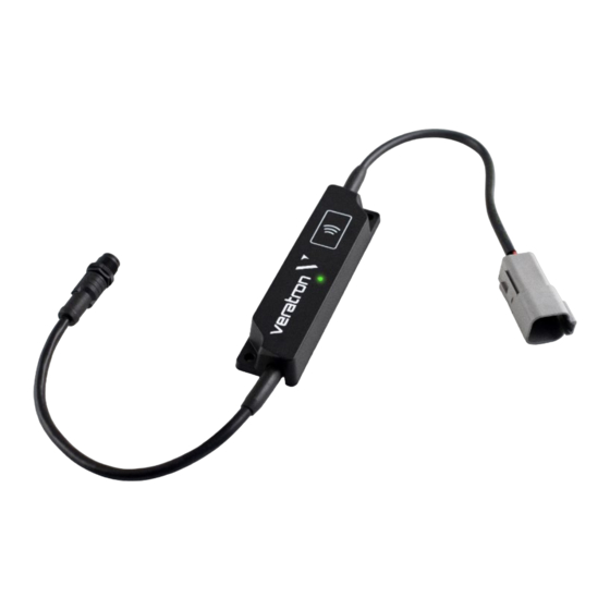
- Page 1 LINK UP GATEWAYS SERIES LINK UP J1939 OPERATING INSTRUCTIONS rev. AA B001030...
-
Page 2: Table Of Contents
CONTENT CONTENT Introduction Safety information System installation Configuration Technical data B001030... -
Page 3: Introduction
Link Up configurator App. THE LINK UP GATEWAY CONCEPT The Link Up J1939 (hereinafter “Device” or “Link Up”) Configuring LinkUp gateways is simple using a mobile provides an easy method to convert engine or vessel device and the companion LinkUp Configurator App for information to NMEA 2000. -
Page 4: Safety Information
• Use our product only as intended. Use of the product • Modifications or manipulations to veratron products for reasons other than its intended use may lead to can affect safety. Consequently, you may not modify or personal injury, property damage or environmental manipulate the product! damage. - Page 5 SAFETY INFORMATION • When working underneath the vehicle, secure it vehicle/machine or boat. Use of conventional test lamps can cause damage to control units or other according to the specifications from the vehicle electronic systems. manufacturer. • • Drill small ports; enlarge and complete them, if The electrical indicator outputs and cables connected to them must be protected from direct contact and necessary, using taper milling tools, saber saws, keyhole...
-
Page 6: System Installation
SYSTEM INSTALLATION SYSTEM INSTALLATION WARNING Before beginning, disconnect the negative terminal on the battery, otherwise you risk a short circuit. If the vehicle is supplied by auxiliary batteries, you must also disconnect the negative terminals on these batteries! Short circuits can cause fires, battery explosions and damages to other electronic systems. Please note that when you disconnect the battery, all volatile electronic memories lose their input values and must be reprogrammed. - Page 7 SYSTEM INSTALLATION CONNECT TO THE J1939 NETWORK SAE J1939 is a common CAN bus standard. CAN buses are used to connect the different sensors, monitors and other Turn on the circuit breaker (for some models the electrical components of a machine, and digitally transmit ignition also should be on) and measure the voltage the required data in between those components.
- Page 8 SYSTEM INSTALLATION CONNECT TO THE NMEA 2000® NETWORK Once the Link Up Gateway is mounted complete, it is possible to interface it to the NMEA 2000® backbone through the dedicated plug. Please ensure to tighten the M12 connector by screwing it onto its counterpart, so to preserve the water tightness.
-
Page 9: Configuration
SYSTEM INSTALLATION CONFIGURATION LINK UP CONFIGURATOR APP To configure your system, some parameters must be This is possible through the “Link Up Configurator” calibrated through the Link Up gateway. These parameters smartphone App, which can be downloaded free of charge are: from the stores of both Android and iOS devices. - Page 10 CONFIGURATION 2. After the readout, the App will show the “Configuration Summary”, which displays all the current settings of the device. To modify the configuration, press the “Change Configuration” button. 3. Select whether you’ve got one or two engines on your vessel. Then choose for each engine its source number that is used in the J1939 system as well as the instance which should be used in the NMEA...
- Page 11 CONFIGURATION 4. After that, you can choose, which alarms you want to show up on your dashboard. Once the settings are completed, press the “Write Configuration” button to prepare the download. See the “Supported Alarms” section of this manual for the complete list of supported alarms.
- Page 12 CONFIGURATION SUPPORTED DATA The Link Up J1939 is able to translate the following information: CAN J1939 NMEA 2000 Data Data Engine Speed EEC1 Engine Speed 127488 Engine Hours HOURS 247 Total Engine Hours 127489 Engine Load EEC2 Engine Percent Load...
- Page 13 CONFIGURATION SUPPORTED ALARMS Alarm Check Engine Low Fuel Delivery Pressure Water in Fuel Low Oil Level Low Oil Pressure High Tc Boost Pressure High Air Inlet Pressure High Coolant Temperature Low Coolant Level Low Transmission Oil Level Low Transmission Oil Pressure Low Electrical Potential High Exhaust Gas Temperature High Oil Temperature...
-
Page 14: Technical Data
TECHNICAL DATA TECHNICAL DATA LINK UP DATASHEET Operating voltage 6 – 16.5 V Nominal voltage 12 V (from NMEA 2000® network) Power consumption ≤ 100 mA NMEA 2000® LEN Operating temperature -30°C to 80°C Sensor cable length 25 cm NMEA 2000® cable length 25 cm CAN J1939-Network plug Deutsch DT04-6P (Male) - Page 15 TECHNICAL DATA DIMENSIONS PINOUT Pin No. Description Shield NET-S (V+) NET-C (V-) NET-H (CAN H) NET-L (CAN L) Micro-C M12 5 poles plug Male, product side view B001030...
- Page 16 TECHNICAL DATA Pin No. Wire color Description Blue CAN Lo N.C. White CAN Hi Black N.C. Deutsch DT04-6P plug, front view KL. 15 – Power (12V) B001030...
- Page 17 AG, except for the following actions: • Printing the document in its original format, totally or partially. • Copying contents without any modifications and stating veratron AG as copyright owner. Veratron AG reserves the right to make modifications or improvements to the relative documentation without notice.
Need help?
Do you have a question about the LINK UP J1939 and is the answer not in the manual?
Questions and answers