
Subscribe to Our Youtube Channel
Related Manuals for ACKERMANN 16-2050


Summary of Contents for ACKERMANN 16-2050
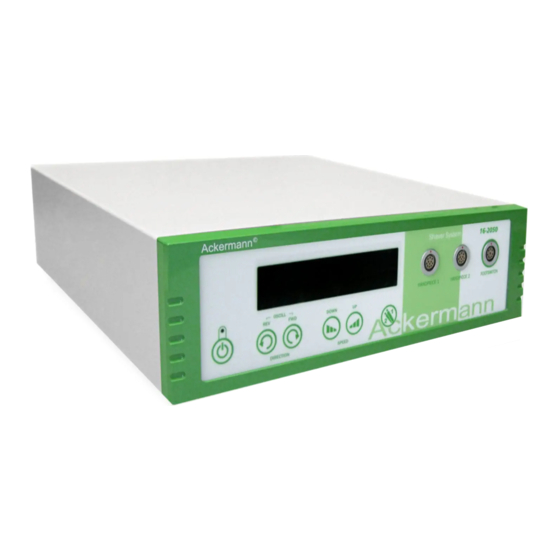
- Page 1 Ackermann SHAVER SYSTEM User Manual Arthroscopy Shaver System • Arthroscopy Shaver System #16-2050 • Handpiece #16-2050-100 • Footswitch #16-2050-200 www.ackermannsurgical.com...
-
Page 2: Table Of Contents
Ackermann SHAVER SYSTEM CONTENTS 1. Precautions 2. Classification of the device and its intended use 2.1. Intended use of the device 2.2. Contents of standard package, optional accessories 2.3. Device classification 3. Description of components 3.1. Front panel description 3.2. Rear panel description 3.3. -
Page 3: Precautions
Ackermann SHAVER SYSTEM 1. PRECAUTIONS IMPORTANT • The operating instruction shows how to operate, maintain and service the equipment, so that its working life is as long as possible. Proper service is essential for a long-term trouble-free operation of the device. • Staff operating the device should familiarise themselves with the contents of this manual before installation and use of the device, and those who have access to it. • The device can only be operated by doctors or assisting staff with appropriate qualifications. • The device is made up in I safety class. • CAUTION: To avoid risk of electric shock the device has to be connected only to a supplying network with protective earthing. • Before connecting the device to the power outlet, make sure that the parameters of the power grid are identical to those in the device specifications. Supply voltage, frequency and power consumption are specified in the remainder of... -
Page 4: Classification Of The Device And Its Intended Use
Table 1. Shaver System variants: Pos. Shaver System Components of Shaver System Set Control Unit incl. Handpiece with manual lock and standard # 16-2050 Footswitch The device can be used only for treatment, such as: arthroscopy. It is the user’s responsibility to use the device properly as intended. Not complying to the operating instruction may result in danger for the patient or any of users. 2.2. CONTENTS Of STANDARD PACkAGE, OPTIONAl ACCESSORIES Table 2. -
Page 5: Description Of Components
Ackermann SHAVER SYSTEM Medical electrical equipment -- Part 1-6: General requirements for basic safety EN 60601-1-6 and essential performance - Collateral standard: Usability EN ISO 62366 Medical devices -- Application of usability engineering to medical devices EN ISO 62304 Medical device software - Software life cycle processes Sterilization of medical devices -- Information to be EN ISO 17664 provided by the manufacturer for the processing of resterilizable medical devices Biological evaluation of medical devices -- Part 1: EN 10993-1 Evaluation and testing within a risk management process Biological evaluation of medical devices -- Part 18: Chemical characterization of... -
Page 6: Rear Panel Description
Ackermann SHAVER SYSTEM 9. “SPEED UP” button: stepwise increase of the speed to the next higher level of rotational speed. 10. “TOOl” button: function key which enables switching between two connected tools. It is available only if both tools are present in sockets “HANDPIECE 1” and “HANDPIECE 2”. 11. “STANDBY” lED: illumination corresponds to the following states: • the “Standby” LED blinks at a frequency of 0.5Hz - this means that the device is in a “Standby” state, • the “Standby” LED illuminates continuously - the device is switched on and working properly. 12. Rubber feet of the device 3.2. -
Page 7: Handpiece Description
Ackermann SHAVER SYSTEM 3.3. hANDPIECE DESCRIPTION 20. Receiving ring of the handpiece: the shaver blades are securely engaged when the locking device has snapped shut visibly and clicking sound can be heard. The shaver blade cannot be released, not even after repeated pulling. 21. Valve control: to regulate the extraction of saline solution from the operative site. 22. Casing of handpiece 23. Aspiration port: when the tube of the vacuum pump is mounted onto this nozzle, the saline solution is sucked off through the Handpiece. -
Page 8: Footswitch Description
Ackermann SHAVER SYSTEM 3.4. fOOTSWITCh DESCRIPTION Page: 8 // 28... -
Page 9: Installation And Starting The Device
Ackermann SHAVER SYSTEM 30. REv: pedal button to switch the shaver blade in the Handpiece to anti-clockwise rotation. The number of rotations depends on the set speed which can be adjusted via the Unit Control buttons (8) and (9) or Footswitch button (34). 31. OSCIllATION: pedal button to switch to oscillating mode. The number of rotations depends on the set speed which can be adjusted via the Control Unit buttons (8) and (9) or Footswitch button (34). The oscillation frequency depends on settings. 32. FWD: pedal button to switch the shaver blade in the Handpiece to clockwise rotation. The number of rotations depends on the set speed which can be adjusted via the Control Unit buttons (8) and (9) or Footswitch button (34). 33. TOOL: pedal button to initiate the change function of the steerable device “HANDPIECE 1” (2), “HANDPIECE 2” (3) connected to the Control Unit. 34. SPEED: pedal button to regulate the speed of the shaver blade in the Handpiece during use. Each time the button is pressed, the speed is increased to the next higher level. -
Page 10: Basic Settings
Ackermann SHAVER SYSTEM • connect the power cord provided with the device to the socket (16) on the back of the Control Unit, • plug the power cord into the power socket. The voltage should be within the range indicated on the device label. Turn on the device: • A properly installed and connected device should be started using the “ON/OFF” switch (15) located on the rear panel. The “STANDBY” button (5) will start flashing at a frequency of 0,5Hz, indicating that the device has switched to standby mode. 4.2. BASIC SETTINGS • Once the device is in standby mode (see chapter 4.1.), press simultaneously and hold down the “SPEED DOWN” (8) and “SPEED UP” (9) buttons with your right hand. • Still holding buttons (8) and (9) briefly press the “STANDBY” button (5) with your left hand. • Once you are in the required menu, you can release these buttons. You can now select the language you require. The last selected language is shown. To change the language, press buttons “SPEED DOWN” (8) or “SPEED UP” (9). The user can choose between German, English, French, Russian, Polish and Turkish. The selected language must be confirmed by pressing the button “TOOL” (10). -
Page 11: Connection Of Wired Footswitch To Control Unit
Ackermann SHAVER SYSTEM The maximum speed for Shaver System is 8000 rpm. Attention: Handpieces must have come to a standstill before they can be removed from the socket (2) and/or (3) of the Control Unit. Hold Handpieces only by their case (22) during use. 4.4. CONNECTION Of WIRED fOOTSWITCh TO CONTROl UNIT • The plug (38) at the end of the Footswitch cable has to be connected to the “FOOTSWITCH” (4) socket at the front panel of the Control Unit. Only one Footswitch can be connected. • The plug (38) of the Footswitch is marked with a notch and a red dot. When connecting the plug, make sure that the red dot on the plug is in the same position as the red dot on the socket (4) of the Control Unit. The pins inside the plug might otherwise get damaged during connection. • To avoid damage, make sure to pull at the plug (38) itself and not the cable when removing the plug. When the Control Unit is activated (see chapter 4.6.), the Handpiece can be operated via the Footswitch. 4.5. CONNECTION Of WIRElESS fOOTSWITCh TO CONTROl UNIT • The plug (38) has to be connected to the “FOOTSWITCH” (4) socket at the front panel of the Control Unit. Only one... -
Page 12: Starting The Device
Ackermann SHAVER SYSTEM 4.6. STARTING ThE DEvICE • Once the device is in standby mode (see chapter 4.1.), press the “STANDBY” button (5). The main display (1) will display the logo and the model of device and all buttons of the interface or the “STANDBY” LED will be lit continuously. Device is ready to work. “Ready” mode. 5. OPERATION Of ThE COMPONENTS 5.1. CONTROl UNIT Unauthorized removal of the seal voids all warranty claims and results in the manufacturer disclaiming all liability for subsequent defects and/or restrictions of use. The same applies if the handpiece and the footswitch are opened by unauthorized personnel. -
Page 13: Handpiece With Automatic Receiving Ring Of The Shaver Blades
Ackermann SHAVER SYSTEM 5.3.1. hANDPIECE WITh AUTOMATIC RECEIvING RING Of ThE ShAvER BlADES Please adhere to the following steps when locking the shaver blades into the Handpiece: • Insert the shaver blade into the opening of the Handpiece until you can feel resistance. The shaver blade is properly engaged when you can hear a clearly audible sound and the instrument cannot be removed, even by pulling. -
Page 14: General Information
Ackermann SHAVER SYSTEM In addition to the above, the country specific legal provisions regarding reprocessing of medical devices have to be observed! Safety precautions! Always wear protective clothing during the reprocessing of contaminated medical instruments, i.e. eye and mouth protectors, chemical-resistant gloves and moisture repellent clothes. Blood, residual tissues and other infectious materials pose an increased risk of infection. -
Page 15: Mechanical Cleaning And Disinfection
Ackermann SHAVER SYSTEM with the receiving ring (20) facing downwards. The Handpiece and the cable must be completely covered by cleaning solution. The valve control (21) must be set in MAX position, when choosing the cleaning solution, make sure that: • the solution is suitable for cleaning instruments with metal and plastic components, • all chemicals contained in the solution are compatible with the medical devices (see chapter 6.3.9 material compatibility), • the solution is suitable for ultrasonic baths (i.e. no foaming). 5. Rinse the entire Handpiece. Rinse all lumina, e.g. the suction channel and the closing mechanism of the receiving ring with a water pistol with cold water for at least 10 seconds (static water pressure: 3.8 bar). Make sure that the valve control... -
Page 16: Manual Cleaning And Disinfection
Ackermann SHAVER SYSTEM 5. Once the entire cycle is completed, remove the Handpiece from the washer /disinfector. 6. Check the Handpiece to make sure that it is ready for use. Wrap immediately after removal from the washer /disinfector (see chapter 6.3.5 Inspection/lubricants and 6.3.6 Packaging). If the Handpiece is still wet, dry at a clean place. The suitability of these medical devices for effective mechanical cleaning and disinfection was tested and proved by an independent test laboratory. -
Page 17: Sterilization
Ackermann SHAVER SYSTEM • suitable for steam sterilization (heat resistant up to 141°C, sufficient permeability), • the Handpiece is adequately protected from mechanical damage, • sterilization containers must be serviced in regular intervals according to the instructions of the manufacturer. 6.3. 7. STERIlIzATION Use the below described method of sterilization only. All other methods are prohibited. Steam sterilization: • fractionated vacuum and gravitation method (with sufficient drying time (at least 10 minutes)). The gravitation method is less effective and should only be used if no fractionated vacuum is available, • steam sterilizer according to DIN EN 13060/DIN EN 285, • validated according to ISO 17665 (previously DIN EN 554/ ANSI AAMI ISO 11134) (Start-up and product specific performance assessment), • the temperature during sterilization must not exceed 138°C (280°F plus tolerance) according to DIN EN ISO 17665... -
Page 18: Reusability
Table 5. Values of fuses intended for specific models of the Control Unit of Shaver System: Pos. Type of Control Unit value and type of fuse # 16-2050 2x T 1,25A L 250 V • Slide the fuse drawer (17) into the power socket of the device (16). Proper installation will be signalled by an audible “click” , the sound of latches closing in the drawer locking mechanism. -
Page 19: Warranty And Post-Warranty Service
Ackermann SHAVER SYSTEM The inspection consists of: • checking the technical state of the device, • cleaning the interior of collected dust and other contaminants, • measurement of operational parameters, • performance of an electrical safety test in accordance with EN 60601-1, • software update. Each inspection involves a subsequent report, whose copy will be delivered to the client with the device. If malfunctions are found during the inspection, the inspector will prepare an offer for removal of such defects, which will be sent to the customer by e-mail or fax. 7.3. WARRANTY AND POST-WARRANTY SERvICE The device manufacturer provides warranty and post-warranty service under the following conditions: • a damaged device should be sent in its original packaging directly to manufacturer (address can e found in last page Manufacturer and service provider data) or to local manufacturer’s distributor, together with a detailed description of... -
Page 20: Technical Specifications
Ackermann SHAVER SYSTEM 2: The handpiece does not work Issue Solution Connect the Handpiece to the socket “HANDPIECE 1 (2) or The Handpiece was not connected to the Control Unit “HANDPIECE 2”(3) or check that the Handpiece is properly locked in place connect the Footswitch to the socket “FOOTSWITCH” (4) or check The Footswitch was not connected to the Control Unit that the Footswitch is properly locked in place activate the socket for the required Handpiece by pressing the The other Handpiece is activated “TOOL”(10) button at the Control Unit 3: The footswitch does not work Issue Solution Blade is blocked in the Handpiece... - Page 21 Ackermann SHAVER SYSTEM Weight 5.1 kg External dimensions D: 306 mm x W: 330 mm x H: 96 mm Fuses According to Table 5 During operation: +10°C to +40°C Ambient temperature During storage and transport: -20° C to +45°C During operation: 70% Maximum relative humidity During storage and transport: 70% Protection against harmful ingress of water or particulate or IP X0 , Not protected against water / moisture particulate matter Do not use in the environment of flammable anesthetic gases.
-
Page 22: Symbols Used On Labelling
Ackermann SHAVER SYSTEM Table 9. Footswitch technical specification, depending on the device variant: Parameter Footswitch Type of footswitch standard standard wireless Weight 2.45 kg 2.2 kg Cable length wireless + receiver lithium-polymer accumulator, Battery type not to be replaced by the user... -
Page 23: Disposal Of Used Electronic Products
10. INfORMATION ABOUT POTENTIAl ElECTROMAGNETIC INTERfERENCES Table 11. Guidance and manufacturer’s declaration – electromagnetic emissions: EMC – guidance and manufacturer’s declaration (EN 60601-1-2: 2007) Arthroscopy Shaver System 16-2050 The Arthroscopy Shaver System is intended for use in the electromagnetic environment specified below. The customer or the user of the Arthroscopy Shaver System should assure that it is used in such environment. - Page 24 Ackermann SHAVER SYSTEM The Arthroscopy Shaver System is suitable for use in all establishments, including domestic establishments and directly RF emissions CISPR 11 50/60 Hz connected to the public low-voltage power supply network that supplies buildings used for domestic purposes. Harmonic emissions Class A IEC 61000-3-2 Voltage fluctuations Consistent IEC 61000-3-3 Table 12. Guidance and manufacturer’s declaration – Electromagnetic immunity: The Arthroscopy Shaver System is intended for use in the electromagnetic environment specified below. The customer or the user of...
- Page 25 Ackermann SHAVER SYSTEM NOTE: U is the mains voltage prior to application of the test level. Table 13. Guidance and manufacturer’s declaration – Electromagnetic immunity: The Arthroscopy Shaver System is intended for use in the electromagnetic environment specified below. The customer or the user of the Arthroscopy Shaver System should assure that it is used in such environment.
-
Page 26: Appendix
NOTE 2: These guidelines may not apply in all situations. Electromagnetic propagation is affected by absorption and reflection from structures, objects and people. 11. APPENDIX All product codes covered by these instructions are listed below: • Shaver System Set #16-2050 • Handpiece with manual lock #16-2050-100 • Shaver standard footswitch #16-2050-200 Page: 26 // 28... -
Page 27: Contact Details
Ackermann SHAVER SYSTEM 12. CONTACT DETAIlS Ackermann Instrumente Gmbh Eisenbahnstrasse 65-67 78604 Rietheim-Weilheim Germany Phone: +49 (0)7461 966 17 - 0 Fax: +49 (0)7461 966 17 - 70 E-Mail: sales@ackermannsurgical.com Web: www.ackermannsurgical.com End of document Page: 27 // 28... - Page 28 Ackermann 0483 Ackermann Instrumente Gmbh Eisenbahnstrasse 65-67 78604 Rietheim-Weilheim Germany User_Manual-16-2050-Revision_05/21 Copyright by Ackermann Instrumente GmbH. Specifications, design and accessories in this user manual are subject to change without any notice or obligation on the part of the manufacturer.
Need help?
Do you have a question about the 16-2050 and is the answer not in the manual?
Questions and answers