
Subscribe to Our Youtube Channel
Related Manuals for ACKERMANN Fusion 16-2091


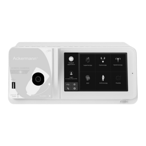
Summary of Contents for ACKERMANN Fusion 16-2091
- Page 1 Ackermann SHAVER SYSTEM User Manual Endoscopic Camera System • Ackermann Fusion™ FullHD 3CMOS NTSC/PAL Camera #16-2091 www.ackermannsurgical.com...
-
Page 2: Table Of Contents
Ackermann ENDOSCOPIC CAMERA SYSTEM CONTENTS 1. Preface 2. Introduction of the unit 3. Safety instructions 4. Regulatory advice 4.1. Compliance 4.2. Electromagnetic interferences and electrostatic discharge 4.3. Medical device vigilance 4.4. End of lifecyle 5. Installing the unit 5.1. Connections 5.2. -
Page 3: Preface
Ackermann SHAVER SYSTEM 1. PREFACE We thank you for your purchase of the Ackermann Fusion™ Endoscopic Camera System. In order to make the best use of it while having all the necessary precautions at your disposal, it is essential for you to become acquainted with this manual. The sentences displaying the symbol correspond to points requiring special attention. The sentences displaying the symbol represent items of information. To facilitate installation and use of the device, we have attempted to make the device manual more practical. -
Page 4: Regulatory Advice
• Prior to plugging in the device, check that the mains voltage and mains frequency indicated on the device correspond to the power system values • Prior to activation, ensure that neither the device nor the power cable is damaged. Deteriorated cables and connectors must be replaced immediately • Do not drop the device. If the device falls, do not reconnect the device but send it back to youruthorised distributor or directly to the Ackermann after-sales service department • No additional multiple-socket outlets or extension cords must be connected to the EM system To avoid any risk of electrical shock, this device must be connected only to a power system equipped with protective grounding Devices connecting to the input/output ports must comply with the IEC 60950-1 standard Any modification of this device without authorisation from the manufacturer is prohibited. If the medical device... -
Page 5: Electromagnetic Interferences And Electrostatic Discharge
Ackermann SHAVER SYSTEM 4.2. ELECTROMAGNETIC INTERFERENCES AND ELECTROSTATIC DISCHARGE Although this product complies with CEM standards, it may in very special circumstances interfere with other devices, or itself be the object of interference from other devices or an unfavourable electromagnetic environment. Image transfers from the camera to a monitor may be susceptible to electromagnetic disturbances and electric system disturbances. In order to avoid these situations, it is advisable to: • Ensure of the quality of the electric power system (especially the grounding of all devices and medical carts •... -
Page 6: Activation
• If needed, connect other monitors or peripherals, preferably using the HDSDI output ports C8 > HDSDI output ports produce an interleaved 1080 signal > HDSDI output ports are preferred when a very long cable is necessary • Turn the activation switch S2 to position “1” > The camera takes about 30 seconds to come on. The Ackermann logo is displayed on the screen during this interval > The flashing LED standby button, and the appearance of “standby” on the screen indicate that the camera is properly activated • Connect the camera head to the control unit via the dedicated connector C1 • Touch the screen, OR press the Standby button to access the main menu... -
Page 7: Activation Of The Device With A Fusion Card
5.3. ACTIVATION OF THE UNIT WITH A FUSION CARD Scan a Fusion Card on the read area provided on the lexan housing (next to the Ackermann logo) • Scanning a standard Fusion Card: > Activate the camera directly on the surgical screen, in the surgical application corresponding to the Fusion Card scanned •... -
Page 8: White Balance
Ackermann ENDOSCOPIC CAMERA SYSTEM Below is the comprehensive list of the configurable functions: Short press Long press No action No action Brightness + Brightness + Brightness - Brightness - Light source - Intensity + Light source - Intensity + Peripheral 1 Peripheral 1 Peripheral 2 Peripheral 2 Mirror Mirror Freeze frame Freeze frame Recording images on the camera (if equipped with an integrated... -
Page 9: Focusing
Ackermann SHAVER SYSTEM • Set the white balance; the BALANCING IN PROGRESS message is displayed on the screen • Continue to film the white surface until the BALANCE OK message is displayed on the screen Note 1: Setting the white balance causes the chronometer to be activated, signalling the start of the surgery and therefore the availability of additional functionalities, particularly those linked to the image quality settings Note 2: If the Ackermann light source is connected to the Ackermann camera by the communication cable supplied, then setting the white balance will cause the LED to light up if it was previously off In the event that the white balance is set during an operation, i.e. inside the patient, the endoscope must be pulled out of the trocar and the white balance must be set again using gauze 6.4. FOCUSING Once the endoscope is connected and the light source is activated, slowly turn the lens focus ring to find a position where the objects being observed are sharp. Focusing on a fairly distant point helps obtain adequate field depth for the operation and therefore avoids having to do retouching too regularly 6.5. FUNCTIONALITIES 6.5.1. VIDEO SETTINGS Once the white balance is set, or the “Start” button has been pressed, access to the video settings is authorised. In this way, it is possible to work directly on brightness, sharpness and red gain. Additional settings are available by clicking the “More settings” button. The following parameters can be modified: Brightness This parameter varies the general brightness of the image Blue gain Colorimetry shift from white to blue Red gain Colorimetry shift from white to red... -
Page 10: Other Parameters
Ackermann ENDOSCOPIC CAMERA SYSTEM Red phase Colorimetry phase shift from Orange to Magenta Click the “Close settings” button once to return to the previous menu. 6.5.2. OTHER PARAMETERS HD Recording: If your camera is equipped with an integrated HD recorder, you can set HD image / video recording from the interface menu using the corresponding buttons or from the buttons on the camera head if these have been programmed accordingly. Insufflators: If your camera is connected to the Fusion insufflator via the communication cable provided, you can select from the parameters menu whether or not to display information about the operating status of the insuffl ators on the surgical monitor’s OSD. -
Page 11: Connections Menu
Note: The icon for this menu changes to orange when at least one of the products on the system is disconnected. 6.10. CREATING USER PROFILES • Click the “Log in or create a profile” button • Click the “Create a profile” button > Activating the camera with a blank Fusion Card gives direct access to the following stage • Click the text field and enter the desired profile name • Click the “Return” button • Select a surgical speciality. This will form the basis for the video parameters • Click the “Create a profile” button OR scan a blank Fusion Card on the area provided for this purpose on the lexan housing (next to the Ackermann logo) • A message is displayed for a few seconds indicating that the device supports the creation of a profile • You can then: > Rename the profile and/or the preset by clicking the “Manage” button > Delete one (of the) profile preset(s) by clicking “Manage” > Use the preset created by clicking on it > Log out by clicking the “Log out” button Notes: If a blank Fusion Card has been scanned at least once (during activation and/or while saving a created profile), then the profile (and the presets) created will be automatically linked to this Fusion Ccard. A padlock icon will be displayed on this profile. This means that:... -
Page 12: Peripheral Outputs
Ackermann ENDOSCOPIC CAMERA SYSTEM 7.3. PERIPHERAL OUTPUTS Two (2) peripheral output ports are available C12 and these are used with a 3.5 mm jack lead for managing two peripherals (for example: a printer and a video recorder) from the buttons on the camera head. The devices connecting to the “VIDEO OUT” and “PERIPHERAL” ports must be compliant with standard IEC 60950. 7.4. KEYS & SYMBOLS ON THE FRONT & BACK PANELS The keys and symbols on the back panel are for identifying the camera in accordance with international standards IEC 60601-1, IEC 60601-2-18, IEC 60417 and EN 980 (See Appendix 1) The table below describes the back and front components: Connector for the camera head Main power socket RS232 output Service line RGBS video output DVI-D video output Ethernet output... -
Page 13: Suggested Decontamination Procedures
Ackermann SHAVER SYSTEM 8. SUGGESTED DECONTAMINATION PROCEDURES Disinfecting the camera control unit The camera control unit is a non-heat-resistant medical device and does not withstand immersion; consequently, it should be disinfected using a non-woven medium saturated with a disinfectant detergent This device is not drip-proof. Do not splash liquid on this product As decontamination is linked to the products, methods and/or tools used, decontamination is the sole responsibility of the staff concerned The device must always be disconnected before any cleaning procedure is carried out This device is not autoclavable Existing alkaline solutions for the disinfection of certain medical devices are NOT RECOMMENDED for disinfecting... -
Page 14: After-Sales Service And Maintenance
Ackermann ENDOSCOPIC CAMERA SYSTEM Disinfecting the lens surfaces A dirty lens surface can interfere with observation. The lens surface must not have any marks or smudges. To avoid scratching the lens surface, never use abrasive cloths or sponges to clean it To remove dust, dirt and other impurities not originating from the patient, wipe clean with a soft , lint-free cloth moistened with ethanol or 70% iAckermannpyl alcohol. When cleaning, wear gloves for protection from chemical products. Ensure that the equipment is completely dry before use. Use soft non-woven cloths to clean the lenses so as to avoid scratching them. -
Page 15: Technical Characteristics
Ackermann SHAVER SYSTEM • Check the lens setup If there is no image or if the image is not displayed, unplug and re-plug your device or reset the camera to the factory settings The image is extremely light or dark: • Check that the BRIGHTNESS parameter is not at the maximum or minimum setting • Check that the APERTURE used is not too wide or too narrow • Check that the camera head is correctly connected to the control unit •... -
Page 16: Electromagnetic Compatibility
Ackermann ENDOSCOPIC CAMERA SYSTEM • Compliant with international standards IEC 60601-1; IEC 601-2-18; IEC 60417 and EN 980 • Dimensions (W x H x D): 310 x 136 x 385 mm • Control unit weight: 4300g • Electric power supply: 100 - 230 VAC @ 50 Hz-60 Hz • Electricity consumption: 38-50 VA • Two T2.5AL - 250V fuses (Marked UL/CSA only) • Continuous operation Camera head • CF-type applied part •... -
Page 17: Cable Length
Ackermann SHAVER SYSTEM 12.1. CABLE LENGTH Cables and accessories Maximum length Test type In compliance with RF emission CISPR 11, Class B CISPR 11, Class B Harmonic current emission IEC 61000-3-2 Voltage changes and flicker IEC 61000-3-3 Electrostatic discharge immunity IEC 61000-4-2 Video cables Transient electromagnetic immunity IEC 61000-4-3 Mains cable < 3 meters Mains boundary cable Electrical fast transient/burst immunity IEC 61000-4-4... -
Page 18: Magnetic And Electromagnetic Immunity
Ackermann ENDOSCOPIC CAMERA SYSTEM Disrupting voltage on the power Class B terminals (Conducted emis- The EMISSIONS characteristics of this device allow it to be used in industrial sions) (CISPR 11) areas and in hospital environments (class A defined in CISPR 11). When it is used in a residential environment (for which class B defined in CISPR 11 is normally required), this device may not off er adequate protection for radio Harmonic current emission Conforming frequency communication services. (IEC 61000-3-2) The user may need to take corrective actions, such as relocating or redirect- ing the device. -
Page 19: Electromagnetic Immunity, Radiofrequencies
Ackermann SHAVER SYSTEM 12.5. ELECTROMAGNETIC IMMUNITY, RADIOFREQUENCIES The medical device is designed for use in the magnetic and electromagnetic environment described in the table below. The user and/or installer must ensure conformity of the electromagnetic environment. Immunity test Test level Conformity level Electromagnetic environment / comments CAUTION: RF mobile communication devices (including peripherals such as antenna cables and external antennas) should not be used nearer than 30 cm (12 inches) from any part of the medical device, including the cables specified by the manufacturer. If this is not respected, the performance of these devices may be impaired. Radiated radiofrequency 10 V/m 10 V/m A professional healthcare electromagnetic field 80 MHz at 2.7 GHz... -
Page 20: Symbols
Ackermann ENDOSCOPIC CAMERA SYSTEM 13. SYMBOLS Symbol Description Button Screen Socket Label (rear panel of the unit) For medical devices, this symbol is associated with the year of manufacture. The latter is denoted by four figures For medical devices, this symbol is associated with the name and address of the manufacturer Protective grounding Class 1 product Compliant with European directive 93/42/CEE An equipotential grounding socket conductor other than protective grounding or a neutral conductor, for direct connection between the electrical equipment and the potential equalisation busbar. Kindly refer to standard IEC 60601-1, 3rd edition... -
Page 21: Appendix
Ackermann SHAVER SYSTEM 14. APPENDIX All product codes covered by these instructions are listed below: • Ackermann Fusion™ FullHD 3CMOS NTSC/PAL Camera incl. CCU, USB Recording/Archive and 15-35 mm Coupler #16-2091 15. CONTACT DETAILS Ackermann Instrumente GmbH Eisenbahnstrasse 65-67 78604 Rietheim-Weilheim Germany Phone: +49 (0)7461 966 17 - 0 Fax: +49 (0)7461 966 17 - 70 E-Mail: sales@ackermannsurgical.com... - Page 22 Ackermann 0483 Ackermann Instrumente GmbH Eisenbahnstrasse 65-67 78604 Rietheim-Weilheim Germany User_Manual-16-2091-Revision_11/21 Copyright by Ackermann Instrumente GmbH. Specifications, design and accessories in this user manual are subject to change without any notice or obligation on the part of the manufacturer.
Need help?
Do you have a question about the Fusion 16-2091 and is the answer not in the manual?
Questions and answers