
Subscribe to Our Youtube Channel
Related Manuals for ACKERMANN 16-2000-120


Summary of Contents for ACKERMANN 16-2000-120
- Page 1 USER MANUAL 16-2000-120 HIGH FREQUENCY UNIT WITH 110V/ 220V for cutting and coagulation in surgical procedures...
- Page 2 Due to the continuing progress and development of our products, we reserve all rights for technical alterations. Rev. 02/2016 SERVICE ADRESS: Ackermann Instrumente GmbH Eisenbahnstraße 65-67 78604 Rietheim-Weilheim Germany...
-
Page 3: Table Of Contents
USER MANUAL 16-2000-120 Rev. 02/2016 CONTENTS PAGE INTENDED USE ELECTROSURGERY BASICS 2.1. MONOPOLAR OPERATION 2.2. BIPOLAR OPERATION TECHNICAL SPECIFICATIONS SYMBOLS IN THE INSTRUCTION FOR USE AND ON THE UNIT ACCESSORIES FOR ELECTROSURGICAL PROCEDURES 5.1. NEUTRAL ELECTRODE CABLE 5.2. INSTRUMENT CABLE 5.3. - Page 4 USER MANUAL 16-2000-120 Rev. 02/2016 12.1. RECOMMENDED CLEANING AND STERILISING AGENTS FOR REUSABLE ELECTROSURGICAL ACCESSORIES 12.1.1.. M ANUAL WASHING 12.1.2.. MECHANICAL WASHING 12.1.3.. AUTOCLAVE STERILIZATION 12.1.4.. FORMALDEHYDE STERILISATION ENVIRONMENTAL REQUIREMENTS . 36 ELECTROMAGNETIC EMISSIONS ENVIRONMENTAL PROTECTION GUIDELINES SYMBOLS IN THIS INSTRUCTION FOR USE...
-
Page 5: Intended Use
USER MANUAL 16-2000-120 Rev. 02/2016 1. INTENDED USE The 16-2000-120 electrosurgical unit operates using a high-frequency current flow. It is intended for cutting and coagulation in surgical procedures. The 16-2000-120 unit enables the following operation modes: - pure cutting - cutting with hemostasis... -
Page 6: Electrosurgery Basics
USER MANUAL 16-2000-120 Rev. 02/2016 2. ELECTROSURGERY BASICS Currently, electrosurgery is a technique used in nearly all kinds of surgical procedures. In order to use electrosurgery effectively, it is necessary to learn and understand it, and to apply the safety rules designed for maximum protection of both the surgeon and the patient. -
Page 7: Technical Specifications
USER MANUAL 16-2000-120 Rev. 02/2016 3. TECHNICAL SPECIFICATIONS POWER SUPPLY Power supply voltage 220-240 [V] ± 10% 50/60 [Hz] optionally 110-120 [V] ± 10% 50/60 [Hz] Rated power consumption 300 [VA] SAFETY CONDITIONS Electric shock protection: Class Degree Degree of casing protection... - Page 8 USER MANUAL 16-2000-120 Rev. 02/2016 BI-COAG Bipolar coagulation 9 levels 120 [W] for 50 [Ω], max 225 [Vp] WEIGHT AND DIMENSIONS Length 330 [mm] Width 285 [mm] Height 105 [mm] Weight 3.5 [kg] WORKING LIFE 10 years The technical specifications listed in the table may change as our products develop.
-
Page 9: Symbols In The Instruction For Use And On The Unit
The product may not be disposed of as normal household garbage Ackermann HF units are manufactured in protection class CF I. It is the highest class of patient protection against electric shock from electromedical devices. Type CF applied parts can be used in contact with any part of the patient’s body including the heart. -
Page 10: Accessories For Electrosurgical Procedures
USER MANUAL 16-2000-120 Rev. 02/2016 5. ACCESSORIES FOR ELECTROSURGICAL PROCEDURES Ackermann only allows the use of Ackermann accessories or those available in the catalogue of the our company. In case of doubts concerning the authorisation of a given accessory and the manner of connecting it, please contact the manufacturer or a distributor. -
Page 11: Footswitch
USER MANUAL 16-2000-120 Rev. 02/2016 5.3. ASD – ACKERMANN SMART DETECTION The sockets 16-2000-120 are equipped with an instrument detection system – ASD. It detects and identifies the connected instrument. Both sockets (OUT1 and OUT2) support monopolar and bipolar modes. -
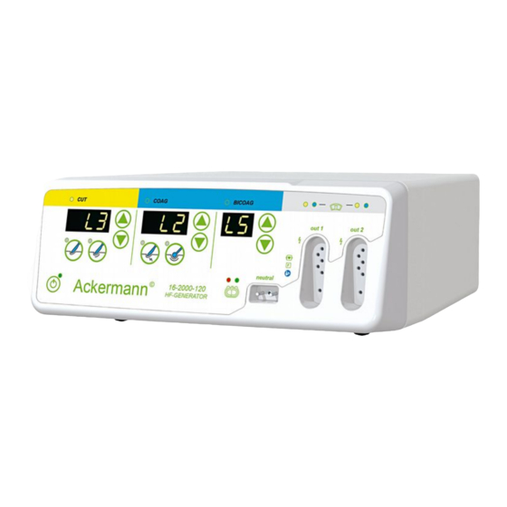
Page 12: Front Panel
USER MANUAL 16-2000-120 Rev. 02/2016 7.1. FRONT PANEL Figure 4. Front view The front panel of the unit contains the following (Fig. 4): standby button neutral electrode monitor NEM neutral electrode socket monopolar electrode socket bipolar electrode socket (K1) pure cutting button... -
Page 13: Back Panel
8. 1. PLACING THE UNIT ON A TROLLEY 16-2000-120 can be placed on a trolley (16-2000-1500). The steel coated trolley is equipped with a movable base with a locking mechanism on the rubber rolls. It has stabilising pins to protect the unit from falling and a case with small shelves for accessories. -
Page 14: Connecting The Power Cable
USER MANUAL 16-2000-120 Rev. 02/2016 8. 2. CONNECTING THE POWER CABLE As the only one, the power cable can be plugged or unplugged only when the unit is off. The unit conforms to class I electric shock protection and requires one phase power supply with sockets equipped with a grounding pin. -
Page 15: Level Settings
USER MANUAL 16-2000-120 Rev. 02/2016 8. 4. LEVEL SETTINGS The unit is equipped with a system for automatic output power adjustment depending on the operating conditions. The processor measures in real time all the operating parameters and adjusts on an ongoing basis the delivered power, current and voltage so as to attain the selected level. -
Page 16: Volume Adjustment
Figure 8. Volume adjustment. 9.3. NEUTRAL ELECTRODE MONITORING In the monopolar operating mode, the unit requires a neutral electrode to be connected . Ackermann units are equipped with a neutral electrode application monitoring system. The NEM system installed in Ackermann HF units is designed for use with Ackermann disposable neutral electrodes with the catalogue number 16-2000-1212DFL. -
Page 17: Disposable Electrodes
Neutral electrodes other than those mentioned above may not ensure proper cooperation with the NEM neutral electrode safety system. The manufacturer is not responsible for the use of Ackermann HF units with neutral electrodes other than those mentioned above, or for any incidents resulting from such use. -
Page 18: Reusable Electrodes
USER MANUAL 16-2000-120 Rev. 02/2016 Check the neutral electrode application and the connected cables every time the patient’s position has been changed. Protect the neutral electrodes against wetting during the procedure. 9.3.2. REUSABLE NEUTRAL ELECTRODES When performing surgical procedures: - requiring high power settings (e.g. TURP);... -
Page 19: Neutral Electrode Application Principles
USER MANUAL 16-2000-120 Rev. 02/2016 9.3.3. NEUTRAL ELECTRODE APPLICATIOM PRINCIPLES Do not apply the electrode on scar tissue, cuts or scratches. Do not apply the electrode in areas which are concave, particularly convex or bony. Do not apply the electrode on excessively hairy skin – if necessary, remove the hair. -
Page 20: Unit Overload Control
USER MANUAL 16-2000-120 Rev. 02/2016 → Correct sites of the neutral electrode application on adult patients. → Correct sites of the neutral electrode application on a child. 9.4. UNIT OVERLOAD CONTROL The unit is equipped with a system limiting its operation time to prevent it from overheating (OVERLOAD). -
Page 21: Monopolar Cutting
USER MANUAL 16-2000-120 Rev. 02/2016 Do not restrict unit cooling during its operation. It means that the unit cannot be covered with anything during its operation. If the unit rests on a shelf, ensure that there is at least 2 [cm] clearance above the unit. -
Page 22: Monopolar Coagulation
USER MANUAL 16-2000-120 Rev. 02/2016 It is possible to set the activation of monopolar cutting by a two-button footswitch using button K11 – it is signalled by a yellow diode situated left of button K11. Monopolar cutting can also be activated using a single-button footswitch. In order to do so, set the footswitch in the monopolar cutting activation mode using button K11 –... -
Page 23: Bipolar Coagulation
USER MANUAL 16-2000-120 Rev. 02/2016 Figure 12. Coagulation level display, coagulation type and level adjustment buttons and monopolar electrode socket In the monopolar coagulation mode, the unit is activated using the blue button in the electrode handle or the blue or grey button of the footswitch. -
Page 24: Switching Off The Unit
USER MANUAL 16-2000-120 Rev. 02/2016 The manner of connecting electrodes is explained in Fig. 7. Figure 13. Bipolar coagulation level display, level adjustment buttons and bipolar electrode socket. Selection of the function activated by a footswitch: cutting / monopolar coagulation / bipolar coagulation (K11). -
Page 25: Protection Measures And Warnings
USER MANUAL 16-2000-120 Rev. 02/2016 10 PROTECTION MEASURES AND WARNINGS 10.1 When performing electrosurgical procedures, minimise the risk of burns by: a) using only the recommended accessories, b) constantly checking the cables for connecting the application electrodes, and in particular the condition of their insulation, c) the correct application of the neutral electrode (see Section 9.3 “Neutral Electrode Monitoring”),... - Page 26 USER MANUAL 16-2000-120 Rev. 02/2016 Examples of locations where the channelling effect may occur: The application site of monopolar high-frequency current Place where the high-frequency current cumulates. Risk of burns 10.7 The output power setting should not be greater than necessary for performing a given procedure.
-
Page 27: Technical Inspection, Warranty And Service
On-site measurements have confirmed that Ackermann generators ensure a high level of electromagnetic safety. Under typical work conditions, an 8-hour daily exposure field occurs at a distance of 5 to 15 [cm] from the working cables. - Page 28 In order to ensure the correct operation of the device, the installation and staff training should be performed by an authorised representative of Ackermann. Each participant of such training receives a certificate which entitles him/her to use Ackermann electrosurgical units. These procedures are obligatory.
- Page 29 USER MANUAL 16-2000-120 Rev. 02/2016 PURE CUT Effect 1 Effect 5 Effect 9 Resistance [Ω] PURE CUT Effect 1 Effect 5 Effect 9 Resistance [Ω] PAGE 29 OF 39...
- Page 30 USER MANUAL 16-2000-120 Rev. 02/2016 MODE BLEND CUT FREQUENCY 333 kHz ±10% MATCHING RESISTANCE 300 Ω WAVEFORM SINE WAVE WITH MODULATION (DUTY CYCLE FROM 40% TO 80%) MAXIMUM REPETITIVE PEAK-TO-PEAK 2100 V VOLTAGE MAXIMUM POWER TRANSFER FOR MATCHING 120 W ±20%...
- Page 31 USER MANUAL 16-2000-120 Rev. 02/2016 MODE FORCED COAG FREQUENCY 333 kHz ±10% MATCHING RESISTANCE 300 Ω WAVEFORM SINE WAVE WITH MODULATION (DUTY CYCLE FROM 25% TO 45%) MAXIMUM REPETITIVE PEAK-TO-PEAK 2100 V VOLTAGE MAXIMUM POWER TRANSFER FOR MATCHING 120 W ±20%...
- Page 32 USER MANUAL 16-2000-120 Rev. 02/2016 MODE SOFT COAG FREQUENCY 333 kHz ±10% MATCHING RESISTANCE 50 Ω WAVEFORM SINE WAVE MAXIMUM REPETITIVE PEAK-TO-PEAK 400 V VOLTAGE MAXIMUM POWER TRANSFER FOR MATCHING 120 W ±20% RESISTANCE SOFT COAG Effect 1 Effect 5 Effect 9 Resistance [Ω]...
- Page 33 USER MANUAL 16-2000-120 Rev. 02/2016 MODE BICOAG FREQUENCY 333 kHz ±10% MATCHING RESISTANCE 50 Ω WAVEFORM SINE WAVE MAXIMUM REPETITIVE PEAK-TO-PEAK 400 V VOLTAGE MAXIMUM POWER TRANSFER FOR MATCHING 120 W ±20% RESISTANCE BICOAG Effect 1 Effect 5 Effect 9 Resistance [Ω]...
-
Page 34: Unit And Accessories Maintenance
12. UNIT AND ACCESSORIES MAINTANCE CLEANING 16-2000-120 has been designed to ensure easier-than-ever operation and maintaining the unit clean, in combination with its versatile applications in electrosurgical procedures. As the unit casing is made of metal without any ventilation holes, it can be cleaned using disinfectants, and the touch panel can be cleaned using alcohol-based disinfectants. -
Page 35: Mechanical Washing
USER MANUAL 16-2000-120 Rev. 02/2016 The following agents are recommended for disinfecting neutral (silicone) electrodes: MANUFACTURER PRODUCT Henkel Hygiene Incidin perfekt Minutil Incidur F 12.1.2. MECHANICAL WASHING MANUFACTURER PRODUCT Henkel Hygiene Sekumatic FR / Washing Sekumatic FRE / Washing Sekumatic FD / Disinfection Schuelke &... -
Page 36: Environmental Requirements
14. ELECTROMAGNETIC EMISSIONS GUIDANCE AND MANUFACTURER'S DECLARATION – ELECTROMAGNETIC EMISSIONS 16-2000-120 is intended for use in the electromagnetic environment specified below. The customer or the user of 16-2000-120 should assure that it is used in such an environment EMISSIONS TEST... - Page 37 USER MANUAL 16-2000-120 Rev. 02/2016 GUIDANCE AND MANUFACTURER'S DECLARATION – ELECTROMAGNETIC IMMUNITY 16-2000-120 is intended for use in the electromagnetic environment specified below. The customer or the user of 16-2000-120 should assure that it is used in such an environment.
- Page 38 If the measured field strength in the location in which the unit is used exceeds the applicable RF compliance level above, 16-2000-120 should be observed to verify normal operation. If abnormal performance is observed, additional measures may be necessary, such as re-orienting or relocating the unit.
-
Page 39: Environmental Protection Guidelines
RECOMMENDED SEPARATION DISTANCES BETWEEN PORTABLE AND MOBILE RF COMMUNICATIONS EQUIPMENT AND 16-2000-120 16-2000-120 is intended for use in an electromagnetic environment in which radiated RF disturbances are controlled. The customer or the user of 16-2000-120 can help prevent electromagnetic interference by...
Need help?
Do you have a question about the 16-2000-120 and is the answer not in the manual?
Questions and answers