Table of Contents
Advertisement
Advertisement
Table of Contents

Subscribe to Our Youtube Channel
Related Manuals for ACKERMANN FUSION INSUFFLATOR


Summary of Contents for ACKERMANN FUSION INSUFFLATOR
- Page 1 USER MANUAL 16-2045 FUSION INSUFFLATOR...
-
Page 2: Table Of Contents
USER MANUAL 16-2045 Rev. 09/2017 Contents Preface ____________________________________________________3 About the device _____________________________________________4 Safety instructions____________________________________________5 Regulatory advice ____________________________________________8 Installing the device___________________________________________9 Operating guidelines _________________________________________10 Special Features ____________________________________________13 Suggested decontamination procedures__________________________17 After-sales service and maintenance____________________________ 17 Troubleshooting ____________________________________________ 18 Technical characteristics______________________________________19 Electromagnetic compatibility__________________________________ 20 Symbols___________________________________________________24 Page 2 of 25... -
Page 3: Preface
USER MANUAL 16-2045 Rev. 09/2017 1 Preface Thank you for the confidence you have demonstrated by purchasing the Ackermann Fusion Insufflator. In order to make the best use of this Fusion device while having all the necessary precautions at your disposal, it is essential for you to become acquainted with this manual. -
Page 4: About The Device
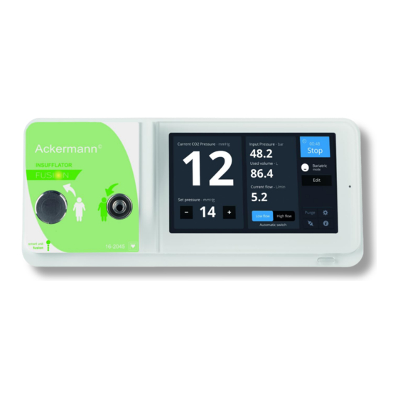
USER MANUAL 16-2045 Rev. 09/2017 2 About the device The Ackermann Fusion insufflator is used for performing surgical or diagnostic endoscopic procedures. It is designed for the purpose of creating and maintaining the pneumoperitoneum (distension of the abdominal cavity with CO2) as part of these procedures. -
Page 5: Safety Instructions
External desufflation valve CO2 outlet – connector for tubings Main power socket Service – to be used by manufacturer only Connection to Ackermann Fusion devices CO2 input – medical grade CO2 bottle or wall plug Equipotenional plug Touch screen – 7“... - Page 6 USER MANUAL 16-2045 Rev. 09/2017 • Unplug the device from the main power if you do not intend to use it for several days or more • Use only the disinfectant methods recommended in section 8 • Prior to each use, make sure that the device does not have any rough surfaces, sharp edges or protruding parts that could cause safety problems •...
- Page 7 USER MANUAL 16-2045 Rev. 09/2017 WARNINGS • Metabolic acidosis and resulting cardiac irregularity Avoid prolonged intra-abdominal pressures above 20 mm of mercury. • Reduction of respiration with compromised diaphragmatic movement • Reduction of venous return • Reduction of cardiac output •...
-
Page 8: Regulatory Advice
4 Regulatory advice 4.1 Compliance This device is designed and manufactured by a Ackermann proven to have a certified quality system. It meets the requirements of European directive 93/42/CEE, on medical devices. Consequently, it particularly meets the standards of electrical safety (IEC) and electromagnetic compatibility (EMC) ad hoc. -
Page 9: Installing The Device
USER MANUAL 16-2045 Rev. 09/2017 symbol displayed on the device and on the accompanying documentation indicates that this product cannot under any circumstances be treated as household waste. It must therefore be delivered to a waste collection center for the recycling of electrical and electronic equipment. -
Page 10: Operating Guidelines
6.1 Activation Turn the switch [S2] to position “1”; the device is now in standby mode (the indicator light on the Standby button [S1] will be flashing, and the Ackermann logo should appear on the touch screen [L1]); Press the Standby button [S1] or tap the touch screen to start the device (the indicator light comes on and the calibration phase, which lasts for a few seconds, starts). - Page 11 USER MANUAL 16-2045 Rev. 09/2017 6.2 Fitting the tubing hose The manufacturer cannot be deemed responsible for reactions or malfunctions associated with the use of damaged or inappropriate tubing hoses. Do not use the tubing hose if its packaging is damaged. Sterile tubing hoses are disposable;...
- Page 12 USER MANUAL 16-2045 Rev. 09/2017 6.4 Activating / Switching-off insufflation Press the “RUN” button on the interface menu to start insufflation. A chronometer is displayed on the screen when insufflation is in progress. The MENU is not accessible when insufflation is in progress.
-
Page 13: Special Features
RUN (in low flow mode), HIGH FLOW RATE, STOP. A special communication cable must connect the Ackermann Fusion camera to this insufflator at the dedicated socket [C5] (see Ackermann Fusion camera user manual for further information on configuring this switch). In addition, this communication cable is for receiving feedback information (instantaneous pressure in the cavity, warning messages) on the surgical monitor. - Page 14 USER MANUAL 16-2045 Rev. 09/2017 7.3 Safety • Preheating system This warms the gas in the device. • Automatic test Automatic calibration of the device and testing of the basic components on each start-up, in less than one second. • Detection of tubing hoses The device will only start if a tubing hose is connected both to the CO2 outlet and the external desufflation valve (for safety reasons, it is impossible to connect only one of these elements).
- Page 15 USER MANUAL 16-2045 Rev. 09/2017 7.5 High flow rate When the pneumoperitoneum is created, activating this mode enables a maximum flow rate of up to 45 L/min to be reached. This capacity is then used to compensate for all types of leakage.
- Page 16 USER MANUAL 16-2045 Rev. 09/2017 7.10 Touch screen [L1] For better communication and for easier use, we have equipped our latest generation of insufflators with a user-friendly touch screen. This serves to provide the following information: • warnings and error messages •...
-
Page 17: Suggested Decontamination Procedures
USER MANUAL 16-2045 Rev. 09/2017 8 Suggested decontamination procedures The insufflator is a medical device, not heat resistant and it cannot withstand immersion; consequently it should be disinfected with a non-woven medium saturated disinfectant detergent. Decontamination methods and/or selected tools, it remains under the full responsibility of the staff concerned. -
Page 18: Troubleshooting
USER MANUAL 16-2045 Rev. 09/2017 10 Troubleshooting Warning Possible Cause Measures to take Change the cylinder. it is advisable to prepare a Cylinder pressure at 40 bars replacement cylinder as soon as the cylinder pressure reaches 40 bars. Orange cylinder logo gas cylinder valve closed Open the valve Turn off the device, check that... -
Page 19: Technical Characteristics
USER MANUAL 16-2045 Rev. 09/2017 Note: If the insufflator does not switch on, this could be due to damage to the fuses. If so, it is advisable to turn off the power, check and if necessary replace the fuses (use only T25AL – 250 V delayed-action UR fuses) For any other problems, contact your nearest after-sales service department. -
Page 20: Electromagnetic Compatibility
USER MANUAL 16-2045 Rev. 09/2017 Standards: • Electrical protection: class 1, type CF • Compliant with standard IEC 60 601-1; with variants for the United States and Canada • No protection against water (IPXO) • Not suitable for use in the presence of a flammable anaesthetic mixture, air, oxygen or nitrous oxide 12 Electromagnetic compatibility 12-1 Manufacturer’s guide and declaration –... - Page 21 USER MANUAL 16-2045 Rev. 09/2017 12-2 Manufacturer’s guide and declaration – electromagnetic immunity This insufflator was designed to be used in the electromagnetic environment specified below. The user must ensure that it is in fact used in this environment. safety test IEC 60601 Compliance electromagnetic environment - guide...
- Page 22 USER MANUAL 16-2045 Rev. 09/2017 12-3 Manufacturer’s guide and declaration – electromagnetic safety This insufflator was designed to be used in the electromagnetic environment specified below. The user must ensure that it is in fact used in this environment. Safety test Compliance electromagnetic environment - guide 60601...
- Page 23 USER MANUAL 16-2045 Rev. 09/2017 a The field strength of fixed transmitters, like base stations for radio telephones (mobile and fixed line) and mobile land radio systems, amateur radio systems, AM/FM radio communication systems and TV systems cannot in theory be evaluated with accuracy. To analyse the electromagnetic environment due to fixed RF transmitters, on site measurements must be taken.
-
Page 24: Symbols
USER MANUAL 16-2045 Rev. 09/2017 13 Symbols Button Indicator light Socket Label Manufacture date Manufacturer Class I product Conforming to European directive 93/42/EEC An equipotential earth socket conductor other than a protective earth or a neutral conductor, allowing direct connection between the electrical equipment and the equalizing bar of the installation potential. - Page 25 USER MANUAL 16-2045 Rev. 09/2017 Page 25 of 25...
Need help?
Do you have a question about the FUSION INSUFFLATOR and is the answer not in the manual?
Questions and answers