
Related Manuals for MSI 845G Max


Summary of Contents for MSI 845G Max
- Page 1 845G Max 845G Max-L MICRO-STAR INTERNATIONAL MS-6580 (v1.X) ATX Mainboard Version 1.0 G52-MA00593...
- Page 2 Manual Rev: 1.0 Release Date: Apr. 2002 FCC-B Radio Frequency Interference Statement This equipment has been tested and found to comply with the limits for a class B digital device, pursuant to part 15 of the FCC rules. These limits are designed to provide reasonable protection against harmful interference when the equip- ment is operated in a commercial environment.
- Page 3 Edition Apr. 2002 Copyright Notice The material in this document is the intellectual property of MICRO-STAR INTERNATIONAL. We take every care in the preparation of this document, but no guarantee is given as to the correctness of its contents. Our products are under continual improvement and we reserve the right to make changes without notice.
- Page 4 Safety Instructions Always read the safety instructions carefully. Keep this User’s Manual for future reference. Keep this equipment away from humidity. Lay this equipment on a reliable flat surface before setting it up. The openings on the enclosure are for air convection hence protects the equipment from overheating.
-
Page 5: Table Of Contents
Mouse Connector ................. 2-8 Keyboard Connector ..............2-9 USB Connectors ................2-9 Serial Port Connectors: COM A & COM B ........2-10 VGA DB 15-Pin Connector ............2-10 Parallel Port Connector: LPT1 ............2-11 LAN (RJ-45) Jack (845G Max-L only) ........... 2-12... - Page 6 Joystick/Midi Connector ............. 2-12 Audio Port Connectors ............... 2-12 Connectors ..................2-13 Floppy Disk Drive Connector: FDD1 ........... 2-13 Hard Disk Connectors: IDE1 & IDE2 ........... 2-14 Fan Power Connectors: CPUFAN1/SYS_FAN1/PWR_FAN1 ..2-15 IrDA Infrared Module Header: IR1 ..........2-16 Bluetooth Connector: JBT1 ............
- Page 7 Power Management Features ............. 3-16 PNP/PCI Configurations ..............3-20 Integrated Peripherals ................ 3-23 PC Health Status ................3-26 Frequency/Voltage Control ..............3-27 Set Supervisor/User Password ............3-29 Load High Performance/BIOS Setup Defaults ........3-30 Glossary ....................G-1...
-
Page 8: Chapter 1. Getting Started
There are two models available for 845G Max series mainboards: 845G Max and 845G Max-L. 845G Max does not support the LAN function while 845G Max-L is implemented with the LAN function and offers an onboard LAN RJ-45 jack. -
Page 9: Mainboard Specification
Chapter 1 Mainboard Specification Supports Socket 478 for Intel Pentium 4 processor ® Supports 1.3GHz, 1.4GHz, 1.5GHz, 1.6GHz, 1.7GHz, 1.8GHz, 1.9GHz, 2GHz, 2. 1GHz, 2.2GHz, 2.26GHz, 2.4GHz and up Chipset Intel® 845G chipset (788 FC-BGA) - AGP 4x slot (1.5V only) - Integrated graphic controller - Supports 100/133MHz FSB - Supports 400/533MHz Intel NetBurst micro-architecture bus... - Page 10 Getting Started - 6 USB 2.0/1.1 ports (Rear * 2 / Front * 4) - 1 Line-In/Line-Out/Mic-In/Game port - 1 RJ45 connector (optional) Network (845G Max-L only) ICH4 Integrated LAN controller Intel 82562ET - ACPI and APM supported - Wake-On-LAN and WFM 2.0 supported...
-
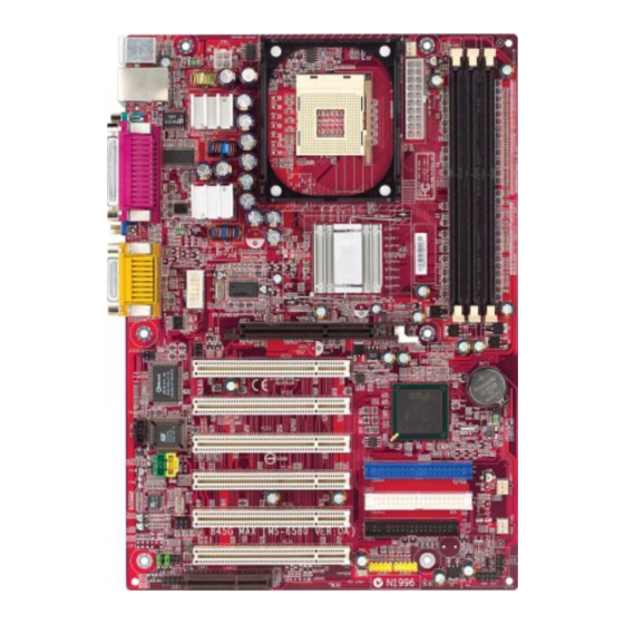
Page 11: Mainboard Layout
PCI Slot 2 ICH 4 PCI Slot 3 JBAT1 JGS1 IDE 1 PCI Slot 4 SYS_FAN1 IDE 2 PCI Slot 5 Codec PWR_FAN1 JBT1 FDD1 PCI Slot 6 JAUDIO1 JFP2 JUSB1 JUSB2 JDB1 JFP1 845G Max (MS-6580 v1.X) ATX Mainboard... - Page 12 PCI Slot 2 ICH 4 PCI Slot 3 JBAT1 JGS1 IDE 1 PCI Slot 4 SYS_FAN1 IDE 2 PCI Slot 5 Codec PWR_FAN1 JBT1 FDD1 PCI Slot 6 JAUDIO1 JFP2 JUSB1 JUSB2 JDB1 JFP1 845G Max-L (MS-6580 v1.X) ATX Mainboard...
-
Page 13: Quick Components Guide
Chapter 1 Quick Components Guide Component Function Reference DDR1~3 Installing DDR SDRAM modules See p. 2-5~2-6 Socket 478 Installing CPU See p. 2-2~2-3 CPUFAN1 Connecting to CPUFAN See p. 2-15 SYS_FAN1 Connecting to SYSTEM FAN See p. 2-15 PWR_FAN1 Connecting to POWER SUPPLY FAN See p. -
Page 14: Msi Special Features
After rebooting, click Turbo to apply the test result. Click Default to restore the default values. Features: MSI Logo links to the MSI Web site CPU Speed allows users to adjust the CPU speed through CPU Multiplier and FSB... -
Page 15: Live Bios™/Live Driver
Web site. To use the function, you need to install the “MSI Live Update Series 2” application. After the installation, the “MSI Live Update Series 2” icon (as shown on the right) will appear on the screen. Double click the “MSI Live Update Series 2” icon, and the following screen will appear: Five buttons are placed on the leftmost pane of the screen. -
Page 16: Live Monitor
Live Monitor™ The Live Monitor™ is a tool used to schedule the search for the latest BIOS/drivers version on the MSI Web site. To use the function, you need to install the “MSI Live Update Series 2” application. After the installation, the “MSI Live Monitor” icon (as shown on the right) will appear on the screen. -
Page 17: D-Bracket™ 2 (Optional)
Chapter 1 D-Bracket™ 2 (Optional) D-Bracket™ 2 is a USB bracket integrating four Diagnostic LEDs, which use graphic signal display to help users understand their system. The LEDs provide up to 16 combinations of signals to debug the system. The 4 LEDs can detect all problems that fail the system, such as VGA, RAM or other failures. - Page 18 Getting Started D-Bracket™ 2 Description Processor Initialization - This will show information regarding the processor (like brand name, system bus, etc…) Testing RTC (Real Time Clock) Initializing Video Interface - This will start detecting CPU clock, checking type of video onboard.
-
Page 19: Chapter 2. Hardware Setup
Hardware Setup Chapter 2. Hardware Setup Hardware Setup This chapter provides you with the information about hardware setup procedures. While doing the installation, be careful in holding the compo- nents and follow the installation procedures. For some components, if you install in the wrong orientation, the components will not work properly. -
Page 20: Central Processing Unit: Cpu
Chapter 2 Central Processing Unit: CPU ® ® The mainboard supports Intel Pentium 4 processor in the 478 pin package. The mainboard uses a CPU socket called PGA478 for easy CPU installation. When you are installing the CPU, make sure the CPU has a heat sink and a cooling fan attached on the top to prevent overheating. -
Page 21: Installing The Cpu Fan
Hardware Setup Installing the CPU Fan As processor technology pushes to faster speeds and higher performance, thermal management becomes increasingly important. To dissi- pate heat, you need to attach the CPU cooling fan and heatsink on top of the CPU. Follow the instructions below to install the Heatsink/Fan: Locate the CPU and its retention Position the heatsink onto the reten- mechanism on the motherboard. -
Page 22: Cpu Core Speed Derivation Procedure
Chapter 2 Connect the fan power cable from the mounted fan to the 3-pin fan power connector on the board. fan power cable CPU Core Speed Derivation Procedure CPU Clock 100MHz Core/Bus ratio then CPU core speed Host Clock x Core/Bus ratio 100MHz x 14 1.4GHz Overclocking... -
Page 23: Memory
Hardware Setup Memory The mainboard provides 3 sockets for 184-pin DDR SDRAM DIMM (Double In-Line Memory Module) modules and supports the memory size up to 2GB. You can install PC2100/DDR266 or PC1600/DDR200 DRAM modules on the DDR DIMM slots (DIMM 1~3). DDR DIMM Slots (DIMM 1~3) Introduction to DDR SDRAM... -
Page 24: Dimm Module Combination
Chapter 2 DIMM Module Combination Install at least one DIMM module on the slots. You can install either single- or double-sided modules to meet your own needs. ® Intel 82845G chipset supports a maximum of 4 memory banks. DIMM 1 alone occupies two memory banks;... -
Page 25: Power Supply
Hardware Setup Power Supply The mainboard supports ATX power supply for the power system. Be- fore inserting the power supply connector, always make sure that all compo- nents are installed properly to ensure that no damage will be caused. ATX 20-Pin Power Connector: PWR1 This connector allows you to connect to an ATX power supply. -
Page 26: Back Panel
Chapter 2 Back Panel The Back Panel provides the following connectors: Parallel Midi/Joystick (Optional) Mouse Keyboard USB COM A L-out L-in MIC Mouse Connector ® The mainboard provides a standard PS/2 mouse mini DIN connector for ® ® attaching a PS/2 mouse. -
Page 27: Keyboard Connector
Hardware Setup Keyboard Connector ® The mainboard provides a standard PS/2 keyboard mini DIN connector ® ® for attaching a PS/2 keyboard. You can plug a PS/2 keyboard directly into this connector. Pin Definition SIGNAL DESCRIPTION Keyboard DATA Keyboard DATA No connection Ground Keyboard Clock... -
Page 28: Serial Port Connectors: Com A & Com B
Chapter 2 Serial Port Connectors: COM A & COM B The mainboard offers two 9-pin male DIN connectors as serial port COM A & COM B (COM B is the header COM2 on the board). The ports are 16550A high speed communication ports that send/receive 16 bytes FIFOs. You can attach a serial mouse or other serial devices directly to the connectors. -
Page 29: Parallel Port Connector: Lpt1
Hardware Setup Parallel Port Connector: LPT1 The mainboard provides a 25-pin female centronic connector as LPT. A parallel port is a standard printer port that supports Enhanced Parallel Port (EPP) and Extended Capabilities Parallel Port (ECP) mode. Pin Definition SIGNAL DESCRIPTION STROBE Strobe... -
Page 30: Lan (Rj-45) Jack (845G Max-L Only)
Chapter 2 LAN (RJ-45) Jack (845G Max-L only) The mainboard optionally provides one standard RJ-45 jack for connec- tion to Local Area Network (LAN). You can connect a network cable to the LAN jack. Pin Definition SIGNAL DESCRIPTION Transmit Differential Pair... -
Page 31: Connectors
Hardware Setup Connectors The mainboard provides connectors to connect to FDD, IDE HDD, case, USB Ports, IR module, bluetooth module, D-Bracket™ and CPU/System/Power Supply FAN. Floppy Disk Drive Connector: FDD1 The mainboard provides a standard floppy disk drive connector that supports 360K, 720K, 1.2M, 1.44M and 2.88M floppy disk types. -
Page 32: Hard Disk Connectors: Ide1 & Ide2
Chapter 2 Hard Disk Connectors: IDE1 & IDE2 The mainboard has a 32-bit Enhanced PCI IDE and Ultra DMA 66/100 controller that provides PIO mode 0~5, Bus Master, and Ultra DMA 66/100 function. You can connect up to four hard disk drives, CD-ROM, 120MB Floppy (reserved for future BIOS) and other devices. -
Page 33: Fan Power Connectors: Cpufan1/Sys_Fan1/Pwr_Fan1
Hardware Setup Fan Power Connectors: CPUFAN1/SYS_FAN1/PWR_FAN1 The CPUFAN1 (processor fan), SYS_FAN1 (system fan) and PWR_FAN1 (power supply fan) support system cooling fan with +12V. It supports three- pin head connector. When connecting the wire to the connectors, always take note that the red wire is the positive and should be connected to the +12V, the black wire is Ground and should be connected to GND. -
Page 34: Irda Infrared Module Header: Ir1
Chapter 2 IrDA Infrared Module Header: IR1 The connector allows you to connect to IrDA Infrared module. You must configure the setting through the BIOS setup to use the IR function. IR1 is ® compliant with Intel Front Panel I/O Connectivity Design Guide. IR1 Pin Definition Signal VCC5... -
Page 35: Front Panel Connectors: Jfp1 & Jfp2
Hardware Setup Front Panel Connectors: JFP1 & JFP2 The mainboard provides two front panel connectors for electrical con- ® nection to the front panel switches and LEDs. JFP1 is compliant with Intel Front Panel I/O Connectivity Design Guide. Speaker Power JFP2 Reset Switch... -
Page 36: Front Panel Audio Connector: Jaudio1
Chapter 2 Front Panel Audio Connector: JAUDIO1 The JAUDIO1 front panel audio connector allows you to connect to the ® front panel audio and is compliant with Intel Front Panel I/O Connectivity Design Guide. JAUDIO1 Pin Definition SIGNAL DESCRIPTION AUD_MIC Front panel microphone input signal AUD_GND Ground used by analog audio circuits... -
Page 37: Front Usb Connectors: Jusb1/2
Hardware Setup Front USB Connectors: JUSB1/2 The mainboard provides two USB2.0 pinheaders for users to connect to ® optional USB2.0 ports. These pinheaders are compliant to Intel I/O Connec- tivity Design Guide. USB 2.0 technology increases data transfer rate up to a maximum through- put of 480Mbps, which is 40 times faster than USB 1.1, and is ideal for connect- ing high-speed USB interface peripherals such as USB HDD, digital cameras, MP3 players, printers, modems and the like. - Page 38 Chapter 2 To Attach the Optional USB 2.0 Ports: 1. Take out the USB 2.0 bracket and D-Bracket™ 2 (if there is any). 2. Locate the blue USB pinheader (JUSB2) and yellow USB pinheader (JUSB1) on the motherboard. 3. Connect the USB 2.0 bracket to blue USB pinheader, and D-Bracket™ 2 to yellow USB pinheader.
-
Page 39: Cd-In Connector: Cd_In1
Hardware Setup CD-In Connector: CD_IN1 The connector is for CD-ROM audio connector. CD_IN1 2-21... -
Page 40: D-Bracket™ 2 Connector: Jdb1
Chapter 2 D-Bracket™ 2 Connector: JDB1 The mainboard comes with a JDB1 connector for you to connect to D- Bracket™ 2. D-Bracket™ 2 is a USB Bracket that supports both USB1.1 & 2.0 spec. It integrates four LEDs and allows users to identify system problem through 16 various combinations of LED signals. -
Page 41: Chassis Intrusion Switch Connector: Jcase1
Hardware Setup Chassis Intrusion Switch Connector: JCASE1 This connector is connected to a 2-pin chassis switch. If the chassis is opened, the switch will be short. The system will record this status and show a warning message on the screen. To clear the warning, you must enter the BIOS utility and clear the record. -
Page 42: Jumpers
Chapter 2 Jumpers The motherboard provides one jumper for you to set the computer’s function. This section will explain how to change your motherboard’s function through the use of the jumper. Clear CMOS Jumper: JBAT1 There is a CMOS RAM on board that has a power supply from external battery to keep the data of system configuration. -
Page 43: Slots
3V AGP card may cause damages to the mainboard. To avoid the risk of causing permanent damages to the mainboard, the AGP slot is protected with MSI electrical routing device. If users have inserted a 3.3V AGP card into the slot, the MSI routing device will disable the computer’s boot-up system. Re- move the 3.3V AGP card and the boot-up system will return to normal. -
Page 44: Pci Slots
Its main processing is done through software and controlled by the motherboard’s chipset. Please note the CNR slot of 845G Max-L supports audio and modem only, so you cannot install a LAN card on the CNR slot. Only the CNR slot of 845G Max supports network, audio and modem. -
Page 45: Pci Interrupt Request Routing
Hardware Setup PCI Interrupt Request Routing The IRQ, abbreviation of interrupt request line and pronounced I-R-Q, are hardware lines over which devices can send interrupt signals to the microprocessor. The “AGP/PCI/USB/LAN” IRQ pins are typically connected to the PCI bus INT A# ~ INT H# pins as follows: Order 1 Order 2 Order 3 Order 4 INT A# INT B#... -
Page 46: Chapter 3. Bios Setup
BIOS Setup Chapter 3. BIOS Setup BIOS Setup This chapter provides information on the BIOS Setup program and allows you to configure the system for optimum use. You may need to run the Setup program when: An error message appears on the screen during the system booting up, and requests you to run SETUP. -
Page 47: Entering Setup
Chapter 3 Entering Setup Power on the computer and the system will start POST (Power On Self Test) process. When the message below appears on the screen, press <DEL> key to enter Setup. DEL:Setup F12:Network boot TAB:Logo If the message disappears before you respond and you still wish to enter Setup, restart the system by turning it OFF and On or pressing the RESET button. -
Page 48: Getting Help
BIOS Setup Getting Help After entering the Setup utility, the first screen you see is the Main Menu. Main Menu The main menu displays the setup categories the BIOS supplies. You can use the arrow keys ( ↑↓ ) to select the item. The on-line description for the selected setup category is displayed at the bottom of the screen. -
Page 49: The Main Menu
Chapter 3 The Main Menu Once you enter AMIBIOS NEW SETUP UTILITY, the Main Menu will appear on the screen. The Main Menu displays twelve configurable functions and two exit choices. Use arrow keys to move among the items and press <Enter> to enter the sub-menu. - Page 50 BIOS Setup Integrated Peripherals Use this menu to specify your settings for integrated peripherals. PC Health Status This entry shows your PC health status. Frequency/Voltage Control Use this menu to specify your settings for frequency/voltage control. Set Supervisor Password Use this menu to set Supervisor Password. Set User Password Use this menu to set User Password.
-
Page 51: Standard Cmos Features
Chapter 3 Standard CMOS Features The items inside STANDARD CMOS FEATURES menu are divided into 9 categories. Each category includes none, one or more setup items. Use the arrow keys to highlight the item you want to modify and use the <PgUp> or <PgDn>... - Page 52 BIOS Setup Primary/Secondary IDE Master/Slave Press <Enter> to enter the sub-menu screen. When you select a specific hard disk drive type, the specification of hard disk drive will show up on the screen according to your selection. Type: Press PgUp/<+> or PgDn/<-> to select the type of the device. Cylinders: Select the number of cylinders.
-
Page 53: Advanced Bios Features
Chapter 3 Advanced BIOS Features Quick Boot Setting the item to Enabled allows the system to boot within 5 seconds since it will skip some check items. Available options: Enabled, Disabled. Full Screen LOGO Show This item enables you to show the company logo on the bootup screen. Set- tings are: Silent Shows a still image (logo) on the full screen at boot. - Page 54 BIOS Setup 1st/2nd/3rd The items allow you to set the sequence of boot devices where AMIBIOS attempts to load the operating system. The settings are: IDE-0 The system will boot from the first HDD. IDE-1 The system will boot from the second HDD. IDE-2 The system will boot from the third HDD.
- Page 55 Chapter 3 Note: Available settings for “1st/2nd/3rd” boot device vary depend- ing on the bootable devices you have installed. For example, if you did not install a floppy drive, the setting “Floppy” does not show up. Try Other Boot Devices Setting the option to Yes allows the system to try to boot from other devices if the system fails to boot from the 1st/2nd/3rd boot device.
- Page 56 BIOS Setup Boot OS/2 for DRAM > 64MB ® This allows you to run the OS/2 operating system with DRAM larger than ® 64MB. When you choose No, you cannot run the OS/2 operating system with DRAM larger than 64MB. But it is possible if you choose Yes. APIC Interrupt Mode This field is used to enable or disable the APIC (Advanced Programmable Interrupt Controller).
- Page 57 Chapter 3 memory area, a system error may result. Setting options: Enabled, Disabled. C000, 32k Shadow This item specifies how the contents of the adapter ROM named in the item are handled. Settings are described below: Option Description Disabled The specified ROM is not copied to RAM. Enabled The contents of specified ROM are copied to RAM for faster system performance.
-
Page 58: Advanced Chipset Features
BIOS Setup Advanced Chipset Features Note: Change these settings only if you are familiar with the chipset. DRAM Timing Setting Press <Enter> and the following sub-menu appears. DRAM Frequency Use this item to configure the clock frequency of the installed SDRAM. Settings options: Auto, 200MHz, 266MHz, 333MHz. - Page 59 Chapter 3 Configure DRAM Timing by SPD Selects whether DRAM timing is controlled by the SPD (Serial Presence Detect) EEPROM on the DRAM module. Setting to Enabled enables CAS# Latency, RAS# Precharge, RAS# to CAS# Delay, Precharge Delay and Burst Length automatically to be determined by BIOS based on the configurations on the SPD.
- Page 60 BIOS Setup the next memory location. The bigger the size, the faster the DRAM performance. Settings: 4, 8 (QW). AGP Aperture Size This setting controls just how much system RAM can be allocated to AGP for video purposes. The aperture is a portion of the PCI memory address range dedicated to graphics memory address space.
-
Page 61: Power Management Features
Chapter 3 Power Management Features IPCA Function This item is to activate the ACPI (Advanced Configuration and Power Man- agement Interface) function. If your operating system is ACPI-aware, such as Windows 98SE/2000/ME, select Yes. Available options: Yes, No. ACPI Standby State This item specifies the power saving modes for ACPI function. - Page 62 BIOS Setup Re-Call VGA BIOS at S3 Resuming Selecting Enabled allows BIOS to call VGA BIOS to initialize the VGA card when system wakes up (resume) from S3 sleep state. The system resume time is shortened when you disable the function, but system will need an AGP driver to initialize the VGA card.
- Page 63 Chapter 3 FDC/LPT/COM Ports, Primary/Secondary Master/Slave IDE These fields specify whether the system will be awakened from power saving modes when activity or input signal of the specified hardware peripheral or component is detected. Set Wake Up Events Press <Enter> to enter the sub-menu and the following screen appears: Keyboard/Mouse PowerOn Function, Specific Key for PowerOn, Resume On Ring/PME#, USB Wakeup From S3 These fields specify whether the system will be awakened from power...
- Page 64 BIOS Setup peripheral or component is detected. Note: 1. You need to install a modem card supporting power on function for “Resume On Ring” function. 2. For “Keyboard PowerOn Function”, the option “Specific Key” refers to the password you specify in the “Specific Key for PowerOn” field.
-
Page 65: Pnp/Pci Configurations
Chapter 3 PNP/PCI Configurations This section describes configuring the PCI bus system and PnP (Plug & Play) feature. PCI, or Peripheral Component Interconnect, is a system which allows I/O devices to operate at speeds nearing the speed the CPU itself uses when communicating with its special components. - Page 66 BIOS Setup tings are: Internal VGA The system initializes the onboard VGA device. AGP/Int-VGA The system initializes the installed AGP card first. If an AGP card is not available, it will initialize the onboard VGA device. AGP/PCI The system initializes the installed AGP card first. If an AGP card is not available, it will initialize the PCI VGA card.
- Page 67 Chapter 3 IRQ 3/4/5/7/9/10/11/14/15 These items specify the bus where the specified IRQ line is used. The settings determine if AMIBIOS should remove an IRQ from the pool of available IRQs passed to devices that are configurable by the system BIOS.
-
Page 68: Integrated Peripherals
BIOS Setup Integrated Peripherals USB Controller This setting is used to enable/disable the onboard USB controllers. Setting options: 2 USB Ports, 4 USB Ports, 6 USB Ports, Disabled. USB 1.1 Legacy Support Set to All Device if you need to use a USB1.1 device in the operating system that does not support or have any USB driver installed, such as DOS and SCO Unix. - Page 69 Chapter 3 audio device is detected, the onboard AC’97 (Audio Codec’97) controller will be enabled; if not, it is disabled. Disable the controller if you want to use other controller cards to connect an audio device. Settings: Auto, Disabled. AC’97 Modem Auto allows the mainboard to detect whether a modem is used.
- Page 70 BIOS Setup Auto, 3F8/COM1, 2F8/COM2, 3E8/COM3, 2E8/COM4, Disabled. Serial Port B Mode This item sets the operation mode for Serial Port B. Settings: Normal, 1.6 uS, 3/16 Baud and ASKIR (the last three operation modes are setting options for IR function). IR Pin Select Set to IRRX/IRTX when using an internal IR module connected to the IR header.
-
Page 71: Pc Health Status
Chapter 3 PC Health Status This section shows the status of your CPU, fan, and overall system status. Chassis Intrusion The field enables or disables the feature of recording the chassis intrusion status and issuing a warning message if the chassis is once opened. To clear the warning message, set the field to Reset. -
Page 72: Frequency/Voltage Control
BIOS Setup Frequency/Voltage Control Use this menu to specify your settings for frequency/voltage control. Spread Spectrum When the motherboard clock generator pulses, the extreme values (spikes) of the pulses creates EMI (Electromagnetic Interference). The Spread Spectrum function reduces the EMI generated by modulating the pulses so that the spikes of the pulses are reduced to flatter curves. - Page 73 Chapter 3 frequency; otherwise, the CPU will run at the default configuration 100MHz. The field also allows you to overclock the processor by adjusting the FSB clock to a higher frequency. CPU Vcore Adjust This setting is used to enable or disable the ability to adjust CPU Vcore for overclocking purpose.
-
Page 74: Set Supervisor/User Password
BIOS Setup Set Supervisor/User Password When you select this function, a message as below will appear on the screen: Type the password, up to six characters in length, and press <Enter>. The password typed now will replace any previously set password from CMOS memory. -
Page 75: Load High Performance/Bios Setup Defaults
Chapter 3 Load High Performance/BIOS Setup Defaults The two options on the main menu allow users to restore all of the BIOS settings to High Performance defaults or BIOS Setup defaults. The High Per- formance Defaults are the default values set by the mainboard manufacturer for the best system performance but probably will cause a stability issue. -
Page 76: Glossary
Glossary Glossary Glossary ACPI (Advanced Configuration & Power Interface) This power management specification enables the OS (operating system) to control the amount of power given to each device attached to the computer. Windows 98/98SE, Windows 2000 and Windows ME can fully support ACPI to allow users managing the system power flexibly. - Page 77 Glossary example, a modem chipset contains all the primary circuits for transmitting and receiv- ing data; a PC chipset provides the electronic interfaces between all subsystems. CMOS (complementary metal-oxide semiconductor) CMOS is a widely used type of semiconductor, which features high speed and low power consumption.
- Page 78 Glossary ECC Memory (error correcting code memory) A type of memory that contains special circuitry for testing the accuracy of data and correcting the errors on the fly. IDE (Integrated Drive Electronics) A type of disk-drive interface widely used to connect hard disks, CD-ROMs and tape drives to a PC, in which the controller electronics is integrated into the drive itself, eliminating the need for a separate adapter card.
- Page 79 Glossary PCI (Peripheral Component Interconnect) A local bus standard developed by Intel that first appeared on PCs in late 1993. PCI provides “plug and play” capability and allows IRQs to be shared. The PCI controller can exchange data with the system's CPU either 32 bits or 64 bits at a time. PnP (Plug and Play) A set of specifications that allows a PC to configure itself automatically to work with peripherals.
Need help?
Do you have a question about the 845G Max and is the answer not in the manual?
Questions and answers