
Related Manuals for MSI 845 Ultra


Summary of Contents for MSI 845 Ultra
- Page 1 845 Ultra 845 Ultra-AR 845 Ultra-ARU MICRO-STAR INTERNATIONAL MS-6398 (v1.X) ATX Mainboard Version 1.1 G52-MA00512...
- Page 2 Manual Rev: 1.1 Release Date: Nov. 2001 FCC-B Radio Frequency Interference Statement This equipment has been tested and found to comply with the limits for a class B digital device, pursuant to part 15 of the FCC rules. These limits are designed to provide reasonable protection against harmful interference when the equip- ment is operated in a commercial environment.
- Page 3 Edition Nov. 2001 Copyright Notice The material in this document is the intellectual property of MICRO-STAR INTERNATIONAL. We take every care in the preparation of this document, but no guarantee is given as to the correctness of its contents. Our products are under continual improvement and we reserve the right to make changes without notice.
- Page 4 Safety Instructions Always read the safety instructions carefully. Keep this User’s Manual for future reference. Keep this equipment away from humidity. Lay this equipment on a reliable flat surface before setting it up. The openings on the enclosure are for air convection hence protects the equipment from overheating.
-
Page 5: Table Of Contents
Mainboard Specification ..............1-2 Mainboard Layout ................1-4 Quick Components Guide ..............1-7 Key Features ..................1-8 MSI Special Features ................1-9 Fuzzy Logic™ III ................1-9 PC Alert™ III ................1-10 D-Bracket™ ................. 1-12 Live BIOS™/Live Driver™ ............1-14 Chapter 2. - Page 6 Audio Port Connectors ............... 2-10 Parallel Port Connector: LPT1 ............2-11 Connectors ..................2-12 Floppy Disk Drive Connector: FDD1 ........... 2-12 IrDA Infrared Module Header: IR2 ..........2-12 Hard Disk Connectors: IDE1 & IDE2 ........... 2-13 ATA133 RAID Connectors: IDE3 & IDE4 ........2-14 CD-In Connector: JCD1 ...............
- Page 7 Appendix A: Using 4-/6-channel Audio Function ........A-1 Installing C-Media Drivers ..............A-2 Hardware Configuration ..............A-2 Software Configuration ............... A-3 Appendix B: MSI Smart Key ..............B-1 Installing MSI Smart Key ..............B-2 Using MSI Smart Key ................. B-3 Glossary ....................G-1...
-
Page 8: Chapter 1. Getting Started
Thank you for purchasing the MS-6398 v1.X ATX mainboard. The MS- 6398 v1.X series include 845 Ultra, 845 Ultra-AR, and 845 Ultra-ARU mainboards. The 845 Ultra is a standard version. In addition to standard features, the 845 Ultra-AR offers ATA133 RAID interface and the 845 Ultra-ARU supports ATA133 RAID and USB 2.0 technology. -
Page 9: Mainboard Specification
Chapter 1 Mainboard Specification Supports Intel Pentium 4 processor in 478 pin package. ® ® Supports 1.5GHz, 1.6GHz, 1.7GHz, 1.8GHz, 1.9GHz, 2GHz, 2.1GHz, 2.2GHz and up. Chipset Intel 845 chipset (593 FC-BGA) ® - Supports DDR SDRAM at 200/266MHz operation (DDR200/DDR266). - AGTL+ host bus with integrated termination supporting 32-bit host addressing. - Page 10 An IDE controller on the ICH2 chipset provides IDE HDD/CD-ROM with PIO, Bus Master and Ultra DMA66/100 operation modes. Can connect up to four IDE devices. ATA133 RAID supported by Promise PDC20276 (for 845 Ultra-AR & 845 Ultra-ARU only). USB Interface 845 Ultra/ 845 Ultra-AR - 4 USB 1.1 ports (Rear * 2/ Front * 2).
-
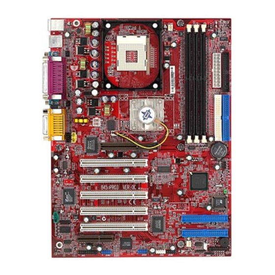
Page 11: Mainboard Layout
Bottom: Line-Out Line-In AGP Slot PCI Slot 1 PCI Slot 2 ICH 2 PCI Slot 3 JBAT1 PCI Slot 4 JPHN1 PCI Slot 5 SFAN1 JWOL1 JFP1 (optional) USB3 JAU1 JMDM1 JUSB2 F_P2 (optional) 845 Ultra (MS-6398 v1.X) ATX Mainboard... - Page 12 AGP Slot PCI Slot 1 PCI Slot 2 ICH 2 PCI Slot 3 JBAT1 PCI Slot 4 JPHN1 IDE 4 PCI Slot 5 IDE 3 SFAN1 JWOL1 JFP1 (optional) USB3 JAU1 JMDM1 JUSB2 F_P2 (optional) 845 Ultra-AR (MS-6398 v1.X) ATX Mainboard...
- Page 13 PCI Slot 2 ICH 2 JBAT1 PCI Slot 3 PCI Slot 4 JPHN1 IDE 4 PCI Slot 5 IDE 3 SFAN1 JWOL1 JFP1 USB 2.0 (optional) JUSB4 JAU1 JUSB3 USB3 JMDM1 JUSB2 F_P2 (optional) 845 Ultra-ARU (MS-6398 v1.X) ATX Mainboard...
-
Page 14: Quick Components Guide
Getting Started Quick Components Guide Component Function Reference JWR1 ATX 20-pin power connector See p. 2-7 JPW1 ATX 12V power connector See p. 2-7 JKBMS1 Mouse connector See p. 2-8 JKBMS1 Keyboard connector See p. 2-9 USB Connectors Connecting to USB devices See p. -
Page 15: Key Features
CPU: Intel Pentium 4 processor in the 478 pin package ® ® ATA133 RAID supported by Promise PDC20276 (for 845 Ultra-AR & 845 Ultra-ARU only). USB 2.0 technology (for 845 Ultra-ARU only) C-Media CMI8738/PCI-6ch supports 2/4/6 channel speaker Fuzzy Logic™ III Live BIOS™... -
Page 16: Msi Special Features
Getting Started MSI Special Features Fuzzy Logic™ III The Fuzzy Logic™ III utility allows users to overclock the CPU FSB (Front Side Bus) frequency in the Windows environment. Select the CPU fre- quency you prefer and click Go to apply the frequency or click Save allowing the system to run at the specified frequency each time when the system is powered on. -
Page 17: Pc Alert™ Iii
Chapter 1 PC Alert™ III The PC Alert III is a utility you can find in the CD-ROM disk. The utility is just like your PC doctor that can detect the following PC hardware status during real time operation: * monitor CPU & system temperatures * monitor fan speed(s) * monitor system voltage * monitor chassis intrusion... - Page 18 Getting Started Features: Network Management - Monitoring & remote control Basic System Utilities - Scandisk & Defragment to maintain your HDD 3D Graphics Design - Enables a more friendly user interface Sofware Utilities - SoftCooler Optimized Cooling 1-11...
-
Page 19: D-Bracket
Chapter 1 D-Bracket™ D-Bracket™ is an external USB bracket integrating four Diagnostic LEDs, which use graphic signal display to help users understand their system. The LEDs provide up to 16 combinations of signals to debug the system. The 4 LEDs can debug all problems that fail the system, such as VGA, RAM or other failures. - Page 20 Getting Started D-Bracket Description Processor Initialization - This will show information regarding the processor (like brand name, system bus, etc…) Testing RTC (Real Time Clock) Initializing Video Interface - This will start detecting CPU clock, checking type of video onboard. Then, detect and initialize the video adapter. BIOS Sign On - This will start showing information about logo, processor brand name, etc….
-
Page 21: Live Bios™/Live Driver
To use the function, you need to install the “MSI Live Update Series” application. After installation, the “MSI Live Update Series” icon (as the right view) will appear on the screen. Double click the “MSI Live Update Series” icon, and the following screen will appear. -
Page 22: Chapter 2. Hardware Setup
Hardware Setup Chapter 2. Hardware Setup Hardware Setup This chapter provides you with the information about hardware setup procedures. While doing the installation, be careful in holding the components and follow the installation procedures. For some components, if you install in the wrong orientation, the components will not work properly. -
Page 23: Central Processing Unit: Cpu
Chapter 2 Central Processing Unit: CPU ® ® The mainboard supports Intel Pentium 4 processor in the 478 pin package. The mainboard uses a CPU socket called PGA478 for easy CPU installation. When you are installing the CPU, make sure the CPU has a heat sink and a cooling fan attached on the top to prevent overheating. -
Page 24: Installing The Cpu Fan
Hardware Setup Installing the CPU Fan As processor technology pushes to faster speeds and higher performance, thermal management becomes increasingly important. To dissi- pate heat, you need to attach the CPU cooling fan and heatsink on top of the CPU. Follow the instructions below to install the Heatsink/Fan: Locate the CPU and its retention Position the heatsink onto the reten- mechanism on the motherboard. -
Page 25: Cpu Core Speed Derivation Procedure
Chapter 2 Connect the fan power cable from the mounted fan to the 3-pin fan power connector on the board. fan power cable CPU Core Speed Derivation Procedure CPU Clock 100MHz Core/Bus ratio then CPU core speed Host Clock x Core/Bus ratio 100MHz x 14 1.4GHz Overclocking... -
Page 26: Memory
Hardware Setup Memory The mainboard provides 3 slots for 184-pin, 2.5V DDR DIMM with 4 memory banks. You can install PC1600/PC2100 DDR SDRAM modules on the DDR DIMM slots (DDR 1~3). To operate properly, at least one DIMM module must be installed. DDR DIMM Slots (DDR 1~3) Introduction to DDR SDRAM... -
Page 27: Ddr Module Combination
Chapter 2 DDR Module Combination To enable normal operation, at least one DIMM module should be in- ® stalled on the motherboard. As Intel 82845 chipset supports 4 DDR memory banks at its maximum, the system memory installed can be up to 2GB. All three slots can be single-sidedly or double-sidedly installed with 184- pin DDR DIMM modules. -
Page 28: Power Supply
Hardware Setup Power Supply The mainboard supports ATX power supply for the power system. Be- fore inserting the power supply connector, always make sure that all compo- nents are installed properly to ensure that no damage will be caused. ATX 20-Pin Power Connector: JWR1 This connector allows you to connect to an ATX power supply. -
Page 29: Back Panel
Chapter 2 Back Panel The Back Panel provides the following connectors: Parallel Midi/Joystick Mouse Keyboard USB COM A COM B L-out L-in MIC Mouse Connector: JKBMS1 ® The mainboard provides a standard PS/2 mouse mini DIN connector for ® ® attaching a PS/2 mouse. -
Page 30: Keyboard Connector: Jkbms1
Hardware Setup Keyboard Connector: JKBMS1 ® The mainboard provides a standard PS/2 keyboard mini DIN connector ® ® for attaching a PS/2 keyboard. You can plug a PS/2 keyboard directly into this connector. Pin Definition SIGNAL DESCRIPTION Keyboard DATA Keyboard DATA No connection Ground Keyboard Clock... -
Page 31: Serial Port Connector: Com A & Com B
Chapter 2 Serial Port Connector: COM A & COM B The mainboard offers two 9-pin male DIN connectors for serial port COM A and COM B. The ports are 16550A high speed communication ports that send/receive 16 bytes FIFOs. You can attach a serial mouse or other serial devices directly to them. -
Page 32: Parallel Port Connector: Lpt1
Hardware Setup Parallel Port Connector: LPT1 The mainboard provides a 25-pin female centronic connector for LPT. A parallel port is a standard printer port that supports Enhanced Parallel Port (EPP) and Extended Capabilities Parallel Port (ECP) mode. Pin Definition SIGNAL DESCRIPTION STROBE Strobe... -
Page 33: Connectors
Chapter 2 Connectors The mainboard provides connectors to connect to FDD, IDE HDD, case, modem, LAN, USB Ports, IR module and CPU/System FAN. Floppy Disk Drive Connector: FDD1 The mainboard provides a standard floppy disk drive connector that supports 360K, 720K, 1.2M, 1.44M and 2.88M floppy disk types. FDD1 IrDA Infrared Module Header: IR2 This connector allows you to connect to IrDA Infrared modules. -
Page 34: Hard Disk Connectors: Ide1 & Ide2
Hardware Setup Hard Disk Connectors: IDE1 & IDE2 The mainboard has a 32-bit Enhanced PCI IDE and Ultra DMA 33/66/100 controller that provides PIO mode 0~4, Bus Master, and Ultra DMA/33/66/100 function. You can connect up to four hard disk drives, CD-ROM, 120MB Floppy (reserved for future BIOS) and other devices. -
Page 35: Ata133 Raid Connectors: Ide3 & Ide4
Chapter 2 ATA133 RAID Connectors: IDE3 & IDE4 (for 845 Ultra-AR & 845 Ultra-ARU only) The 845 Ultra-AR & 845 Ultra-ARU mainboards offer high-end Ultra ATA/133 RAID (0 or 1) hard drive interface specifications supported through ® Promise PDC20276 controller . -
Page 36: Cd-In Connector: Jcd1
Hardware Setup CD-In Connector: JCD1 The connector is for CD-ROM audio connector. Aux Line-In Connector: JAUX1 The connector is for DVD add-on card with Line-in connector. Modem-In Connector: JPHN1 The connector is for modem with internal audio connector. JAUX1 JCD1 JPHN1 Mono_Out Phone_In... -
Page 37: Fan Power Connectors: Cfan1/Sfan1/J7
Chapter 2 Fan Power Connectors: CFAN1/SFAN1/J7 The CFAN1 (processor fan), J7 (chipset fan) & SFAN1 (system fan) sup- port system cooling fan with +12V. It supports three-pin head connector. When connecting the wire to the connectors, always take note that the red wire is the positive and should be connected to the +12V, the black wire is Ground and should be connected to GND. -
Page 38: Wake On Ring Connector: Jmdm1
Hardware Setup Wake On Ring Connector: JMDM1 This connector allows you to connect to a modem card with Wake On Ring function. The connector will power up the system when a signal is re- ceived through the modem card. MDM_WAKEUP 5VSB JMDM1 Wake On LAN Connector: JWOL1... -
Page 39: Front Panel Connector: Jfp1 Or F_P2
Chapter 2 Front Panel Connector: JFP1 or F_P2 The mainboard provides one front panel connector for electrical connec- tion to the front panel switches and LEDs. Users can choose either the JFP1 or the F_P2 depending on their needs. The difference between JFP1 & F_P2 is ®... -
Page 40: Front Panel Audio Connector: Jau1
Hardware Setup Front Panel Audio Connector: JAU1 You can connect an optional audio connector to the JAU1 front panel ® audio connector. The JAU1 is compliant to Intel Front Panel I/O Connectivity Design Guide. JAU1 Pin Definition SIGNAL DESCRIPTION AUD_MIC Front panel microphone input signal AUD_GND Ground used by analog audio circuits... -
Page 41: Front Usb Connectors: Jusb2/3/4 & Usb3
USB ports for front panel. 845 Ultra/ 845 Ultra-AR USB 1.1: The 845 Ultra & 845 Ultra-AR mainboards come with one standard USB 1.1 ® pin header USB3 that is compliant with Intel I/O Connectivity Design Guide. - Page 42 Hardware Setup 845 Ultra-ARU USB 1.1: The 845 Ultra-ARU mainboard comes with one standard USB 1.1 pin header ® USB3 that is compliant to Intel I/O Connectivity Design Guide. An op- tional JUSB2 header (MSI spec) would be available upon request.
- Page 43 Chapter 2 To Attach the Optional USB 2.0 Ports: 1. Take out the USB 2.0 bracket 2. Locate the JUSB3 and JUSB4 pin headers on the motherboard. 3. Connect the USB cables from USB 2.0 bracket to the JUSB3 and JUSB4 connectors separately.
-
Page 44: D-Bracket™ Connector: J10
Hardware Setup D-Bracket™ Connector: J10 The mainboard comes with a J10 connector for you to connect to D- Bracket™. D-Bracket™ is a USB Bracket integrating four LEDs and allows users to identify system problem through 16 various combinations of LED signals. -
Page 45: Jumpers
Chapter 2 Jumpers The motherboard provides one jumper for you to set the computer’s function. This section will explain how to change your motherboard’s function through the use of the jumper. Clear CMOS Jumper: JBAT1 There is a CMOS RAM on board that has a power supply from external battery to keep the data of system configuration. -
Page 46: Slots
Hardware Setup Slots The motherboard provides five 32-bit Master PCI bus slots, one AGP slot and one CNR slot. AGP Slot PCI Slots CNR Slot AGP (Accelerated Graphics Port) Slot The AGP slot allows you to insert the AGP graphics card. AGP is an interface specification designed for the throughput demands of 3D graphics. -
Page 47: Cnr (Communication Network Riser)
Chapter 2 expansioncard to make any necessary hardware or software settings for the expansion card, such as jumpers, switches or BIOS configuration. CNR (Communication Network Riser) The CNR slot allows you to insert the CNR expansion cards. CNR is a specially designed network, audio, or modem riser card for ATX family motherboards. -
Page 48: Chapter 3. Bios Setup
BIOS Setup Chapter 3. BIOS Setup BIOS Setup This chapter provides information on the BIOS Setup program and allows you to configure the system for optimum use. You may need to run the Setup program when: An error message appears on the screen during the system booting up, and requests you to run SETUP. -
Page 49: Entering Setup
Chapter 3 Entering Setup Power on the computer and the system will start POST (Power On Self Test) process. When the message below appears on the screen, press <DEL> key to enter Setup. DEL:Setup F11:Boot Menu F12:Network boot TAB:Logo If the message disappears before you respond and you still wish to enter Setup, restart the system by turning it OFF and On or pressing the RESET button. -
Page 50: Control Keys
BIOS Setup Control Keys <↑> Move to the previous item Move to the next item <↓> Move to the item in the left hand <←> <→> Move to the item in the right hand <Enter> Select the item <Esc> Jumps to the Exit menu or returns to the main menu from a submenu <+/PU>... -
Page 51: The Main Menu
Chapter 3 The Main Menu Once you enter AMIBIOS SIMPLE SETUP UTILITY, the Main Menu will ap- pear on the screen. The Main Menu displays twelve configurable functions and two exit choices. Use arrow keys to move among the items and press <Enter>... - Page 52 BIOS Setup Integrated Peripherals Use this menu to specify your settings for integrated peripherals. Hardware Monitor Setup This entry shows your PC’s current status, and allows you to adjust CPU clock, core voltage, ratio and DDR voltage. Load High Performance Defaults Use this menu to load the BIOS values for the best system performance, but the system stability may be affected.
-
Page 53: Standard Cmos Features
Chapter 3 Standard CMOS Features The items inside STANDARD CMOS SETUP menu are divided into 9 catego- ries. Each category includes none, one or more setup items. Use the arrow keys to highlight the item you want to modify and use the <PgUp> or <PgDn> keys to switch to the value you prefer. - Page 54 BIOS Setup Pri Master/Pri Slave/Sec Master/Sec Slave Press PgUp/<+> or PgDn/<-> to select the hard disk drive type. The specifica- tion of hard disk drive will show up on the right hand according to your selection. TYPE Type of the device. SIZE Capacity of the device.
-
Page 55: Advanced Bios Features
Chapter 3 Advanced BIOS Features Quick Boot Setting the item to Enabled allows the system to boot within 5 seconds since it will skip some check items. Available options: Enabled and Disabled. Full Screen Logo Show This item enables you to show the company logo on the bootup screen. Set- tings are: Disabled Shows the POST messages at boot. - Page 56 BIOS Setup as LS-120 or ZIP drive, that functions as a floppy drive. ARMD-HDD The system will boot from ARMD device, such as MO or ZIP drive, that functions as hard disk drive. CDROM The system will boot from the CD-ROM. SCSI The system will boot from the SCSI.
- Page 57 Chapter 3 Swap Floppy Setting to Enabled will swap floppy drives A: and B:. Seek Floppy This setting causes the BIOS to search for floppy disk drives at boot time. When enabled, the BIOS will activate the floppy disk drives during the boot process: the drive activity light will come on and the head will move back and forth once.
- Page 58 BIOS Setup L1 Cache Cache memory is additional memory that is much faster than conventional DRAM (system memory). When the CPU requests data, the system transfers the requested data from the main DRAM into cache memory, for even faster access by the CPU. The setting enables/disables the internal cache (also known as L1 or level 1 cache).
-
Page 59: Advanced Chipset Features
Chapter 3 Advanced Chipset Features Note: Change these settings only if you are familiar with the chipset. DRAM Frequency Use this item to configure the clock frequency of the installed DRAM. Settings are: Auto, 200MHz, 266MHz. Configure DRAM Timing by This setting determines whether DRAM timing is controlled by the SPD (Serial Presence Detect) EEPROM on the DRAM module. - Page 60 BIOS Setup to be allowed to precharge. If insufficient time is allowed for the RAS to accumulate its charge before DRAM refresh, refresh may be incomplete and DRAM may fail to retain data. This item applies only when synchro- nous DRAM is installed in the system. Setting options: 2 Clocks, 3 Clocks. RAS# to CAS# Delay When DRAM is refreshed, both rows and columns are addressed separately.
-
Page 61: Power Management Setup
Chapter 3 Power Management Setup IPCA Function This item is to activate the ACPI (Advanced Configuration and Power Man- agement Interface) function. If your operating system is ACPI-aware, such as Windows 98SE/2000/ME, select Yes. Available options: Yes and No. ACPI Standby State This item specifies the power saving modes for ACPI function. - Page 62 BIOS Setup (Suspend to RAM) sleep state. Settings: Enabled and Disabled. Mouse Wakeup From S3 This item allows the activity of the mouse to wake up the system from S3 (Suspend to RAM) sleep state. Settings: Enabled and Disabled. Keyboard Wakeup From S3 This item allows the activity of the keyboard to wake up the system from S3 (Suspend to RAM) sleep state.
- Page 63 Chapter 3 Power Button Function This feature sets the function of the power button. Settings are: On/Off The power button functions as normal on/off button. Suspend When you press the power button, the computer enters the suspend/sleep mode, but if the button is pressed for more than four seconds, the computer is turned off.
- Page 64 BIOS Setup Power Again This setting specifies whether your system will reboot after a power failure or interrupts occurs. Available settings are: Power Off Leaves the computer in the power off state. Power On Reboots the computer. Last State Restores the system to the status before power failure or interrupt occurs.
-
Page 65: Pnp/Pci Configurations
Chapter 3 PNP/PCI Configurations This section describes configuring the PCI bus system and PnP (Plug & Play) feature. PCI, or Personal Computer Interconnect, is a system which allows I/O devices to operate at speeds nearing the speed the CPU itself uses when communicating with its special components. - Page 66 BIOS Setup VGA Palette Snoop Bit Setting Action Disabled Data read or written by the CPU is only directed to the PCI VGA device’s palette registers. Enabled Data read or written by the CPU is directed to both the PCI VGA device’s palette registers and the ISA VGA device’s palette registers, permitting the palette regis- ters of both VGA devices to be identical.
-
Page 67: Integrated Peripherals
On-Chip IDE This setting controls the on-chip IDE controller. Setting options: Disabled, Primary, Secondary, Both. Onboard ATA133 RAID Chip (for 845 Ultra-AR/845 Ultra-ARU mainboard) This allows you to enable/disable the onboard ATA133 RAID controller. Set- ting options: Disabled, Enabled. Onboard Audio Chip This setting is used to enable or disable the onboard audio controller. - Page 68 BIOS Setup AC’97 Audio Auto allows the mainboard to detect whether an audio device is used. If the device is detected, the onboard AC’97 (Audio Codec’97) controller will be enabled; if not, it is disabled. Disable the controller if you want to use other controller cards to connect an audio device.
- Page 69 Chapter 3 IR Pin Select Set to IRRX/IRTX when using an internal IR module connected to the IR connector. Set to SINB/SOUTB. when connecting an IR adapter to COM Parallel Port This field specifies the base I/O port address of the onboard parallel port. Selecting Auto allows AMIBIOS to automatically determine the correct base I/ O port address.
-
Page 70: Hardware Monitor Setup
BIOS Setup Hardware Monitor Setup This section describes how to set the Chassis Intrusion feature, CPU FSB frequency, monitor the current hardware status including CPU/system temperatures, CPU/System Fan speeds, Vcore etc. Monitor function is avail- able only if there is hardware monitoring mechanism onboard. CPU Ratio Selection This setting controls the multiplier that is used to determine the internal clock speed of the processor relative to the external or motherboard clock speed. - Page 71 Chapter 3 may just cause your overclocked processor to lock up. DDR/AGP Power Voltage The item is to adjust the DDR/AGP voltage to increase the DDR/AGP rate. Modifying the setting may lead to unstable system, so changing the DDR/ AGP Vcore for long-term use is not recommended. CPU Vcore Adjust This setting is used to adjust the CPU core voltage (Vcore), making overclocking possible.
-
Page 72: Load High Performance/Bios Setup Defaults
BIOS Setup Load High Performance/BIOS Setup Defaults The two options on the main menu allow users to restore all of the BIOS settings to High Performance defaults or BIOS Setup defaults. The High Per- formance Defaults are the default values set by the mainboard manufacturer for the best system performance but probably will cause a stability issue. - Page 73 Chapter 3 When you select Load BIOS Setup Defaults, a message as below appears: Pressing ‘Y’ loads the default values that are factory settings for stable system performance. 3-26...
-
Page 74: Supervisor/User Password
BIOS Setup Supervisor/User Password When you select this function, a message as below will appear on the screen: Type the password, up to six characters in length, and press <Enter>. The password typed now will replace any previously set password from CMOS memory. - Page 75 Chapter 3 thorized use of your computer. The setting to determine when the password prompt is required is the PASSWORD CHECK option of the ADVANCED BIOS FEATURES menu. If the PASSWORD CHECK option is set to Always, the password is required both at boot and at entry to Setup. If set to Setup, pass- word prompt only occurs when you try to enter Setup.
-
Page 76: Ide Hdd Auto Detection
BIOS Setup IDE HDD AUTO Detection You can use this utility to AUTOMATICALLY detect the characteristics of most hard drives. 3-29... -
Page 77: Appendix A: Using 4-/6-Channel Audio Function
Using 4-/6-channel Audio Function Appendix A: Using 4-/6-channel Audio Function Using 4-/6-channel Audio Function The mainboard comes with C-Media 6-channel audio function, which allows you to attach 4 or 6 speakers for better space sound effect. The section will tell you how to activate 4-/6-channel audio function. TOPICS Installing C-Media Drivers Hardware Configuration... -
Page 78: Installing C-Media Drivers
Appendix A Installing C-Media Drivers The mainboard is able to transform the audio connectors on the back panel from 2-channel to 4-/6-channel. To use the function, you need to install the C- Media drivers. To install C-Media drivers: Insert the companion CD into the CD-ROM drive. The setup screen will automatically appear. -
Page 79: Software Configuration
Using 4-/6-channel Audio Function Software Configuration To have 4-/6-channel audio work, you must set appropriate configuration in the C-Media software application. To set the multi-channel configuration: Click the C-Media Mixer icon from the window tray on the bottom. The following screen appears. Click the indicated button. Click here The “Advanced”... -
Page 80: Appendix B: Msi Smart Key
Appendix B: MSI Smart Key MSI Smart Key If security is important to you, the MSI Smart Key is the best solution to prevent your data in the computer from being accessed by unauthorized people. In the public workspace, the passwords (BIOS password, system password, etc.) are not enough to keep your privacy. -
Page 81: Installing Msi Smart Key
The following sections will provide the detailed instructions for the BIOS setup and software installation. System Requirements Before you use the MSI Smart Key, please check the hardware, soft- ware and operating system requirements first. Operating System Windows 98/ME/2000/XP... -
Page 82: Using Msi Smart Key
The message as below appears on the screen asking you to enable or disable the key: Welcome to MSI Smart Key, please press “Y” to begin, press “N” to exit Type <Y> to enable it; type <N> to disable it and bypass the BIOS to enter the operating system. - Page 83 Note: 1. You should firmly remember the password you set; if the Smart Key is lost, you can get a new key from MSI, and turn on the computer with the original password. 2. To avoid the password from being forgotten, we provide the table below for you to keep note in this guide.
- Page 84 The message as below appears on the screen asking you to enable or disable the key: If you want to disable MSI Smart Key, please press “Y”, or press “N” to exit Type <Y> to disable it; type <N> to keep the function enabled and enter the operating system.
- Page 85 Appendix B Boot up with no key /wrong key/new key installed Once the MSI Smart Key is enabled, always keep the key inserted in the computer. If the key is unplugged, the other user can not access the computer. The message as below appears during the system booting up:...
- Page 86 MSI Smart Key Software Setup When the Smart Key is inserted into your computer and the software application is installed in the operating system, it will serve as a safeguard for your system. When the key is unplugged, the operating system will enter protection status immediately and the mouse and keyboard will be locked;...
- Page 87 Appendix B When the Software License Agreement window appears on the screen, press [ Yes ] to continue. Click here Choose the folder to install the software in your computer; simply press [ Next > ] to install it in the default folder. Default folder When the installation is completed, restart the computer as instructed.
- Page 88 MSI Smart Key Using the Software Application When the program is installed in the operating system, it will embed in the system tray and show an icon as below: Smart Key icon Note: When the Smart Key function is disabled in BIOS, this program will not be launched in the operating system.
- Page 89 Appendix B Security Setting This option allows you to logon to Windows automatically. Select the “Auto Login” item and check the “Auto Logon to Windows” item in the Setting Page field to enable the function. Once the function is enabled and set properly, you do not have to type the user’s name and password everytime when entering Windows.
- Page 90 Smart Key is unplugged and the system locked. You can set the monitor to display: a) blank screen b) the retaining screen when the system locked c) MSI Logo The default setting is to show MSI Logo. B-11...
- Page 91 Appendix B Press the “Apply Changes” button to enable the option you choose. Click here Press the “bulb” button at the right-bottom to hide the program in the system tray and keep on monitoring the system. Click here Press the “door” button at the right-bottom to exit the program. Click here B-12...
- Page 92 MSI Smart Key Removing the Software Application To remove the program, follow the steps below: Click and choose Settings → Control Panel; double- click the Add/Remove Programs item to open the “Add/Remove Programs Properties” window. Choose this Click here Select the “SmartKey” item in the field and click the [ Add/ Remove...
-
Page 93: Glossary
Glossary Glossary Glossary ACPI (Advanced Configuration & Power Interface) This power management specification enables the OS (operating system) to control the amount of power given to each device attached to the computer. Windows 98/98SE, Windows 2000 and Windows ME can fully support ACPI to allow users managing the system power flexibly. - Page 94 Glossary example, a modem chipset contains all the primary circuits for transmitting and receiv- ing data; a PC chipset provides the electronic interfaces between all subsystems. CMOS (complementary metal-oxide semiconductor) CMOS is a widely used type of semiconductor, which features high speed and low power consumption.
- Page 95 Glossary ECC Memory (error correcting code memory) A type of memory that contains special circuitry for testing the accuracy of data and correcting the errors on the fly. IDE (Integrated Drive Electronics) A type of disk-drive interface widely used to connect hard disks, CD-ROMs and tape drives to a PC, in which the controller electronics is integrated into the drive itself, eliminating the need for a separate adapter card.
- Page 96 Glossary PCI (Peripheral Component Interconnect) A local bus standard developed by Intel that first appeared on PCs in late 1993. PCI provides “plug and play” capability and allows IRQs to be shared. The PCI controller can exchange data with the system's CPU either 32 bits or 64 bits at a time. PnP (Plug and Play) A set of specifications that allows a PC to configure itself automatically to work with peripherals.
Need help?
Do you have a question about the 845 Ultra and is the answer not in the manual?
Questions and answers