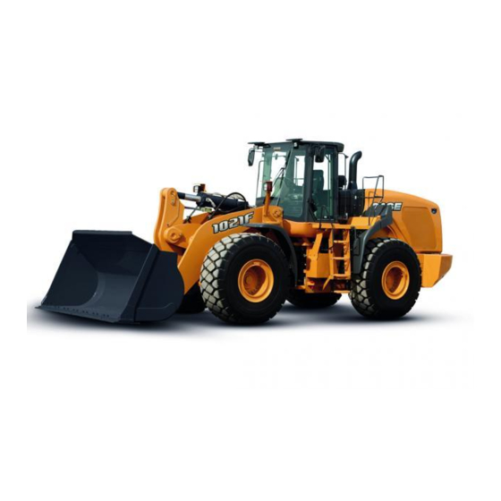
Summary of Contents for Case 1021F
- Page 1 1021F 1121F Tier 4 Wheel Loader SERVICE MANUAL Part number 84555573 1st edition English October 2011...
- Page 2 Contents INTRODUCTION HYDRAULIC, PNEUMATIC, ELECTRICAL, ELECTRONIC SYSTEMS A PRIMARY HYDRAULIC POWER SYSTEM ..........A.10.A ELECTRICAL POWER SYSTEM .
- Page 3 USER CONTROLS AND SEAT Operator seat ......... . . E.32.C USER PLATFORM .
- Page 4 84555573 11/10/2011...
- Page 5 Thanks very much for your reading, Want to get more information, Please click here, Then get the complete manual NOTE: If there is no response to click on the link above, please download the PDF document first, and then click on it. Have any questions please write to me: admin@servicemanualperfect.com...
- Page 6 INTRODUCTION 84555573 11/10/2011...
- Page 7 Contents INTRODUCTION Torque ..................3 Hydraulic contamination .
- Page 8 INTRODUCTION Torque Alternator Alternator pulley retaining nut 95 - 109 N·m (70 - 80 lb ft) Battery terminal nut 6 - 8 N·m (55 - 72 lb in) Indicator light terminal nut 2 - 3 N·m (16 - 24 lb in) Axle Planetary carrier lock screws 200 N·m (148 lb ft)
- Page 9 INTRODUCTION Starter motor mounting bolts 41 - 48 N·m (30 - 35 lb ft) Engine support bracket-to-rear chassis bolts 386 - 434 N·m (285 - 320 lb ft) Engine shock mount nuts 397 - 447 N·m (293 - 330 lb ft) Fuel tank Tighten the fuel sender bolts in the sequence as shown in the image (2) to a torque of 6 - 8 N·m (53 - 71 lb in).
- Page 10 INTRODUCTION RCPH11WHL202AAH Wheel nuts First stage: 278 N·m (205 lb ft). Second stage: 640 - 720 N·m (472 - 531 lb ft) 84555573 11/10/2011...
- Page 11 INTRODUCTION Hydraulic contamination Contamination in the hydraulic system is a major cause of the malfunction of hydraulic components. Contamination is any foreign material in the hydraulic oil. Contamination can enter the hydraulic system in several ways. (A) When you drain the oil or disconnect any line. (B) When you disassemble a component.
- Page 12 INTRODUCTION Capacities 1021F Capacities and specifications Engine Type of oil Case Akcela (SAE 15W-40) Capacity (with filter change) 28.5 l (30.1 US qt) Cooling system System capacity 56.8 l (60.0 US qt) Fuel system System capacity 473.0 l (125.0 US gal)
- Page 13 INTRODUCTION 1121F Capacities and specifications Engine Type of oil Case Akcela (SAE 15W-40) Capacity (with filter change) 28.5 l (30.1 US qt) Cooling system System capacity 56.8 l (60.0 US qt) Fuel system System capacity 473.0 l (125.0 US gal)
- Page 14 INTRODUCTION Engine oil viscosity/Temperature ranges RCPH11WHL023FAH NOTE: Use of an engine oil pan heater or an engine coolant heater may be required when operating temperatures are in Winter or Arctic conditions. Transmission oil viscosity/Temperature ranges RCPH10WHL453BAH 84555573 11/10/2011...
- Page 15 INTRODUCTION Hydraulic/Brake system - temperature range RCPH10WHL006EAL 84555573 11/10/2011...
- Page 16 Transmission component oil Extreme pressure oil should be used for enclosed transmission components. Choose an oil that is manufactured for your climate/temperature conditions such as Case Nexplore or CNH F200A. See charts at the beginning of this section. Grease...
- Page 17 See charts at the beginning of this section to choose the correct oil for climate/temperatures. If Case Akcela engine oil cannot be obtained, use only oil of the API SERVICE CI-4 category. NOTE: Do not put any Performance Additive or other ad- ditive in the sump.
- Page 18 SERVICE MANUAL HYDRAULIC, PNEUMATIC, ELECTRICAL, ELECTRONIC SYSTEMS 84555573 11/10/2011...
- Page 19 FAULT CODES ................A.50.A 1021F , 1121F...
- Page 20 HYDRAULIC, PNEUMATIC, ELECTRICAL, ELECTRONIC SYSTEMS - A PRIMARY HYDRAULIC POWER SYSTEM - 10.A 84555573 11/10/2011 A.10.A / 1...
- Page 21 Hydraulic schematic frame 01 - 1021F/1121F Wheel Loader ....... . .
- Page 22 HYDRAULIC, PNEUMATIC, ELECTRICAL, ELECTRONIC SYSTEMS - PRIMARY HYDRAULIC POWER SYSTEM PRIMARY HYDRAULIC POWER SYSTEM - Dynamic description – Hydraulic Oil Supply The wheel Loaders use a combination of variable displacement Pressure and Flow Compensated (PFC) piston type pump and a gear type pump open-center hydraulic system. The closed center variable PFC hydraulic system supplies the oil flow requirements for: Steering •...


Need help?
Do you have a question about the 1021F and is the answer not in the manual?
Questions and answers