Table of Contents
Advertisement
Quick Links
REDI-MIG 325 Remote
Semi Automatic Arc Welding Machine
This manual applies to
Part No.
Code
Description
KA1434-2
1567
REDI-MIG 325
Remote
& above
Lincoln Electric welders are designed and built with safety in mind. However, your overall safety can be
increased by proper installation and thoughtful operation on your part. Read and observe the general safety
precautions on page 2 and follow specific installation and operating instructions included in this manual.
Associated Subsidiaries in Australasia, Asia, Canada, Europe, North and South America.
THE WORLD'S LEADER IN WELDING AND CUTTING PRODUCTS
OPERATING MANUAL
Volts
415
SAFETY DEPENDS ON YOU
Most importantly, think before you act and be careful.
THE LINCOLN ELECTRIC COMPANY
(AUSTRALIA) PTY. LTD.
SYDNEY. AUSTRALIA
A Subsidiary of
THE LINCOLN ELECTRIC CO. U.S.A.
A.B.N. 36 000 040 308
IMA 599B
November 2003
EMC Compliant
Advertisement
Table of Contents
Troubleshooting

Subscribe to Our Youtube Channel
Related Manuals for Lincoln Electric REDI-MIG 325 Remote


Summary of Contents for Lincoln Electric REDI-MIG 325 Remote
- Page 1 EMC Compliant SAFETY DEPENDS ON YOU Lincoln Electric welders are designed and built with safety in mind. However, your overall safety can be increased by proper installation and thoughtful operation on your part. Read and observe the general safety precautions on page 2 and follow specific installation and operating instructions included in this manual.
- Page 2 PROTECT YOURSELF AND OTHERS FROM POSSIBLE SERIOUS INJURY OR DEATH. READ AND UNDERSTAND BOTH THE SPECIFIC INFORMATION GIVEN IN THE OPERATING MANUAL FOR THE WELDER AND/OR OTHER EQUIPMENT TO BE USED AS WELL AS THE FOLLOWING GENERAL INFORMATION. ARC WELDING SAFETY PRECAUTIONS ARC RAYS can burn ELECTRIC SHOCK can kill 1.
- Page 3 3. Should the primary cord be damaged, a special cord is required, and is available from Lincoln Electric. 4. Parts should be ordered from Lincoln, its offices or the nearest Authorised Field Service Shop. (The “Lincoln Service Directory”...
- Page 4 WELDING, EMF & PACEMAKERS All welders should follow safe practices that minimise their Welders with pacemakers exposure to electric and magnetic fields (EMF). There is no question that the fields in arc welding can interfere For welders wearing implanted pacemakers, safe welding with a pacemakers function.
-
Page 5: Instructions For Electromagnetic Compatibility
Welding equipment should be connected to the mains supply reproduced from British Standard EN 50199) according to the manufacturer’s recommendations.If interference • for using with other Lincoln Electric/LiquidArc equipment. occurs, it may be necessary to take additional precautions such • designed for industrial and professional use. - Page 6 Thank You for selecting a QUALITY product by Lincoln Electric. We want you to take pride in operating this Lincoln Electric Company product - as much pride as we have in bringing this product to you! Please record your equipment identification information below for future reference. This information can be found on your machine nameplate.
- Page 7 Section 7 ACCESSORIES Section 8 GROUND TEST PROCEDURE Section 9 TROUBLESHOOTING PARTS LISTS REDI-MIG 325 Remote WIRING DIAGRAM REDI-MIG 325 Remote PARTS LISTS REDI-MIG 4D Remote WIRING DIAGRAM REDI-MIG 4D Remote Wire Feeder WIRE DRIVE ASSEMBLY PARTS LIST REDI-MIG 360 TORCH...
-
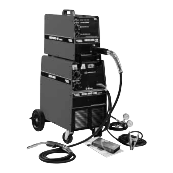
Page 8: Product Description
PRODUCT DESCRIPTION The REDI-MIG 325 Remote offers a remote wire feeder and a separate Constant Voltage DC arc welding machine. It combines a solid state power source with electronically controlled wire feeding equipment. Excellent arc characteristics are provided for both gas shielded and self shielded welding within its current range. -
Page 9: Shielding Gas Supply (For The Gas Metal Arc Welding Process)
The control cable connects to the plug in the tool storage with a spanner. area of the REDI-MIG 325 Remote power source, below the output studs. Before opening the cylinder valve, turn the regulator... -
Page 10: Section 2 - Operating Instructions
Section 2 - OPERATING INSTRUCTIONS 2.2 Control Panel WARNING Power Switch • Do not touch electrically live The mains power switch is incorporated in the “coarse” parts or electrode with skin or output voltage control rotary switch. In the “OFF” position wet clothing. -
Page 11: Section 3 - Setting Up For Welding
Burnback Control * Use this same toggle switch to operate the wire feed motor and “cold” inch the wire, by pushing the toggle switch This control is located in the wire feed bay. The burnback downwards. control adjusts the time period from when the drive motor stops until the power source and gas solenoid are switched 2 Step/4 Step Trigger Operation * off. - Page 12 Page 12 REDI-MIG 325 IMA 599B...
-
Page 13: Section 4 - Welding
Cored Wire 4 Step trigger mode should only be used for long welds by experienced operators. * Standard on REDI-MIG 325 Remote. 4.1 Changing Electrode Size and Type 4.2 Adjusting Spool Tension When changing the electrode size or type, ensure the wire feed drive roll is the correct size and type for the electrode. -
Page 14: Process Selection
5.2 The Self-Shielded (Gasless) When comparing the GMAW and FCAW processes, you can see that the principal difference between the two lies in FCAW Welding Arc (DC-) the type of shielding used. GMAW uses gas for shielding, thus we have Gas Metal Arc Welding. FCAW uses the Figure 1 illustrates the action taking place in the self melting or burning of the core ingredients for shielding, and shielded gasless FCAW welding arc. -
Page 15: Welding Techniques For The Self-Shielded (Gasless) Fcaw Process
5.7 Welding Techniques For The Self- Figure 4 Shielded (Gasless) FCAW Process Four simple manipulations are of prime importance when Contact Tip welding. With complete mastery of the four, welding will be easy. They are as follows: Wire Electrode 1. The Correct Welding Position 10 - 12 mm Electrical Stickout Figure 3 illustrates the correct welding position for right... -
Page 16: Welding Techniques For The Gmaw (Mig) Process
Gas Shielded GCAW Processes 6. When no more welding is to be done, close the valve The REDI-MIG 325 Remote comes ready for welding using on the gas cylinder, momentarily operate the gun the MIG process. -
Page 17: Joint Types And Positions
Refer to Figure 4. Unless a butt weld penetrates close to 100% of the metal For the REDI-MIG 325 Remote, use the following: thickness, a butt weld will be weaker than the material welded together. In the example shown in Figure 12, the Mild Steel Sheet (1.6 mm) -
Page 18: Fillet Welds
Figure 13 The important thing is to continue lowering the entire arm as the weld is made so the angle of the gun does not change. Move the electrode wire fast enough that the slag does not catch up with the arc. Vertical-down welding gives thin, shallow welds. -
Page 19: Section 6 - Maintenance
All drive rolls are stamped with the wire sizes they will feed. If a wire size other than that stamped on the roll is to be The REDI-MIG 325 Remote has built-in protective used, the drive roll must be changed. -
Page 20: Section 7 - Accessories
6.5 Liner Removal, Installation and Trimming Insert a new untrimmed liner into the connector end of the cable. Instructions for REDI-MIG 360Torch Fully seat the liner bushing into the Euro connector. Tighten Note: The variation in cable lengths prevents the inter- the liner nut cap on the brass cable connector. -
Page 21: Section 9 - Troubleshooting
Section 9 - TROUBLESHOOTING WARNING • Have an electrician install and service this equipment. • Turn the input power off at the fuse box and unplug the machine before working on equipment. ELECTRIC • Do not touch electrically hot SHOCK parts. - Page 22 TROUBLESHOOTING What To Do Problem Possible Cause No wire feed, although arc Defective wire feed motor or wire drive Measure the voltage between the motor voltage is present. control PC board. leads (54) and (53) when the Gas Purge/Wire Inch toggle switch is pressed downwards.
- Page 23 AP-58 Operative: Nov 2003 Supersedes: May 2001 REDI-MIG 325 Remote KA1434-2 (415V) KA1434-12 (380V) Model Index DO NOT attempt to use this Parts List for machine if its code NUMBERS IN THE TABLE BELOW INDICATE WHICH number is not listed. Contact the Service Department for any COLUMN TO USE IN EACH PARTS LIST FOR EACH code numbers not listed.
-
Page 24: General Assembly
AP-58C General Assembly Operative: Nov 2003 Supersedes: May 2001 DETAIL A Mounts Ite m 106 Mounts Ite m 106 Ref: AG1417-4 (A13-10-99) REDI-MIG 325 Page 24 IMA 599B... - Page 25 AP-58-C1 Operative: Nov 2003 Supersedes: May 2001 v# Indicates a change this printing. * Items not illustrated. Use only the parts marked “X” in the column under the heading number called for in the model index page. Recommended Spare Parts are highlighted in bold Nut, bolt and washer sizes are given so they may be procured locally.
- Page 26 AP-58-C2 General Assembly Operative: Nov 2003 Supersedes: May 2001 DETAIL A DECAL PLACEMENT Ref: AG1417-4 (A13-10-99) REDI-MIG 325 Page 26 IMA 599B...
- Page 27 AP-58-C3 Operative: Nov 2003 Supersedes: May 2001 # Indicates a change this printing. * Items not illustrated. Use only the parts marked “X” in the column under the heading number called for in the model index page. Recommended Spare Parts are highlighted in bold Nut, bolt and washer sizes are given so they may be procured locally.
-
Page 28: Front Panel Assembly
ITEM DESCRIPTION PART NO. QTY. Front Panel AL2677 Pilot Light, 240v, Amber AT3384-1 Led Light, 24v, Amber AS4460-1 Nameplate REDI-MIG 325 Remote AL2691-4 Voltmeter 0-50V DC AM3397-1 Ammeter 0-400A DC am3398-1 Fastener Button T14659-1 Bushing 41.3 i.d. T12380A1 Lead /43A (Temp Lt to Rect Thermo) AM3040B570 Resistor, Diode &... -
Page 29: Cover Panels
AP- 58-E Cover Panels Operative: Nov 2003 Supersedes: May 2001 N.A. N.A. Ref: AM3608 (A13-10-99) AP- 58-E1 Operative: May 2001 Supersedes: # Indicates a change this printing. * Items not illustrated. Use only the parts marked “X” in the column under the Recommended Spare Parts are highlighted in bold heading number called for in the model index page. - Page 30 AP- 58-W Wiring Diagram Operative: May 2001 Supersedes: 325 Remote Page 30 REDI-MIG 325 IMA 599B...
- Page 31 AP-56 Operative: Nov 2003 Supersedes: May 2001 REDI-MIG 4D Remote KA1435 Model Index DO NOT attempt to use this Parts List for machine if its code NUMBERS IN THE TABLE BELOW INDICATE WHICH number is not listed. Contact the Service Department for any COLUMN TO USE IN EACH PARTS LIST FOR EACH code numbers not listed.
-
Page 32: Panel Assembly
AP-56C Panel Assembly Operative: Nov 2003 Supersedes: May 2001 AG 1412-1 (A14-4-00) REDI-MIG 325 Page 32 IMA 599B... - Page 33 AP- 56-C1 Operative: Nov 2003 Supersedes: May 2001 # Indicates a change this printing. * Items not illustrated. Use only the parts marked “X” in the column under the heading number called for in the model index page. Recommended Spare Parts are highlighted in bold Nut, bolt and washer sizes are given so they may be procured locally.
- Page 34 NOTES REDI-MIG 325 Page 34 IMA 599B...
- Page 35 AP- 56W Wiring Diagram Operative: May 2001 Supersedes: 4D Remote IMA 599B REDI-MIG 325 Page 35...
-
Page 36: Wire Drive Assembly
AP-56-D Wire Drive Assembly Operative: Supersedes: 5,6,7,8 10,11,12 Ref: AM3391 REDI-MIG 325 Page 36 IMA 599B... - Page 37 AP-56-D1 Operative: Supersedes: # Indicates a change this printing. * Items not illustrated. Use only the parts marked “X” in the column under the heading number called for in the model index page. Recommended Spare Parts are highlighted in bold Nut, bolt and washer sizes are given so they may be procured locally.
- Page 38 AP-49E REDI-MIG 360 Torch Operative: Nov 2003 Supersedes: May 2001 REDI-MIG 325 Page 38 IMA 599B...
- Page 39 AP-49-E1 Operative: Nov 2003 Supersedes: # Indicates a change this printing. * Items not illustrated. Use only the parts marked “X” in the column under the Recommended Spare Parts are highlighted in bold heading number called for in the model index page. Nut, bolt and washer sizes are given so they may be procured locally.
- Page 40 We respond to our customers based on the best information in our One Year* possession at that time. Lincoln Electric is not in a position to warrant or guarantee Ruggerini Engines and Accessories such advice and assumes no liability, with respect to such information or advice. We...
Need help?
Do you have a question about the REDI-MIG 325 Remote and is the answer not in the manual?
Questions and answers