RACOM RipEX2 User Manual
Radio modem & router
Hide thumbs
Also See for RipEX2:
- User manual (326 pages) ,
- User manual (185 pages) ,
- User manual (131 pages)

Related Manuals for RACOM RipEX2


Summary of Contents for RACOM RipEX2
- Page 1 User manual RipEX2 Radio modem & Router fw 2.0.8.0 2022-03-07 version 1.19 RACOM s.r.o. | Mirova 1283 | 592 31 Nove Mesto na Morave | Czech Republic www.racom.eu Tel.: +420 722 937 522 | E -mail: racom@racom.eu...
-
Page 3: Table Of Contents
7.1.2.5.3. Base station - List of Remote stations ..........70 7.1.2.5.4. Radio protocol - Remote station ............71 7.1.2.6. Flexible Protocol (router mode) ..............71 7.1.2.6.1. Individual link option ................72 7.1.2.7. Advanced radio parameters ................. 72 © RACOM s.r.o. – RipEX2 Radio modem & Router... - Page 4 7.2.4.3. Neighbors ....................117 7.2.4.4. Static rules ....................119 7.2.4.5. Import IGP filter ................... 119 7.2.4.6. Export IGP filter ..................120 7.2.4.7. Import OUT rules ..................121 7.2.4.8. Export OUT filter ..................122 RipEX2 Radio modem & Router – © RACOM s.r.o.
- Page 5 8.4. Statistics ........................... 173 8.4.1. Parameters ......................174 8.4.2. Radio interface statistics ..................175 8.4.3. Radio protocol statistics ..................176 8.4.4. Radio protocol non-addressable statistics ............. 177 8.4.5. Radio signal statistics .................... 177 © RACOM s.r.o. – RipEX2 Radio modem & Router...
- Page 6 10.9. Compliance Federal Communications Commission and Innovation, Science and Eco- nomic Development Canada ....................233 10.10. Compliance ANATEL Brasil ..................240 10.11. Warranty ........................240 10.12. RipEX2 Availability and service life time ..............240 10.13. RipEX2 maintenance ....................241 A. Abbreviations ..........................243 B. Proprietary UDP ports ......................... 245 Index ..............................
- Page 7 RipEX2 Radio modem & Router 1.1. Connecting RipEX2 to a PC over WiFi, ETH/USB adapter, ETH interface ........ 10 1.2. RipEX2 bench testing ......................... 12 2.1. RipEX2 dimensions ........................14 2.2. RipEX2 dimensions – bottom ..................... 15 2.3. RipEX2 with DIN rail ........................15 2.4.
- Page 8 10.3. Minimum Safety Distance 135–175 MHz according to RSS-102 .......... 223 10.4. Maximum voltage and current of individual interfaces ............224 10.5. Compliance FCC and ISED ....................233 B.1. RipEX2 proprietary UDP ports ....................245 RipEX2 Radio modem & Router – © RACOM s.r.o.
-
Page 9: Important Notice
© 2021 RACOM. All rights reserved. Sole owner of all rights to this User manual is the company RACOM s. r. o. (in this manual referred to under the abbreviated name RACOM). Drawing written, printed or reproduced copies of this manual or records on various media or translation of any part of this manual to foreign languages (without written consent of the rights owner) is prohibited. -
Page 10: Quick Guide
). The ETH/USB contains a built-in DHCP server, so if you have a DHCP client in your PC as most users, you do not need to set anything up. The default IP address of RipEX2 unit, for access over the ETH/USB adapter, is 10.9.8.7. -
Page 11: Bench Testing
Section 2.2.9, “HW button”. 1.1. Bench testing Before installing a RipEX2 network in the field, a bench-test should be performed in the lab. The RipEX2 Demo case is great for this as it contains everything necessary: 3× RipEX2 unit, Power supply, dummy load antennas, etc. - Page 12 Quick guide Fig. 1.2: RipEX2 bench testing RipEX2 Radio modem & Router – © RACOM s.r.o.
-
Page 13: Product
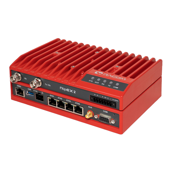
2. Product RipEX2 is a radio modem platform renowned for overall data throughput in any real-time environment. RipEX2 radio modems are native IP devices, Software Defined with Linux OS that have been designed with attention to detail, performance and quality. -
Page 14: Dimensions
Product 2.1. Dimensions Fig. 2.1: RipEX2 dimensions RipEX2 Radio modem & Router – © RACOM s.r.o. -
Page 15: Ripex2 Dimensions - Bottom
Fig. 2.2: RipEX2 dimensions – bottom 134,7 125,5 DIN Rail Clip DIN 35 Rail Fig. 2.3: RipEX2 with DIN rail For more information see Section 4.1.1, “DIN rail mounting” and Section 4.1.2, “Flat mounting”. © RACOM s.r.o. – RipEX2 Radio modem & Router... -
Page 16: Ripex2 Dimensions With Connectors
Product 10,2 22,1 17,8 31,6 42,7 32,8 47,3 Fig. 2.4: RipEX2 dimensions with connectors Fig. 2.5: RipEX2- with optional cellular interface dimensions RipEX2 Radio modem & Router – © RACOM s.r.o. -
Page 17: Connectors
(separated Tx and Rx antennas or full duplex operation with duplexer) - Rx for receiving and Tx/Rx for transmitting. Warning RipEX2 radio modem may be damaged when operated without an antenna or a dummy load. Explosive atmospheres Antenna has to be installed outside of the hazardous zone. -
Page 18: Power And Control - Cable Plug
This rugged connector connects to a power supply and it contains control signals. A Plug with screw- terminals and retaining screws for power and control connector is supplied with each RipEX2. It is Tyco 7 pin terminal block plug, part No. 1776192-7, contact pitch 3.81 mm. The connector is designed for electric wires with a cross section of 0.5 to 1.5 mm... - Page 19 The POWER pins labelled + and - serve to connect a power supply 10–30 VDC. The requirements for a power supply are defined in Section 4.7, “Power supply” and Chapter 9, Technical parameters. © RACOM s.r.o. – RipEX2 Radio modem & Router...
-
Page 20: Sfp Slot
The SFP modules listed in Accessories are thoroughly tested by RACOM and are guaranteed to function with RipEX2 units. It is possible to use any other SFP module, but RACOM cannot guarantee they will be completely compatible with RipEX2 units. - Page 21 RipEX2 unit should be DTE (Data Terminal Equipment) and a straight-through cable should be used. If a DCE device is connected to the serial port of RipEX2, a null modem adapter or cross cable has to be used.
- Page 22 RxD COM2 TxD COM2 This interface is not compatible with RipEX2-HS. If the RipEX2 unit is installed in the RipEX2-HS (Hot Standby chassis), the DI/DO interface is dedicated for the Hot Standby operation. 2.2.6. USB RipEX2 uses USB 3.0, Host A interface. USB interface is wired as standard: Tab.
- Page 23 Fig. 2.11: AUX connector SMA levels RipEX2 can be equipped with an internal GPS (Expansion board 'G'). The GPS module is used for time synchronization of the NTP server inside RipEX2. In this case the AUX connector serves for connecting the GPS antenna: •...
-
Page 24: Cellular Interface
• Pull below 1.1 VDC to activate (1.1 VDC / 1.9 VDC threshold hysteresis) • Max. 30 VDC If the RipEX2 unit is installed in the RipEX2-HS (Hot Standby chassis), the DI/DO interface is dedicated for the Hot Standby operation. -
Page 25: Indication Leds
It is recommended to use both antennas (MIMO diversity) for the LTE connection. In case of using only one antenna, attach it to the ANT1 connector. 2.3.2. SIM cards Two SIM card holders for Micro SIM (3FF) are available under the screwed cover on the RipEX2 bottom side. Warning Disconnect RipEX2 unit from a power supply before opening the cover and manipulating with SIM cards. -
Page 26: Key To Leds
LED signalization of receiver High resilience mode can be enabled/dis- abled by configuration item Advanced - Interfaces - Radio - Radio para- meters - High resilience LED indication (see Section 7.1.2.7.1, “Radio parameters - advanced ” for details). RipEX2 Radio modem & Router – © RACOM s.r.o. -
Page 27: Ordering Codes
W – Expansion cellular module, Bands W; Part No.: mPCIe-W Bands: E – 4G/3G/2G, Europe, Middle East, Africa P – 4G/3G/2G, Asia, Pacific, South America A – 4G/3G/2G, Americas W – 4G/3G/2G, Global For frequency bands see details © RACOM s.r.o. – RipEX2 Radio modem & Router... - Page 28 SFP – enables SFP interface; Part No.: RipEX2-SW-SFP Ex - authorization for use RipEX2 in hazardous location II 3G Ex ic IIA T4 Gc. Part No.: RipEX2- Ex (Note: Ex keys are available only for units produced after 1st of January 2022) Region –...
- Page 29 In the case of export from the country where the units were delivered by RACOM, the exporter must inform RACOM of the new country of delivery. ** E, P, A bands for cellular module were under production until XI/2021 https://webservice-new.racom.eu/main/eshop.list?t=10...
-
Page 30: Accessories
8. Ingress Protection IP52 https://www.racom.eu/eng/products/radio-modem-ripex.html#accessories_mounting 9. Dummy load antenna Dummy load antenna for RipEX2 is used to test the configuration on a desk. It is unsuitable for higher output – use transmitting output of 1.0 W only. https://www.racom.eu/eng/products/radio-modem-ripex.html#accessories https://www.racom.eu/eng/products/radio-modem-ripex.html#accessories_mounting https://www.racom.eu/eng/products/radio-modem-ripex.html#accessories_mounting... -
Page 31: Installation
9. Test radio link quality (e.g. using Monitoring tool). 10. Connect the SCADA equipment. 11. Test your application. Explosive atmospheres The equipment should be used in hazardous locations under conditions according to Sec- tion 10.5, “Explosive atmospheres”. © RACOM s.r.o. – RipEX2 Radio modem & Router... -
Page 32: Mounting
(recommended) or widthwise; in both cases with the RipEX2 lying flat. The choice is made by mounting the clips, one M4 screw per clip. RipEX2 is delivered with two clips, two screws and four threaded holes. Use solely the M4×5 mm screws that are supplied. -
Page 33: Clip Mounting
For vertical mounting to DIN rail, L-bracket (optional accessory) is used. Use solely the M4×5 mm screws that are supplied. Fig. 4.4: Vertical widthwise mounting to DIN rail Fig. 4.5: Vertical lengthwise mounting to DIN rail For more information see L-bracket https://www.racom.eu/eng/products/radio-modem-ripex.html#HOL-RipEX-L © RACOM s.r.o. – RipEX2 Radio modem & Router... -
Page 34: Flat Mounting Using Flat Bracket
For flat mounting directly to the support you must use the Flat bracket (an optional accessory). Use solely the M4×5 mm screws that are supplied. Fig. 4.6: Flat mounting using Flat bracket Fig. 4.7: Flat mounting using Flat bracket For more information see Flat-bracket https://www.racom.eu/eng/products/radio-modem-ripex.html#HOL-RipEX-FLAT RipEX2 Radio modem & Router – © RACOM s.r.o. - Page 35 4.1.4. IP52 mounting RipEX2 unit provides IP41 level of environmental protection. It is possible to reach higher level of pro- tection IP52 (Limited dust ingress protection and protection from water spray < 15 degrees from vertical). To obtain IP5x protection: plug in all connectors and cover unused ports (COM port does not need to be covered) with dust covers from the SET-RipEX2-IP52 Fig.
-
Page 36: Antenna Installation
Do not mount the antenna in windy or rainy conditions or during a storm, or if the area is covered with snow or ice. Do not touch the antenna, antenna brackets or conductors during a storm. Explosive atmospheres Antenna has to be installed outside of the hazardous zone. RipEX2 Radio modem & Router – © RACOM s.r.o. -
Page 37: Antenna Feed Line
Use 50 Ω impedance cables only. The shorter the feed line, the better. If RipEX2 is installed close to antenna, the data cable can be re- placed by an Ethernet cable for other protocols utilizing the serial port, see Section 7.1.4, “Terminal servers”. -
Page 38: Power Supply
Installation 4.7. Power supply We do not recommend switching on power supply of the RipEX2 unit before connecting the antenna and other devices. Connecting the RTU and other devices to RipEX2 while powered increases the likelihood of damage due to the discharge of difference in electric potentials. -
Page 39: Ripex2 In Detail
Ethernet ports The whole radio network build from RipEX2 radio modems behaves as a standard Ethernet bridge. An Ethernet bridge ("Network interface" in RipEX2) automatically learns which devices (MAC addresses) are located in the local LAN and which devices are accessible over the radio channel. -
Page 40: Functionality Example
The COM port needs to be Enabled and a Protocol needs to be selected to transfer any data. "Trans- parent" type of COM protocol is dedicated for Bridge mode purposes. This protocol transfers data between the COM port and the RipEX2 network transparently. Any other Protocol can be selected when needed. - Page 41 RipEX2 C and RipEX2 A send the received packet to their COM ports. Packet is addressed to RTU C, so only RTU C responds. RipEX2 A is set as a repeater, so it retransmits the packet on Radio channel. Packet is received by all RipEX2 units. Step 4 RipEX2 B sends repeated packet to its COM.
-
Page 42: Configuration Examples
You can see an example of IP addresses of the SCADA equipment and RipEX2 ETH interfaces in the picture below. In Bridge mode, the IP address of the ETH interface of RipEX2 is not relevant for user data communic- ation. However it is strongly recommended to assign a unique IP address to each RipEX2 Network in- terface, since it allows for easy local as well as remote service access. -
Page 43: Point-To-Point Full Duplex Links
○ Install a duplexer (exact type for a given channel link). A recommended duplex distance is 75 dB and more. ○ Due to high duty cycle, proper cooling is required. We recommend to use RipEX2-RS For more details see RipEX2 PtP link tutorial video 5.2. -
Page 44: Router - Base Driven
A star topology with one repeater is used in the following example of a SCADA network using a polling and report by exception combination. The Repeater is also serving as a Remote radio. The packets’ acknowledgement on Radio channel is used in both directions in the example. RipEX2 Radio modem & Router – © RACOM s.r.o. -
Page 45: Router - Base Driven, Functionality Example
As already mentioned, RipEX2 works as a standard IP router with multiple independent interfaces: Radio and Ethernets. Each interface has its own MAC address, IP address and mask. When Base driven protocol is used, Radio IP addresses for all RipEX2 units must share the same IP subnet. -
Page 46: Router - Base Driven, Addressing
Routing tables records, Address translation in COM protocol settings is used. Serial protocol address to IP address translation rules apply where the Radio IP addresses are used. Radio IP addresses will only be used for maintenance in such circumstances. RipEX2 Radio modem & Router – © RACOM s.r.o. -
Page 47: Router - Flexible
CSMA and TDMA; the Radio channel is deemed to be free when there is no noise, no interfering signals and no frames being transmitted by other RipEX2 stations. In this situation, a random selection of time slots follows and a frame is then transmitted on the Radio channel. - Page 48 RipEX2 1 receives this packet, checks data integrity and transmits the acknowledgement. At the same time packet is sent to RTU1 through COM. RipEX2 3 receives this packet too. It doesn’t react, because this packet is directed to RipEX2 1 only. Step 3 RipEX2 2 waits untill previous transaction on Radio channel is finished (anti-collision mechanism).
-
Page 49: Router - Flexible, Addressing
Ethernet port. This helps to keep the routing tables clear and simple. Note Even if the IP addresses of all RipEX2 units in a radio channel share a single IP network, they may not be communicating directly as in a common IP network. Only the RipEX2 units that are within the radio range of each other can communicate directly. - Page 50 • Based on this record, all packets with addresses in the range from 192.168.2.1 to 192.168.2.254 are routed to 10.10.10.1 • Because RipEX2 50’s radio IP is 10.10.10.50/24, the router can tell that the IP 10.10.10.1 belongs to the radio channel and sends the packet to that address over the radio channel •...
-
Page 51: Combination Of Ip And Serial Communication
5.3.1. Detailed Description Generally, a Terminal server (also referred to as Serial server) enables connection of devices with a serial interface to a RipEX2 over the local area network (LAN). It is a virtual substitute for the devices used as serial-to-TCP(UDP) converters. - Page 52 Terminal server in RipEX2. User data are extracted from the TCP messages and processed as if it came from a COM port. When the data reaches the destination RipEX2, it can be transferred to the RTU either via the serial interface or via TCP (UDP), using the Terminal server again.
-
Page 53: Web Interface
(via LAN) or a high-speed WAN (e.g. Internet). The RipEX2 which you are logged-in to in this way is called Local. Then you can manage any remote RipEX2 in the network over-the-air in a throughput-saving way: all the static data (e.g. Web page graphic objects) is downloaded from the Local RipEX2 and only information specific to the remote unit is transferred over the Radio channel. - Page 54 Web interface • Login page The login page informs you about the Unit name and IP address of the RipEX2 unit you are trying to log in. The login page allows changing of the language of the whole web interface (English language is default).
-
Page 55: Supported Web Browsers
All changes of configuration parameters are marked by different color. Multiple configuration changes in various menus can be prepared prior to final Commit. Changes to commit "basket" collects all the changes. © RACOM s.r.o. – RipEX2 Radio modem & Router... -
Page 56: Notifications
• Discard all changes via Reset All 6.3. Notifications With RipEX2 new way of showing important system events to the user is introduced. It is called Notific- ation Centre and is used consistently throughout the interface. Notification Centre is located on the top... -
Page 57: User Menu
Notification Centre collects all notifications that have not been dismissed and allows users to browse them. 6.4. User menu It is strongly recommended to change the default password. © RACOM s.r.o. – RipEX2 Radio modem & Router... -
Page 58: Help
RipEX2 network). RipEX2 local unit must have the highest firmware version in the whole network to ensure proper Remote access functionality. Nevertheless it is recommended to keep the same version of firmware in the whole network. - Page 59 Web interface The connection to remote radio proceeds... The IP address of the actually connected RipEX2 unit is displayed as part of the Remote access button. All the configuration settings are remotely available using standard web interface. Some of the Diagnostic features are available via local connection only.
-
Page 60: Settings
7.1. Interfaces 7.1.1. Ethernet RipEX2 provides 5 physical Ethernet ports ETH1, ETH2, ETH3, ETH4 and ETH5. First 4 ETH ports are metallic, the 5th port is a SFP port. There is a possibility to define an Ethernet bridge - a logical Network interface - by bridging (joining) together multiple physical Ethernet interfaces. - Page 61 100 Mbps / auto; 100 Mbps / full; 100 Mbps / half; 10 Mbps / auto; 10 Mbps / full; 100 Mbps / half}, default = "auto / auto" Defines the speed and half / full duplex traffic. © RACOM s.r.o. – RipEX2 Radio modem & Router...
- Page 62 Settings Note When several bridges are interconnected in the network, it is appropriate to switch-on Spanning Tree Protocol (ADVANCED-Interfaces-Ethernet-STP) to prevent bridge loops and build a loop- free logical topology. RipEX2 Radio modem & Router – © RACOM s.r.o.
-
Page 63: Radio
No limits in network design – each radio can work as base station, a repeater, a remote, or all of these simultaneously. Radio channel parameters (such as frequency, output power etc.) are common for all protocols. They are described later in this chapter. © RACOM s.r.o. – RipEX2 Radio modem & Router... -
Page 64: Radio Interface
IP address of the radio interface and the mask of the radio network. This parameter occurs only, if parameter "Mode" is set to "Router". Allow unit management List box {On; Off}, default = "On" Allows / disables unit management for the Radio interface. RipEX2 Radio modem & Router – © RACOM s.r.o. -
Page 65: Radio Channel Parameters
List box {possible values}, default = "25 kHz" Occupied bandwidth is limited by granted radio channel. The standards supported by using individual OBW limits are in Section 9.1, “ Detailed radio channel parameters” of this manual. © RACOM s.r.o. – RipEX2 Radio modem & Router... - Page 66 DPSK & π/4DQPSK & D8PSK & 16DEQAM & 64QAM & 256QAM with or without FEC. This functionality is used especially in the Individual link option (Flexible protocol) and the setting of the Base - Remote communication settings (in Base Driven Protocol). RipEX2 Radio modem & Router – © RACOM s.r.o.
-
Page 67: Encryption
(e.g. when a repeater receives a packet from another repeater) or duplicate packets delivered to the user interface (e.g. when RipEX2 receives a packet directly and then from a repeater). Transparent protocol does not solve collisions on the radio channel protocol. There is a CRC check of data integrity, however, i.e. - Page 68 After transmitting to or receiving from the Radio channel, further transmission (from this RipEX2) is blocked for a period calculated to prevent collision with a frame transmitted by a Repeater. Furthermore, a copy of every frame transmitted to or received from the Radio channel is stored (for a period).
-
Page 69: Base Driven Protocol (Router Mode)
Common Radio channel parameters Modulation type, Modulation and FEC are used for transactions query on terminal status and for broadcast. The set type of modulation must match with settings in all terminals within the network. © RACOM s.r.o. – RipEX2 Radio modem & Router... -
Page 70: Base Station - List Of Remote Stations
Remote station to transmit. If the Remote station is connected directly to the Base station (not behind Repeater), and the Base station doesn't receive a frame from the Remote station, the Base station repeats permission to transmit. RipEX2 Radio modem & Router – © RACOM s.r.o. -
Page 71: Radio Protocol - Remote Station
Router mode with Flexible protocol is suitable for Multipoint networks of all topologies with unlimited number of repeaters on the way, and all types of network traffic where Multi-master applications and any combination of simultaneous polling and/or report-by-exception protocols can be used. © RACOM s.r.o. – RipEX2 Radio modem & Router... -
Page 72: Individual Link Option
7.1.2.7. Advanced radio parameters The Advanced setting option allows to customize radio and radio protocol parameters. Typically these parameters should remain on default values. These settings you can find in ADVANCED/Interfaces/Radio/ menu RipEX2 Radio modem & Router – © RACOM s.r.o. -
Page 73: Radio Parameters - Advanced
Resilience parameter controls this functionality. By default the Auto is set - when intereference holds, RipEX2 stays in High resilience mode of receiver operation and signals this state by turning the yellow RX LED on. Once the interfering signals fade away, RipEX2 automatically returns to its High sensitivity mode of receiver operation. -
Page 74: Flexible - Advanced
Such UDP frames received by the RipEX2 unit from the RipEX2 network (based on the unit IP address and UDP port of the Protocol module) are translated into original frame format (by the Protocol module) and send out through the COM port. -
Page 75: Com Port Parameters
Select Baud rate from the list box: 600 to 1152000 b/s rates are available. Serial ports use two-level (binary) signaling, so the data rate in bits per second is equal to the symbol rate in bauds. © RACOM s.r.o. – RipEX2 Radio modem & Router... - Page 76 RTS/CTS (Request To Send / Clear To Send) hardware flow control (handshake) between the DTE (Data Terminal Equipment) and RipEX2 (DCE - Data Communications Equipment) can be enabled in order to pause and resume the transmission of data. If RX buffer of RipEX2 is full, the CTS goes down.
-
Page 77: Common Protocol Parameters
Some Master SCADA units sends broadcast messages to all Slave units. SCADA application typ- ically uses a specific address for such messages. RipEX2 (Protocol module) converts such message to a customized IP broadcast and broadcasts it to all RipEX2 units resp. to all SCADA units within the network. - Page 78 UDP ports for COM or Terminal servers can be used or UDP port can be set manually. If the des- tination IP address belongs to a RipEX2 and the UDP port is not assigned to COM or to a Terminal server or to any other special SW module running in the destination RipEX2, the packet is discarded.
-
Page 79: Individual Protocol Parameters
You may add a note to each address with your comments (UTF8 is supported) for your convenience. 7.1.3.3. Individual protocol parameters Some of the SCADA protocols are able to setup additional Slave device response behaviour. © RACOM s.r.o. – RipEX2 Radio modem & Router... -
Page 80: None
The None protocol switches the COM port off. All incoming data will be thrown away, No data will be send into the COM interface. 7.1.3.3.2. Transparent protocol Operates in Bridge mode only. All the traffic is bridged transparently to RipEX2 network (see Section 5.1, “Bridge mode” for details). 7.1.3.3.3. Async link Async link creates an asynchronous link between two COM ports on different RipEX2 units. -
Page 81: Comli
Note The COMLI protocol in the RipEX2 is not fully compatible on COM port with RipEX and MR radio modems. RipEX2 implementation is not supporting “Intercharacter tx delay”. Mode of Connected device: MASTER Congestion timeout [ms] Number {0 –... -
Page 82: Dnp3
Each frame in the DNP3 protocol contains the source and destination addresses in its header, so there is no difference between Master and Slave in terms of the RipEX2 configuration. The DNP3 allows both Master-Slave polling as well as spontaneous communication from the remote units. -
Page 83: Df1
Settings 7.1.3.3.6. DF1 Each frame in the Allen-Bradley DF1 protocol contains the source and destination addresses in its header, so there is no difference between Master and Slave in the Full duplex mode in terms of RipEX2 configuration. Duplex mode List box {Full duplex;... -
Page 84: Iec101
MARS-A was widely used by legacy RACOM radio modems in the MORSE system from the year 1999. The new implementation of this protocol in RipEX2 is limited to the parts of the complex protocol which can be used together with modern packet type of radio routers: USER DATA (0x09) from router to the serial interface (e.g. -
Page 85: Modbus Rtu
7.1.3.3.9. Modbus RTU Modbus RTU is a serial polling-type communication protocol used by Master-Slave application. When RipEX2 radio network run in Router mode, more Modbus Masters can be used within one Radio network and one Slave can be polled by more Masters. -
Page 86: Pr2000
Response timeout is active. Response timeout = 0 disables this feature. 7.1.3.3.10. PR2000 PR2000 is an abbreviation for the PROTEUS 2000 SCADA protocol. This protocol is used in Master- Slave applications. RipEX2 Radio modem & Router – © RACOM s.r.o. -
Page 87: Siemens 3964(R)
RemoteRTU -> DLE -> RemoteRipEX RemoteRipEX -> DATA+DLE+ETX+BCC -> RemoteRTU RemoteRTU -> DLE -> RemoteRipEX * only this packet is transferred over the RipEX network, all the other ones are handled locally. © RACOM s.r.o. – RipEX2 Radio modem & Router... - Page 88 0x10 is in user data, 0x1010 is sent instead. When address position is calculated, the bytes added by escape sequence algorithm are not taken into account. Note The first byte in the packet has the sequence number 1, not 0. RipEX2 Radio modem & Router – © RACOM s.r.o.
-
Page 89: Saia S-Bus
RipEX and appended to the received data. 7.1.3.3.12. SAIA S-bus SAIA S-bus protocol was widely used by legacy RACOM radio modems in the MORSE system. The S-Bus protocol is implemented as an access module for communication with the SAIA PCD device. - Page 90 Break mode is available only with COM port, it is not implemented on TS (the break signal is not available there). The Break signal is controlled is very rough (with step of 100 ms) due to Linux kernel limitations. Data mode (SM2) RipEX2 Radio modem & Router – © RACOM s.r.o.
-
Page 91: Rds
(unlike Master-Slave type of protocols). The RDS protocol is typically used when combining RipEX and MRxx networks or SCADA networks adapted to MRxx networks. https://www.racom.eu/eng/support/prot/sbus/index.html © RACOM s.r.o. – RipEX2 Radio modem & Router... -
Page 92: Uni
UNI is the 'Universal' protocol utility designed for RipEX. It is supposed to be used when the required application protocol is not available in RipEX and the network communication is using addressed mode (which is a typical scenario). The key prerequisite is: messages generated by the Master application RipEX2 Radio modem & Router – © RACOM s.r.o. - Page 93 It may happen, that a response from a slave (No.1) is delivered after the respective timeout expired and the Master generates the request for the next slave (No.2) in the meantime. In such case the delayed response from No.1 would have been considered as the response © RACOM s.r.o. – RipEX2 Radio modem & Router...
-
Page 94: Terminal Servers
7.1.4. Terminal servers Generally, a Terminal Server (also referred to as a Serial Server) enables connection of devices with serial interface to a RipEX2 over the local area network (LAN). It is a virtual substitute for devices used as serial-to-TCP(UDP) converters. -
Page 95: Cellular
Up to 5 independent Terminal servers can be set up. Each one can be either TCP or UDP Type, TCP Inactivity is the timeout in seconds for which the TCP socket in RipEX2 is kept active after the last data reception or transmission. As source IP address of a Terminal server will be used the IP address of the RipEX2 ETH interface (Local preferred source address if exists see Section 7.2.1, “... - Page 96 List box {On; Off}, default = "Off" Enables / disables the user data traffic data compression. Not used with 4G service. MTU [B] Number {70 – 1500}, default = 1500 Outgoing packets MTU. RipEX2 Radio modem & Router – © RACOM s.r.o.
- Page 97 “switch-off” for the roaming. Location area identity (LAI) String {00000 – 999999}, default = 00000 The Public Land Mobile Network (PLMN) identification number of the cellular network. © RACOM s.r.o. – RipEX2 Radio modem & Router...
- Page 98 Gateway parameter is ignored. The packet is forwarded to the Cellular (WWAN) interface instead. Routing rules are added / removed automatically when the Cellular (WWAN) interface is opened / closed. RipEX2 Radio modem & Router – © RACOM s.r.o.
-
Page 99: Status
BABEL, OSPF and BGP standard routing protocols are available in RipEX networks. 7.2.1. Static RipEX2 works as a standard IP router with multiple independent interfaces: Radio interface, Network interfaces (bridging physical Ethernet interfaces), COM ports, Terminal servers, optional Cellular interface etc. - Page 100 Switches the rule on / off • Destination IP / mask Each IP packet, received by RipEX2 through any interface (Radio, ETH, COM, ...), has got a destin- ation IP address. RipEX2 (router) forwards the received packet either directly to the destination IP address or to the respective Gateway, according to the Routing table.
-
Page 101: Babel
Local preferred source address: (Routing_LocalUseSrcAddr) Local IP address used as a source address for packets originating in the local RipEX2 unit being routed by this routing rule. It might be for example packets originating from the COM port or from the Terminal Server. If the address is set to 0.0.0.0 it is not considered active. -
Page 102: Description
If configured limit of lost packets is exceeded, the line is considered down. • Wireless: assumes a variable connection quality. The price of the interface increases gradually witch each lost Hello packet until the line is declared down. Routing decision: https://www.racom.eu/download/hw/ripex/free/eng/1_application/ripex2-app-bab-en.pdf RipEX2 Radio modem & Router – © RACOM s.r.o. -
Page 103: Common - Common Settings
Router ID IP address, default = 0.0.0.0 RipEX2 unit acts in the BABEL network as a dynamic router. Every router is identified by an ID having the format of IP address. This IP address does not have to be ‘real’. -
Page 104: Network - Interfaces
GRE L3 – “gre_tunX” where ‘X’ is the tunnel number, starting from zero Cellular – “aux” Interface MTU must be 1280 Bytes or bigger in order to operate BABEL protocol correctly. RipEX2 Radio modem & Router – © RACOM s.r.o. -
Page 105: Static Rules
Note Informational note. 7.2.2.4. Static rules Pre-defined static routing rules to be exported over the BABEL protocol. Maximum number of rules is 256. Active List box {On; Off}, default = "On" © RACOM s.r.o. – RipEX2 Radio modem & Router... -
Page 106: Import Filter
Number {0 – 32}, default = 0 Mask to Number {0 – 32}, default = 32 Definition of the enabled range of the mask length of the processed routing rule. Examples: Rule 0.0.0.0/0{0,32} captures all IP ranges RipEX2 Radio modem & Router – © RACOM s.r.o. -
Page 107: Export Filter
List box {On; Off}, default = "On" Enables / disables the filter rule. Filter network List box {Off; Match; Not match}, default = "Off" Method of the routing rule target range comparison. © RACOM s.r.o. – RipEX2 Radio modem & Router... - Page 108 MED value filled in, the static Metric value is used. OSPF metric 1: Metric of OSPF type 1. If the rule does not have a metric value filled in, the static Metric value is used. RipEX2 Radio modem & Router – © RACOM s.r.o.
-
Page 109: Ospf
○ NBMA (Non-Broadcast Multiple Access) – to be used in the network where only specific participants can communicate between each other; all the participants hear each other but multicast is not available. DR and BDR is setup. © RACOM s.r.o. – RipEX2 Radio modem & Router... -
Page 110: Common - Common Settings
List box {On; Off}, default = "On"If ‘On’ – only default GW is routed to the ‘stub’ area. Of ‘Off’ – indi- vidual routes are routing the traffic into the area. It may be effective to disable this parameter when multiple border routers are present. RipEX2 Radio modem & Router – © RACOM s.r.o. -
Page 111: Network - Areas And Interfaces - Interfaces
Number {1 – 3600}, default = 20Interval (in seconds) of sending Hello packets to inactive neighbors in the NMBA type of interface. Retransmit interval Number {1 – 3600}, default = 5Interval (in seconds) of repeating unacknowledged packets. © RACOM s.r.o. – RipEX2 Radio modem & Router... -
Page 112: Network - Areas And Interfaces - Neighbors
The Networks table modifies networks announced out of the area. It enables partial networks aggreg- ation into the common prefixes or specific network hiding. Maximum number of rules is 256. Active List box {On; Off}, default = "Off"Enables / disables the interface. RipEX2 Radio modem & Router – © RACOM s.r.o. -
Page 113: Static Rules
Informational note. 7.2.3.8. Import filter OSPF import filter rules. The order of rules matters. Each incoming routing rule is processed by those Import filters. Maximum number of filter rules is 256. © RACOM s.r.o. – RipEX2 Radio modem & Router... - Page 114 Preference Number {0 – 65535}, default = 200Routing rule preference in the routing table (to be used when Set preference is enabled). The higher the number the better the preference. RipEX2 Radio modem & Router – © RACOM s.r.o.
-
Page 115: Export Filter
"Pass" continues in processing. 7.2.4. BGP Border Gateway Protocol (BGP) is a standardized exterior gateway protocol designed to exchange routing and reachability information among autonomous systems. BGP is classified as a path-vector © RACOM s.r.o. – RipEX2 Radio modem & Router... -
Page 116: Description
Routing rules passed on between iBGP and BGP tables are not filtered 7.2.4.2. Common - Common settings Active List box {On; Off}, default = "Off"Enables the dynamic routing and the BGP protocol. RipEX2 Radio modem & Router – © RACOM s.r.o. -
Page 117: Neighbors
List box {On; Off}, default = "On"Enables the specific neighbor. Note Informational note. Neighbor type List box {Internal; External}, default = "External"Neighbor router type selection. "Internal" neighbor belongs to the same AS (iBGP). "External" belongs to other AS (eBGP). © RACOM s.r.o. – RipEX2 Radio modem & Router... - Page 118 List box {On; Off}, default = "Off"Defines if this neighbor is a client of this (this unit) Route reflector. Set cost List box {On; Off}, default = "Off"Enables to set a specific Cost of the BGP connection. RipEX2 Radio modem & Router – © RACOM s.r.o.
-
Page 119: Static Rules
Mask from Number {0 – 32}, default = 0 Mask to Number {0 – 32}, default = 32Definition of the enabled range of the mask length of the processed routing rule. © RACOM s.r.o. – RipEX2 Radio modem & Router... -
Page 120: Export Igp Filter
List box {Off; Match; Not match}, default = "Off"Selects a method of the routing rule destination range comparison. Network IP / Network mask IP address, default = 0.0.0.0/0IP address and mask defines the network prefix to be compared RipEX2 Radio modem & Router – © RACOM s.r.o. -
Page 121: Import Out Rules
Number {1 – 65535}, default = 1024Limit of the accepted routing rules from the neighbor. The limit applies before this Import OUT filter. Excess rules are dropped. Active List box {On; Off}, default = "On"Enables / disables the filter rule. Note Informational note. © RACOM s.r.o. – RipEX2 Radio modem & Router... -
Page 122: Export Out Filter
List box {On; Off}, default = "On"Enables / disables the filter rule. Note Informational note. Filter network List box {Off; Match; Not match}, default = "Off"Selects a method of the routing rule destination range comparison. RipEX2 Radio modem & Router – © RACOM s.r.o. - Page 123 -1}, default = 65000The number of the AS searched for. Action List box {Accept; Reject; Pass}, default = "Accept"Defines what action is taken on the routing rule. "Pass" continues in processing. © RACOM s.r.o. – RipEX2 Radio modem & Router...
-
Page 124: Firewall
The traffic to/from other MAC addresses is blocked. Active List box {Off; On}, default = "On" If "On", Layer 2 Linux firewall is activated. Interface List box {All; ETH1..ETH5}, default = "All" IPv4 MAC address RipEX2 Radio modem & Router – © RACOM s.r.o. -
Page 125: Firewall L3
List box {Deny; Allow}, default = "Deny" Destination IP / Mask Destination port (from) and (to) interval of destination ports Output interface List box {All; Radio; All ETH; Other}, default = "All" © RACOM s.r.o. – RipEX2 Radio modem & Router... -
Page 126: Nat - Network Address Translation
L3 Firewall settings do not impact packets received and redirected from/to Radio channel. The problem described in NOTE 2 will not happen, if the affected RipEX2 router is a radio repeater, i.e. when it uses solely the radio channel for input and output. - Page 127 If only one port is required, set both parameters on the same number. These parameters occur only, if parameter “Procotol” is set to “UDP” or “TCP”. Destination IP / Mask IP address, default = 0.0.0.0/0 © RACOM s.r.o. – RipEX2 Radio modem & Router...
- Page 128 Number {0 – 65535}, default = 0 Defines a new source port (rewriting multiple defined ports into one). Value 0 means, that the source port is not changed. Note Informational note. RipEX2 Radio modem & Router – © RACOM s.r.o.
-
Page 129: Destination Nat
Number {0 – 255}, default = 1 This parameter occurs only, if parameter “Protocol” is set to “Other”. Source IP / Mask IP address, default = 0.0.0.0/0 Defines the source IP subnet. © RACOM s.r.o. – RipEX2 Radio modem & Router... - Page 130 • Port to IP address (PORTMAP): Range mapping of destination ports (parameters “Destination port from”, “Destination port to”). New range mapping of destination ports origins in parameter “Rewrite destination IP”. It can be additionally overwritten on parameter “Rewrite destination port”. RipEX2 Radio modem & Router – © RACOM s.r.o.
- Page 131 Number {0 – 65535}, default = 0 Defines a new destination port (rewriting multiple defined ports into one). Value 0 means, that the destination port is not changed. Note Informational note. © RACOM s.r.o. – RipEX2 Radio modem & Router...
-
Page 132: Vpn
Although there are 2 modes of operation RipEX2 only offers Tunnel mode. In Tunnel mode, the entire IP packet is encrypted and authenticated. It is then encapsulated into a new IP packet (ESP – Encap- sulating Security Payloads) with a new IP header. - Page 133 "Local ID" of the IKE peer. The "Peer ID" must be unique in the whole table. Add / Edit IPsec associations Every item in the table represents one IKE SA. There can be a maximum of 8 active IKE SA (limited by system resources). © RACOM s.r.o. – RipEX2 Radio modem & Router...
- Page 134 500 to port 4500 when MOBIKE is enabled. The peer configuration must match. It is strongly recommended to use MOBIKE mode in case of routing the traffic over the Cellular interface. RipEX2 Radio modem & Router – © RACOM s.r.o.
- Page 135 The PFS (Perfect Forward Secrecy) feature is performed using the Diffie-Hellman group method. PFS increases IKE SA key exchange security. The RipEX2 unit load is seriously affected when key exchange is in process. The "legacy" marked methods are recognized as unsafe. Peer configuration must match.
- Page 136 The PFS (Perfect Forward Secrecy) feature is performed using the Diffie-Hellman group method. PFS increases IKE CHILD SA key exchange security. The RipEX2 unit load is seriously affected when key exchange is in process. The "legacy" marked methods are recognized as unsafe.
-
Page 137: Advanced Menu
Destination IP address and mask of the packets to be captured and forwarded to the encrypted tunnel. Active {On, Off}, default OnRelevant CHILD SA can be enabled/disabled. 7.4.1.1. Advanced menu Several additional parameters are available in menu: ADVANCED / VPN / IPsec © RACOM s.r.o. – RipEX2 Radio modem & Router... - Page 138 Settings RipEX2 Radio modem & Router – © RACOM s.r.o.
-
Page 139: Gre L2
Ethernet frames of the bridge and sends them to the other end of the tunnel. It enables to build bridge via the complex network and combine the local partial networks to one network. GRE L2 tunnel can be used to tunnel the IPv6 traffic over the RipEX IPv4 network. © RACOM s.r.o. – RipEX2 Radio modem & Router... -
Page 140: Gre L3
GRE L3 tunnel works as an additional unit’s interface with its own IP address (and mask). The routing rules are used for sending packets to this interface. It bridges part of the network, so it seems to be one hop for the user traffic. RipEX2 Radio modem & Router – © RACOM s.r.o. -
Page 141: Security
Local authentication – user accounts are stored directly in the RipEX unit Remote authentication – user accounts are stored on a remote authentication server (RADIUS is implemented) © RACOM s.r.o. – RipEX2 Radio modem & Router... -
Page 142: Local Authentication
(the login into local unit serves as login to the whole network). 7.5.1. Local authentication 7.5.1.1. User Accounts The following settings are available only for user with the Administrator role. RipEX2 Radio modem & Router – © RACOM s.r.o. - Page 143 New Username. Every username in the unit must be unique. Password String {5–128 char}, default = <empty> Password is stored in a secure way. Role List box {Admin; Security Technician; Technician; Guest}, default = "Admin" © RACOM s.r.o. – RipEX2 Radio modem & Router...
-
Page 144: Settings
The minimum number of uppercase letters (English letters) which are required in the user password Min. numbers [No] Number {0 – 5}, default = 0 The minimum number of number characters (0 to 9) which are required in the user password. RipEX2 Radio modem & Router – © RACOM s.r.o. -
Page 145: Remote Authentication
RADIUS accounts can be mapped to one of the four user roles. This is either managed by the server itself or by local RipEX2 settings. Local accounts are checked first and if the account does not exist, RADIUS accounts will be used. If the RADIUS server is not accessible, users may use the local username/password to “fall back”... -
Page 146: Device
• Server request retries Number {1 – 7}, default = 3 Number of request retries in case of RipEX2 did not receive a valid reply. Additional expert parameters shall be set in the ADVANCED menu. The level of access is realised by Management-Privilege-Level (RFC 5607, index 136, type integer). -
Page 147: Service Usb
The USB service interface primary purpose is to provide unit service and management access. Ethernet or WiFi connection can be established using an external ETH/USB or WiFi adapter. Please note that only adapters listed in https://www.racom.eu/eng/products/radio-modem-ripex.html#accessories_ethusb can be used. © RACOM s.r.o. – RipEX2 Radio modem & Router... - Page 148 DHCP server assigns IP addresses to connected clients in the range defined by DHCP pool start and DHCP pool end (inclusive). WiFi WiFi AP parameters can be customized. SSID automatically List box {On; Off}, default = "On" RipEX2 Radio modem & Router – © RACOM s.r.o.
-
Page 149: Time
If the unit is synchronized to a time source and the unit (synchronized) time differs from the unit RTC time (by more than 8 seconds), the RTC time is updated. Note Each unit can serve as NTP server for further IP equipment, this functionality is always on. © RACOM s.r.o. – RipEX2 Radio modem & Router... - Page 150 NTP server minimum polling time Minimal period of the NTP server queries. NTP client is allowed to prolong this time in case of poor quality of the server or connection to the server. RipEX2 Radio modem & Router – © RACOM s.r.o.
-
Page 151: Hot Standby
7.6.1.4. Hot standby 7.6.1.4.1. Hot standby settings Following settings is supported by the controller version of the RipEX2-HS, where the controller manages the active and passive/standby RipEX2 units and their accessing to the shared channels (e.g. radio). The communication between individual RipEX2 units and HS controller use DI/DO interfaces, so other use of this interface is not possible. - Page 152 Settings MAC address of shared LAN interface. It should be same for both individual RipEX2 units. This MAC address has to differ from other MAC addresses used in unit. It is possible to use e.g. VRRP type of addresses: 00:00:5E:00:01:XX.
-
Page 153: Hot Standby Lan Interface Settings
Interconnected ETH interface IP addresses of both ETH addresses should be different as well as addresses of A and B units, yet in the same range as the virtual shared address (= together three different addresses in the same range). © RACOM s.r.o. – RipEX2 Radio modem & Router... -
Page 154: Configuration
Diagnostics - Support - Advanced information. Restore The configuration can be restored from a backup file (containing the same configuration version as the configuration version currently running in the unit - see above). RipEX2 Radio modem & Router – © RACOM s.r.o. - Page 155 Basic data such as Code, Region, SW keys will always remain in the unit. Warning This action can take up to two minutes - do not power off the unit until finished. © RACOM s.r.o. – RipEX2 Radio modem & Router...
-
Page 156: Configuration Versions
Settings Tab. 7.2: Configuration versions CNF version FW version 2.0.8.0 2.0.7.0 2.0.5.0 2.0.3.0 2.0.1.0 1.4.8.0 1.4.6.0 1.4.5.0 1.4.3.0 1.4.1.0 1.3.6.0 1.3.4.0 1.3.2.0 1.3.1.0 RipEX2 Radio modem & Router – © RACOM s.r.o. -
Page 157: Events
HW alarm outputs (AO, DO1, DO2) see Section 2.2.2, “Power and Control”. 7.6.4. SNMP SNMP (Simple Network Management Protocol) implementation in RipEX2 provides three SNMP versions: v1, v2c and v3. © RACOM s.r.o. – RipEX2 Radio modem & Router... - Page 158 String {1–32 char}, default = <empty>User name for SNMPv3. When v3 protocol is selected, this parameter is mandatory. Security level List box {NoAuthNoPriv; AuthNoPriv; AuthPriv}, default = "NoAuthNoPriv"The v3 protocol security level. Switches on/off Authentication (Auth) and the SNMP data encryption (Priv). RipEX2 Radio modem & Router – © RACOM s.r.o.
-
Page 159: Sw Keys
Number {1 – 65535}, default = 162Notification packets destination port. 7.6.5. SW keys Certain RipEX2 features needs to be activated by a SW key to be available. When the respective SW key is not present, the feature cannot be configured. If the feature is enabled in a configuration backup... - Page 160 Differences with the previous generation of RipEX: - SW keys are always installed as a file (there is not a clipboard option) - Single file can contain multiple SW keys - SW keys are not time limited RipEX2 Radio modem & Router – © RACOM s.r.o.
-
Page 161: Firmware
• Choosing new firmware and loading it into the web browser • Uploading new firmware into the unit’s internal archive • Activating the unit firmware Every operation can take up to several tens of seconds. © RACOM s.r.o. – RipEX2 Radio modem & Router... - Page 162 4. Click the Upload firmware button to transfer the firmware file into the unit. The upload can take a long time – depending on the connection speed between the management PC and the RipEX2 unit. In case of slow connection and file transfer longer than 120 s, the web browser will shut down the connection and the action will not finish successfully.
-
Page 163: Advanced
RipEX2. Please note, that RipEX2 is a very powerful device and it really shows all parameters in the Advanced section. © RACOM s.r.o. – RipEX2 Radio modem & Router... - Page 164 By selecting a configuration page (marked with pencil icon) a window is shown on the right side of the screen containing selected configuration page set points. You can change settings and then send them to the device the same way you know from “Settings”. RipEX2 Radio modem & Router – © RACOM s.r.o.
- Page 165 Settings Be careful when adjusting settings in Advanced section and review the “Changes” page in detail before sending changes to the device. © RACOM s.r.o. – RipEX2 Radio modem & Router...
-
Page 166: Diagnostics
Diagnostics 8. Diagnostics 8.1. Overview The Overview section serves to give general information about the RipEX2. 8.1.1. Measurements Section Overview - Measurements contains current data measurement (obtained from sensors). • Card Temperature - provides data about temperature (on CPU, modem and radio). -
Page 167: Statistics
• 15-min interval is collected by taking 14 mins from history + seconds passed from current minute. 8.2. Information This section provides more detailed information (data extract) about settings of RipEX2 unit. It provides also a deeper explanation about some of set values and interfaces and. Diagnostic data are provided as well. -
Page 168: Routing
• OSPF- data extract of status of OSPF protocol. Displays data called by following linux commands: "birdcl show ospf neighbors", "birdcl show ospf state", "birdcl show ospf interface", "birdcl show route all table ospf_ipv4". RipEX2 Radio modem & Router – © RACOM s.r.o. -
Page 169: Firewall
8.2.3.1. Firewall L2 Displays data called by linux command “eptables -L”. 8.2.3.2. Firewall L3 Displays data called by following linux commands “iptables -nvL --line-numbers”. 8.2.3.3. NAT Displays data called by following linux commands: © RACOM s.r.o. – RipEX2 Radio modem & Router... -
Page 170: Quality Of Service
• Status and statistics of classes - displays data called by linux command “tc class show”. • Status and statistics of filter - displays data called by linux command “tc filter show”. RipEX2 Radio modem & Router – © RACOM s.r.o. -
Page 171: Device
8.2.5.1. System information Basic unit information is provided. • Product code - Identifies the unit hardware. • Serial number - Unique unit identification number • FW version - Currently installed unit firmware © RACOM s.r.o. – RipEX2 Radio modem & Router... -
Page 172: Advanced Information
Load newer button. Alarms are displayed in red color, warnings in orange, notices in black and debugs in gray. It is possible to change severities of individual events in the menu SETTINGS/Device/Events. RipEX2 Radio modem & Router – © RACOM s.r.o. -
Page 173: Statistics
Debug 8.4. Statistics RipEX2 unit permanently monitors various system 'channels'. There are several types of those channels: Physical interfaces (Ethernet ports, serial ports, radio interface, additional module interface (e.g. LTE module) when installed), virtual interfaces (e.g. VLAN interfaces) and HW sensors (CPU temperature, supply voltage, ...). -
Page 174: Parameters
• Radio protocol statistics • Radio protocol non-addressable statistics • Radio signal statistics • Radio signal non-addressable statistics • Serial protocols statistics • Ethernet statistics • Cellular statistic (if cellular interface is available) RipEX2 Radio modem & Router – © RACOM s.r.o. -
Page 175: Radio Interface Statistics
Amount of data is summed over the whole Layer 2 Ethernet frame (i.e. all IP headers are counted). Other – Packets not handled by the previous counters (e.g. VLAN, services, GRE, IPsec (ESP), ...) © RACOM s.r.o. – RipEX2 Radio modem & Router... -
Page 176: Radio Protocol Statistics
In case of Transparent protocol (Bridge mode) it happens when there is a collision during re-translation. Packet rej (Rx) – Correctly received but rejected packets count - reason: impossible to decrypt or de- compress. RipEX2 Radio modem & Router – © RACOM s.r.o. -
Page 177: Radio Protocol Non-Addressable Statistics
(unlike "Radio protocol statistics" where the Link address is an address of the unit where the packet entered the RipEX2 network). There is a special address 'RELAY' to indicate frames coming from the re-translation unit in case of Base Driven Protocol operation. -
Page 178: Radio Signal Non-Addressable Statistics
'Correct' and 'Drop' Bytes provides the total amount of Bytes on the physical interface. Rx direction: from the connected (at the COM or ETH port) external device to the RipEX2 unit (i.e. from the COM port module or Terminal server module to the Router module). Tx direction: from the RipEX2 unit to the external device. -
Page 179: Ethernet Statistics
Only correctly received frames are handled. The counters correspond to the specific IP protocol types. Rx direction: from the physical Ethernet port to the RipEX2 unit (i.e. to the Router module). Tx direction: from the RipEX2 unit to the physical Ethernet port. -
Page 180: Cellular Statistics
Layer 2 Ethernet frame (i.e. all IP headers are counted). IPv4 other - Packets not handled by the previous counters (e.g. VLAN, services, GRE, IPsec (ESP), ...). IPv6 - IPv6 packets are handled separately. RipEX2 Radio modem & Router – © RACOM s.r.o. -
Page 181: Cellular State Statistics
Monitoring is an advanced on-line diagnostic tool, which enables a detailed analysis of communication over any of the RipEX2 router interfaces. In addition to all the physical interfaces (RADIO, ETHs, COMs, © RACOM s.r.o. – RipEX2 Radio modem & Router... - Page 182 On the monitoring is still running in the background. The monitoring screen accordingly has two main parts - Setting and Output RipEX2 Radio modem & Router – © RACOM s.r.o.
-
Page 183: Settings
Terminal Server) and vice versa. When an external interface (e.g. Interface COM) is monitored, the Tx also means packets being transmitted from the RipEX2 over the respective interface (Rx means "received"). Understanding the directions over the internal interfaces may not be that straightforward, please consult Fig. - Page 184 Diagnostics Monitoring bandwidth limit to prevent overload of management link between client PC and the RipEX2 unit. LOW (up to ~300 kb/s), NORMAL (up to ~800 kb/s), HIGH (up to ~2 Mb/s), UNLIMITED (up to ~8 Mb/s) Source port (from) (to) TCP/UDP source port to be enabled/disabled in the monitoring output.
- Page 185 When Promiscuous mode is enabled, the unit is capable to monitor (receive) frames from the other RipEX2 units even if the other unit(s) is(are) working in the other Unit mode (Bridge versus Router). Frames transmitted under another Unit mode may not be properly 'analyzed'. In such a case frames are displayed in raw data format.
- Page 186 TX and modulation type and FEC code, frequency offset, pre-packet RSS for RX. Menu DIAGNOSTICS/Monitoring/Advanced groups together all setting across all monitoring web pages, mentioned above, in one web page. RipEX2 Radio modem & Router – © RACOM s.r.o.
-
Page 187: General
Before downloading you have to stop recording. Clear button – allows to clear the monitoring data stored in the unit – both downloaded or un-downloaded. © RACOM s.r.o. – RipEX2 Radio modem & Router... -
Page 188: Console Output
BABEL, OSPF and BGP shows all rules set for individual dynamic protocols. 8.7. Tools Set of diagnostic tools 8.7.1. ICMP ping All parameters used by standard ICMp ping are available. Start / Stop button starts / stops pinging. RipEX2 Radio modem & Router – © RACOM s.r.o. -
Page 189: Rss Ping
Output format of different type (other than radio) of hops is similar to ICMP ping. Destination IP Destination IP address. This address must belong to a RipEX2 unit as the RSS ping can be initiated only between two RipEX2 units. - Page 190 Diagnostics Source IP The local IP address of RipEX2 unit originating RSS ping. Blank field (equal to 0.0.0.0 address) is used to assign the source address automatically - address is assigned automatically according to the routing rules. Go on List box {On; Off}, default = “Off”...
-
Page 191: Routing
• Period [s] Number {1 – 120 s} Transmission test pre-set duration. • Start button Starts the transmission test • Stop button Allows to stop the test before the pre-set time. © RACOM s.r.o. – RipEX2 Radio modem & Router... -
Page 192: Antenna Detection
(of the eventually replaced station) causes a short (up to 10 seconds) interference of the active station. • The Detector needs to be reset after the passive station repair (see above). RipEX2 Radio modem & Router – © RACOM s.r.o. -
Page 193: System
Off - switched off the SYSLOG functionality Only the events with set severity (and higher) will be send to the Syslog server. Severities for indi- vidual Events can be set in menu ADVANCED/Device/Events/Events © RACOM s.r.o. – RipEX2 Radio modem & Router... - Page 194 Diagnostics Login attempt List box {On; Off}, default = "Off" Switches whether login attempts (both successful and unsuccessful) will be sent to the SYSLOG server. RipEX2 Radio modem & Router – © RACOM s.r.o.
-
Page 195: Technical Parameters
Radiated Spurious Emissions < -36 dBm Adjacent channel power < -60 dBc Transient adjacent channel power < -60 dBc Receiver Sensitivity -117 dBm (12.5 kHz; 2CPFSK; BER 10 ; 3/4 FEC) see details © RACOM s.r.o. – RipEX2 Radio modem & Router... - Page 196 1× Tx / Rx or 1× Rx + 1× Tx 1× HW alarm input Power 1× HW alarm output connector Inputs/Outputs 1× Sleep input 2× DI, 2× DO, 1× difDI RJ45 RipEX2 Radio modem & Router – © RACOM s.r.o.
- Page 197 Expansion board 'C' COM3: COM ports RS232 -3 pin (RxD, TxD, GND) 2.4 kb/s to 921.6 kb/s RJ45 (DI/DO on front panel) Expansion board 'E', 'P', 'A', 'W' see details Cellular © RACOM s.r.o. – RipEX2 Radio modem & Router...
- Page 198 Intelligent payload data and header (Eth / IP / TCP / UDP) com- pression Security Management HTTPS (own certificate), SSH Role-based access control (RBAC) 4 levels (Guest, Tech, SecTech, Admin) WiFi management access (optional) WPA2-PSK secured https://www.racom.eu/eng/products/radio-modem-ripex.html#accessories_mounting https://www.racom.eu/eng/products/radio-modem-ripex.html#radio_protocols RipEX2 Radio modem & Router – © RACOM s.r.o.
- Page 199 Digitally signed HW tamper Case opening evidence When full-duplex with full power (40 dBm PEP) and the surrounding temperature above + 60°C the external passive cooler should be used (e.g. RipEX2-RS 19" Rack chassis Diagnostic and Management Link testing ICMP ping...
-
Page 200: Technical Parameters
PEP vs. RMS application note Tab. 9.3: List of connected cables Shielded / Recommended Input / Output Specified length Nonshielded cable type DC power supply 10 – 30 V As needed V03VH-H 2×0,5 https://www.racom.eu/eng/products/m/ripex/app/pep/pep.html RipEX2 Radio modem & Router – © RACOM s.r.o. - Page 201 +0.5 W @ 1000BaseT per Eth interface with connected equipment +1st COM +0.2 W +GNSS +0.15 W +2nd COM +0.1 W +LTE Rx +0.3, Tx +3 W +SFP module typ. +1 W © RACOM s.r.o. – RipEX2 Radio modem & Router...
-
Page 202: Cellular Interface (Optional)
4G LTE Band 17 (700 MHz), Band 5 (850 MHz), Band 4 (1700 MHz), Frequency bands for expansion board Band 2 (1900 MHz), Band 7 (2600 MHz) 'A' Cellular 3G UMTS/HSDPA/HSUPA RipEX2 Radio modem & Router – © RACOM s.r.o. -
Page 203: Sensitivity
-111 -106 -104 -100 12.5 -117 -114 -114 -113 -108 -103 -101 -115 -112 -112 -111 -106 -101 -109 -108 -103 -106 -105 -100 -104 -103 -103 -102 -102 -101 -100 © RACOM s.r.o. – RipEX2 Radio modem & Router... - Page 204 The fade margin of 20 dB is considered acceptable for most installations with availability 99% or less. The fade margin of 25 dB or higher shall be used for highly reliable systems (99.9% availability). RipEX2 Radio modem & Router – © RACOM s.r.o.
-
Page 205: Detailed Radio Channel Parameters
5.21 4CPFSK 3K60F1DBN 3.60 Baudrate 4.34 kBaud 4.34 DPSK 5K00G1DBN 5.00 8.68 π/4-DQPSK 5K00G1DDN 5.00 13.02 D8PSK 5K00G1DEN 5.00 17.36 16DEQAM 5K00G1DEN 5.00 26.04 64QAM 5K00G1DEN 5.00 34.72 256QAM 5K00G1DEN 5.00 © RACOM s.r.o. – RipEX2 Radio modem & Router... - Page 206 -99.5 26.04 26.04 64QAM -108.5 -104.0 -96.5 34.72 23.15 256QAM -109.0 -106.0 -100.0 34.72 26.04 256QAM -108.0 -104.5 -98.0 34.72 28.94 256QAM -106.0 -103.0 -96.0 34.72 34.72 256QAM -104.0 -100.0 -94.5 RipEX2 Radio modem & Router – © RACOM s.r.o.
-
Page 207: Channel Spacing 12.5 Khz
Baudrate 10.42 kBaud 10.42 DPSK 11K9G1DBN 11.9 12.5 20.83 π/4-DQPSK 11K9G1DDN 11.9 12.5 31.25 D8PSK 11K9G1DEN 11.9 12.5 41.67 16DEQAM 11K9G1DEN 11.9 12.5 62.50 64QAM 11K9G1DEN 11.9 12.5 83.33 256QAM 11K9G1DEN 11.9 12.5 © RACOM s.r.o. – RipEX2 Radio modem & Router... - Page 208 62.50 52.08 64QAM -109 -104 62.50 62.50 64QAM -105 -101 -22.5 83.33 55.56 256QAM -106 -103 83.33 62.50 256QAM -105 -102 83.33 69.44 256QAM -103 -100 83.33 83.33 256QAM -100 -28.5 RipEX2 Radio modem & Router – © RACOM s.r.o.
-
Page 209: Channel Spacing 25 Khz
138.89 256QAM 19K8G1DEN 19.8 Baudrate 20.83 kBaud 20.83 DPSK 24K0G1DBN 24.0 41.67 π/4-DQPSK 24K0G1DDN 24.0 62.50 D8PSK 24K0G1DEN 24.0 83.33 16DEQAM 24K0G1DEN 24.0 125.00 64QAM 24K0G1DEN 24.0 166.67 256QAM 24K0G1DEN 24.0 © RACOM s.r.o. – RipEX2 Radio modem & Router... - Page 210 64QAM -108 -104 125.00 104.17 64QAM -107 -102 125.00 125.00 64QAM -104 -22.5 166.67 111.11 256QAM -104 -101 166.67 125.00 256QAM -103 -100 166.67 138.89 256QAM -101 166.67 166.67 256QAM -28.5 RipEX2 Radio modem & Router – © RACOM s.r.o.
-
Page 211: Channel Spacing 50 Khz
277.78 256QAM 40K0G1DEN 40.0 Baudrate 41.67 kBaud 41.67 DPSK 45K0G1DBN 45.0 83.33 π/4-DQPSK 45K0G1DDN 45.0 125.00 D8PSK 45K0G1DEN 45.0 166.67 16DEQAM 45K0G1DEN 45.0 250.00 64QAM 45K0G1DEN 45.0 333.33 256QAM 45K0G1DEN 45.0 © RACOM s.r.o. – RipEX2 Radio modem & Router... - Page 212 166.67 64QAM -107 -103 250.00 187.50 64QAM -105 -101 250.00 208.33 64QAM -104 250.00 250.00 64QAM -101 333.33 222.22 256QAM -101 333.33 250.00 256QAM -100 333.33 277.78 256QAM 333.33 333.33 256QAM RipEX2 Radio modem & Router – © RACOM s.r.o.
-
Page 213: Channel Spacing 100 Khz
Emission code [kb/s] [kHz] [kHz] Baudrate 69.44 kBaud 69.44 DPSK 80K0G1DBN 80.0 138.89 π/4-DQPSK 80K0G1DDN 80.0 208.33 D8PSK 80K0G1DEN 80.0 277.78 16DEQAM 80K0G1DEN 80.0 416.66 64QAM 80K0G1DEN 80.0 555.55 256QAM 80K0G1DEN 80.0 © RACOM s.r.o. – RipEX2 Radio modem & Router... - Page 214 277.78 16DEQAM -102 416.66 277.78 64QAM -104 -100 416.66 312.50 64QAM -102 416.66 347.22 64QAM -101 416.66 416.66 64QAM 555.55 370.37 256QAM 555.55 416.66 256QAM 555.55 462.96 256QAM 555.55 555.55 256QAM RipEX2 Radio modem & Router – © RACOM s.r.o.
-
Page 215: Channel Spacing 150 Khz
Emission code [kb/s] [kHz] [kHz] Baudrate 115.74 kBaud 115.74 DPSK 125KG1DBN 125.0 231.48 π/4-DQPSK 125KG1DDN 125.0 347.22 D8PSK 125KG1DEN 125.0 462.96 16DEQAM 125KG1DEN 125.0 694.45 64QAM 125KG1DEN 125.0 925.93 256QAM 125KG1DEN 125.0 © RACOM s.r.o. – RipEX2 Radio modem & Router... - Page 216 -102 462.96 462.96 16DEQAM -100 694.45 462.96 64QAM -102 694.45 520.83 64QAM -100 694.45 587.71 64QAM 694.45 694.45 64QAM 925.93 617.29 256QAM 925.93 694.45 256QAM 925.93 771.61 256QAM 925.93 925.93 256QAM RipEX2 Radio modem & Router – © RACOM s.r.o.
-
Page 217: Channel Spacing 200 Khz
Emission code [kb/s] [kHz] [kHz] Baudrate 138.89 kBaud 138.89 DPSK 150KG1DBN 150.0 277.78 π/4-DQPSK 150KG1DDN 150.0 416.67 D8PSK 150KG1DEN 150.0 555.56 16DEQAM 150KG1DEN 150.0 833.33 64QAM 150KG1DEN 150.0 1111.11 256QAM 150KG1DEN 150.0 © RACOM s.r.o. – RipEX2 Radio modem & Router... - Page 218 416.67 16DEQAM -101 555.55 555.55 16DEQAM 833.33 555.55 64QAM -101 833.33 625.00 64QAM 833.33 694.45 64QAM 833.33 833.33 64QAM 1111.11 740.74 256QAM 1111.11 833.33 256QAM 1111.11 925.93 256QAM 1111.11 1111.11 256QAM RipEX2 Radio modem & Router – © RACOM s.r.o.
-
Page 219: Channel Spacing 250 Khz
D8PSK -100 833.33 625.00 16DEQAM -100 833.33 833.33 16DEQAM 1250.00 833.33 64QAM -100 1250.00 937.50 64QAM 1250.00 1041.67 64QAM 1250.00 1250.00 64QAM 1388.89 1111.11 256QAM 1388.89 1250.00 256QAM 1388.89 1388.89 256QAM © RACOM s.r.o. – RipEX2 Radio modem & Router... -
Page 220: Channel Spacing 300 Khz
-101 781.25 781.25 D8PSK 1041.67 781.25 16DEQAM 1041.67 1041.67 16DEQAM 1562.50 1041.67 64QAM 1562.50 1171.88 64QAM 1562.50 1302.09 64QAM 1562.50 1562.50 64QAM 1736.11 1388.89 256QAM 1736.11 1562.50 256QAM 1736.11 1736.11 256QAM RipEX2 Radio modem & Router – © RACOM s.r.o. -
Page 221: Recommended Mse Thresholds
Tab. 9.16: MSE Recommended MSE thresholds Modulation Mean MSE [dB] 2CPFSK 2CPFSK 4CPFSK 4CPFSK DPSK DPSK π/4-DQPSK π/4-DQPSK 8DPSK 8DPSK 16DEQAM 16DEQAM 64QAM 64QAM 256QAM 256QAM Fig. 9.1: MSE recommended tresholds © RACOM s.r.o. – RipEX2 Radio modem & Router... -
Page 222: Safety, Regulations, Warranty
General Population General Population Antenna description code [dBi] [–] / Uncontrolled Ex- / Controlled Expos- posure [cm] ure [cm] OV380.1 single dipole OV380.2 stacked double dipole SA380.3 3 element directional Yagi http://www.fcc.gov/oet/info/documents/bulletins RipEX2 Radio modem & Router – © RACOM s.r.o. -
Page 223: High Temperature
10.0 10.3. High temperature If the RipEX2 is operated in an environment where the ambient temperature exceeds 55 °C, the RipEX2 must be installed within a restricted access location to prevent human contact with the enclosure heatsink. 10.4. Battery disposal Battery Disposal - This product may contain a battery (e.g. -
Page 224: Explosive Atmospheres
• The unit must be powered with an intrinsically safe power source. • The antenna has to be installed outside the hazardous zone. • Do not manipulate the RipEX2 (e.g. plug or unplug connectors) unless powered down or the area is known to be non-hazardous. - Page 225 Safety, regulations, warranty Fig. 10.1: Sample document 1/3 © RACOM s.r.o. – RipEX2 Radio modem & Router...
- Page 226 Safety, regulations, warranty Fig. 10.2: Sample document 2/3 RipEX2 Radio modem & Router – © RACOM s.r.o.
- Page 227 Safety, regulations, warranty Fig. 10.3: Sample document 3/3 © RACOM s.r.o. – RipEX2 Radio modem & Router...
-
Page 228: Instructions For Safe Operation Of Equipment
Everyone can copy and spread word-for-word copies of this license, but any change is not permitted. The program (binary version) is available for free on the contacts listed on https://www.racom.eu. This product contains open source or another software originating from third parties subject to GNU General Public License (GPL), GNU Library / Lesser General Public License (LGPL) and / or further author li- censes, declarations of responsibility exclusion and notifications. -
Page 229: Eu Compliance
Safety, regulations, warranty 10.8. EU Compliance 10.8.1. RoHS, WEEE and WFD Fig. 10.4: EU Declaration of Conformity RoHS, WEEE © RACOM s.r.o. – RipEX2 Radio modem & Router... -
Page 230: Eu Restrictions Or Requirements Notice
• any requirements for authorisation of use. Fig. 10.5: EU restrictions or requirements The RipEX2 radio modem predominantly operates within frequency bands that require a site license be issued by the radio regulatory authority with jurisdiction over the territory in which the equipment is being operated. -
Page 231: Eu Declaration Of Conformity Red
С настоящото RACOM s.r.o. декларира, че този тип радиосъоръжение RipEX2 е в съответствие с Директива 2014/53/ЕС. Por la presente, RACOM s.r.o. declara que el tipo de equipo radioeléctrico RipEX2 es conforme con la Directiva 2014/53/UE. Tímto RACOM s.r.o. prohlašuje, že typ rádiového zařízení RipEX2 je v souladu se směrnicí 2014/53/EU. - Page 232 Με την παρούσα ο/η RACOM s.r.o., δηλώνει ότι ο ραδιοεξοπλισμός RipEX2 πληροί την οδηγία 2014/53/ΕΕ. Hereby, RACOM s.r.o. declares that the radio equipment type RipEX2 is in compliance with Directive 2014/53/EU. Le soussigné, RACOM s.r.o., déclare que l'équipement radioélectrique du type RipEX2 est conforme à...
-
Page 233: Compliance Federal Communications Commission And Innovation, Science And Economic Development Canada
Safety, regulations, warranty RACOM s.r.o. týmto vyhlasuje, že rádiové zariadenie typu RipEX2 je v súlade so smernicou 2014/53/EÚ. RACOM s.r.o. potrjuje, da je tip radijske opreme RipEX2 skladen z Direktivo 2014/53/EU. RACOM s.r.o. vakuuttaa, että radiolaitetyyppi RipEX2 on direktiivin 2014/53/EU mukainen. - Page 234 Safety, regulations, warranty Fig. 10.7: Grant for RipEX2-1A RipEX2 Radio modem & Router – © RACOM s.r.o.
- Page 235 Safety, regulations, warranty Fig. 10.8: TCB Grant for RipEX2-4A © RACOM s.r.o. – RipEX2 Radio modem & Router...
- Page 236 Safety, regulations, warranty Fig. 10.9: TCB authorization RipEX2 Radio modem & Router – © RACOM s.r.o.
-
Page 237: Fcb Certificate For Ripex2-1A
Safety, regulations, warranty Fig. 10.10: FCB certificate for RipEX2-1A © RACOM s.r.o. – RipEX2 Radio modem & Router... -
Page 238: Fcb Certificate For Ripex2-4A
America. For further details related to this certification please contact Certification@tuvam.com UCB_F_10.09 Rev 1 TÜV SÜD America, Inc. 10 Centennial Drive, Peabody, MA 01960, USA Page 1 of 2 Fig. 10.11: FCB certificate for RipEX2-4A RipEX2 Radio modem & Router – © RACOM s.r.o. -
Page 239: Fcb Certificate
470.0 11.8 11.8 7K50F1D RSS-119 Issue 12 450.0 470.0 11.8 11.8 5K00G1D RSS-119 Issue 12 450.0 470.0 11.8 11.8 3K60F1D RSS-119 Issue 12 Page 2 of 2 Fig. 10.12: FCB certificate © RACOM s.r.o. – RipEX2 Radio modem & Router... -
Page 240: Compliance Anatel Brasil
The serviced equipment shall be returned by RACOM to the customer by prepaid freight. If circumstances do not permit the equipment to be returned to RACOM, then the customer is liable and agrees to reim- burse RACOM for expenses incurred by RACOM during servicing the equipment on site. When equipment does not qualify for servicing under warranty, RACOM shall charge the customer and be reimbursed for costs incurred for parts and labour at prevailing rates. -
Page 241: Ripex2 Maintenance
Check activity logs to detect abnormalities in data transmissions Monthly Check if internal temperature alarm has been triggered Monthly Check that firmware is latest stable version – upgrading FW As required recommended when new features required © RACOM s.r.o. – RipEX2 Radio modem & Router... - Page 242 Safety, regulations, warranty If you are unsure on any of the above, please contact RACOM technical support. RipEX2 Radio modem & Router – © RACOM s.r.o.
-
Page 243: Abbreviations
General Public License Receiver https Hypertext Transfer Protocol Secure SCADA Supervisory control and data acquisition Internet Protocol Software Defined Radio Local Area Network SNMP Simple Network Management Protocol Line-of-sight Media Access Control © RACOM s.r.o. – RipEX2 Radio modem & Router... - Page 244 Abbreviations Transmission Control Protocol Terminal server 5 Transmitter User Datagram Protocol VSWR Voltage Standing Wave Ratio WEEE Waste Electrical and Electronic Equipment RipEX2 Radio modem & Router – © RACOM s.r.o.
-
Page 245: Proprietary Udp Ports
Proprietary UDP ports Appendix B. Proprietary UDP ports Tab. B.1: RipEX2 proprietary UDP ports UDP port number Name 8881 COM1 8882 COM2 8883 COM3 8892 8893 8894 8895 8896 8906 RSS ping © RACOM s.r.o. – RipEX2 Radio modem & Router... -
Page 246: Index
222 flexible protocol, 43 grounding, 37 hazardous locations, 224 installation, 31 IP/serial, 51 LED, 25 mode router, 43 base driven, 44 model offerings, 27 mounting bracket, 33 DIN rail, 32 © RACOM s.r.o. – RipEX2 Radio modem & Router... -
Page 247: Revision History
Revision 1.10 2021-02-11 Chapter 3 and 9 rework Revision 1.11 2021-04-19 FW 2.0.0.0 features Revision 1.12 2021-05-19 FW 2.0.3.0 features added Revision 1.13 2021-07-27 Minor updates of chapters 5 and 7 © RACOM s.r.o. – RipEX2 Radio modem & Router... - Page 248 Babel protocol added Revision 1.18 2021-12-23 Minor update of chapter 2 and 7 Revision 1.19 2022-03-07 Screenshots update. Chapter 7 structure slightly changed Explosive atmosphere information added Section Diagnostics > Information added RipEX2 Radio modem & Router – © RACOM s.r.o.
Need help?
Do you have a question about the RipEX2 and is the answer not in the manual?
Questions and answers