Table of Contents

Related Manuals for RACOM RipEX 1.6.0


Summary of Contents for RACOM RipEX 1.6.0
- Page 1 RipEX Radio modem & Router version 1.6.0 2/26/2014 fw 1.4.x.x RACOM s.r.o. • Mirova 1283 • 592 31 Nove Mesto na Morave • Czech Republic www.racom.eu Tel.: +420 565 659 511 • Fax: +420 565 659 512 • E-mail: racom@racom.eu...
-
Page 3: Table Of Contents
6.6. Power supply ........................83 7. Advanced Configuration ........................ 84 7.1. Menu header ........................84 7.2. Status ..........................85 7.3. Settings ..........................86 7.4. Routing ..........................128 7.5. Diagnostic ......................... 132 7.6. Maintenance ........................149 © RACOM s.r.o. – RipEX Radio modem & Router... - Page 4 4.15. Indication LEDs ........................49 4.16. RipEX-HS ..........................66 4.17. RipeX-HS dimensions ......................66 4.18. Adapter ETH/USB ........................66 4.19. WiFi dapter ..........................67 4.20. Demo case ..........................67 4.21. Fan kit mounting ........................68 RipEX Radio modem & Router – © RACOM s.r.o.
- Page 5 7.18. Menu Maintenance Firmware ....................150 7.19. Menu Maintenance Password ....................151 7.20. Menu Maintenance Configuration ..................153 10.1. Declaration of Conformity RipEX ................... 164 List of Tables 4.1. Pin assignement ......................... 44 © RACOM s.r.o. – RipEX Radio modem & Router...
- Page 6 4.14. FCC 12.5 kHz ........................... 59 4.15. FCC 6.25 kHz ........................... 60 4.16. Narrow 25 kHz .......................... 61 10.1. Minimum Safety Distance 160 MHz ..................157 10.2. Minimum Safety Distance 300–400 MHz ................159 RipEX Radio modem & Router – © RACOM s.r.o.
-
Page 7: Important Notice
Under no circumstances is RACOM or any other company or person responsible for incidental, accidental or related damage arising as a result of the use of this product. RACOM does not provide the user with any form of guarantee containing assurance of the suitability and applicability for its application. -
Page 8: Getting Started
Your PC will get its IP settings from the built-in DHCP server and you have to type http://10.9.8.7 in your browser. Remaining steps are the same and you do not need to worry about other RipEX'es, since you will be connected to the local unit in all cases. RipEX Radio modem & Router – © RACOM s.r.o. - Page 9 Check routing by the ping tool (the section called “Ping”) to verify accessibility of all IP ad- dresses with which the unit will communicate. Connect the SCADA equipment Test your application http://www.racom.eu/eng/products/m/ripex/app/routing.html © RACOM s.r.o. – RipEX Radio modem & Router...
-
Page 10: Ripex - Radio Router
Extended temperature range −40 to +70 ºC • Easy to configure and maintain - Web interface, - Wizards, - On-line help, - Balloon tips, - Fastest web access to remote units RipEX Radio modem & Router – © RACOM s.r.o. - Page 11 - 256 AES encryption, the most secure encryption meets FIPS 140 2 requirements - 2048 (1024, 512) bit SSL certificate (even your own one) for https web configuration • SW feature keys © RACOM s.r.o. – RipEX Radio modem & Router...
-
Page 12: Standards
EMC (art 3.1.b) ETSI EN 301 489-5 V1.3.1 Electrical Safety (art 3.1.a) EN 60950-1:2006 EN 60950–1:2006/A11:2009, EN 60950–1:2006/A12:2011, EN 60950–1:2006/A1:2010 IP rating IP40 IEEE 802.3i IEEE 802.3u IEEE 802.3af RS232 EIA-232-F RipEX Radio modem & Router – © RACOM s.r.o. - Page 13 RipEX – Radio router RS485 EIA RS-485 IEC101 IEC 60870-5-101 IEC104 IEC 60870-5-104 DNP3 IEEE 1815-2010 Profibus DP IEC 61158 Type 3 SLIP RFC 1055 VLAN IEEE 802.1Q Wifi IEEE 802.11g,n © RACOM s.r.o. – RipEX Radio modem & Router...
-
Page 14: Ripex In Detail
Limited broadcast 255.255.255.255 and Direct broadcast e.g. 192.168.255.255 as well as Multicast (224.0.0.0 through 239.255.255.255) on Ethernet are supported and transferred over the network. You can see an instructional video explaining the Bridge mode functionality here: http://www.ra- com.eu/ripex-bridge-mode RipEX Radio modem & Router – © RACOM s.r.o. - Page 15 RipEX's and SCADA equipment. Address configuration examples are given in the next chapter. Step 1 Polling cycle starts: FEP sends a request packet for RTU3 through COM1 to the connected RipEX. © RACOM s.r.o. – RipEX Radio modem & Router...
- Page 16 FEP through COM1. RipEX1 sends this packet to RTU1. RTU1 doesn’t react, because the packet is addressed to FEP. RipEX1 repeats the packet on Radio channel. All RipEXes receive the packet. RipEX Radio modem & Router – © RACOM s.r.o.
-
Page 17: Bridge Mode Example
(= default) IP on the ETH interface may cause serious problems, when more RipEX's are con- nected to the same LAN, even if by accident (e.g. during maintenance). 192.168.5.13/24 192.168.5.3/24 192.168.5.12/24 192.168.5.2/24 192.168.5.51/24 REPEATER 192.168.5.50/24 192.168.5.11/24 192.168.5.1/24 Fig. 2.1: Bridge mode example © RACOM s.r.o. – RipEX Radio modem & Router... - Page 18 RPT1 is out of the range of the remote radio modem. This can be achieved for CEN RPT1 RPT2 REM example by reducing the output power or using a unidirectional antenna. Coverage area RipEX Radio modem & Router – © RACOM s.r.o.
-
Page 19: Router Mode
Broadcasts (Limited or Direct) and Multicasts on Ethernet are not supported in Router mode. Only broadcasts in serial SCADA protocols are transferred according their settings. You can see an instructional video explaining the Router mode functionality here: http://www.ra- com.eu/ripex-router-mode © RACOM s.r.o. – RipEX Radio modem & Router... - Page 20 RipEX1 receives this packet, checks data integrity and transmits the acknowledgement. At the same time packet is sent to RTU1 through COM2. RipEX3 receives this packet too. It doesn’t react, because this packet is directed to RipEX1 only. RipEX Radio modem & Router – © RACOM s.r.o.
- Page 21 (over repeaters), which is different from common IP networks. The example configuration below does not show such routing rules for the sake of simplicity (they are not needed in most cases). © RACOM s.r.o. – RipEX Radio modem & Router...
-
Page 22: Addressing
The router compares the destination IP 192.168.2.2 with its own ethernet address 192.168.2.1/24 and determines that the packet’s destination is within its ETH network and sends the packet over the ethernet interface – eventually, the packet is received by RTU 2. RipEX Radio modem & Router – © RACOM s.r.o. -
Page 23: Optimised Addressing
ETH interface, unless you are perfectly certain that a packet to non- existing destination IP may never appear (remember you are dealing with complex software written and configured by humans). © RACOM s.r.o. – RipEX Radio modem & Router... -
Page 24: Serial Scada Protocols
These features allow for the most efficient SCADA application arrangements to be used, e.g. multi-master polling and/or spontaneous communication from remote units and/or parallel communication between remote units, etc. RipEX Radio modem & Router – © RACOM s.r.o. -
Page 25: Combination Of Ip And Serial Communication
In such case the RipEX sends the reply to the port from which the last response has been received. This feature allows to extend the number of simultaneously © RACOM s.r.o. – RipEX Radio modem & Router... -
Page 26: Diagnostics & Network Management
Severity level is 3. RipEX also allows generating SNMP traps when thresholds have been reached for the monitored values: RSScom, DQcom, TXLost[%], Ucc, Temp, PWR, VSWR, ETH[Rx/Tx], COM1[Rx/Tx], COM2[Rx/Tx], HW Alarm Input and/or for some internal warnings and errors. RipEX Radio modem & Router – © RACOM s.r.o. -
Page 27: Firmware Update And Upgrade
2.7. Firmware update and upgrade Occasionally RipEX firmware update or upgrade is released. An update improves functionality and/or fix software bugs. Updates can be downloaded for free from www.racom.eu A firmware upgrade implements significant improvements and new functions which take the product to a new level. -
Page 28: Software Feature Keys
Software keys are always tied to a specific RipEX production code. Software keys are always tied to a specific RipEX production code. See chapter Model offerings SW feature keys for more. RipEX Radio modem & Router – © RACOM s.r.o. -
Page 29: Network Planning
The bench test layout should include the application centre, two remotes (at least) and the use of a repeater. See the following picture for an example. http://www.racom.eu/eng/products/radio-modem-ripex.html#calculation © RACOM s.r.o. – RipEX Radio modem & Router... -
Page 30: Frequency
This band requires planning the network in “microwave” style. Hops longer than about 1 km have to have “almost” clear LOS (Line-of-sight). Of course a 2–5 km link can handle one high building or a RipEX Radio modem & Router – © RACOM s.r.o. -
Page 31: Signal Budget
+TX antenna gain [dBi] +2.1 dBi (half-wave dipole, 0 dBd) - Path loss [dB] -125.0 dB calculated from field measurement) + RX antenna gain [dBi] +9.7 dB (7-al Yagi antenna, 7.6 dBd) © RACOM s.r.o. – RipEX Radio modem & Router... - Page 32 RipEX diagnostic tools (ping) report the mean deviation of the RSS, which is a good indication of the signal stability. A multiple of the mean deviation should be added to the fade margin. RipEX Radio modem & Router – © RACOM s.r.o.
-
Page 33: Multipath Propagation, Dq
For a value of 125, short packets should get through with some retransmissions, 150–200 means occasional problems will exist (long term testing/evaluation of such link is recommended) and values above 200 should ensure reliable communication. © RACOM s.r.o. – RipEX Radio modem & Router... -
Page 34: Antenna Location
We have to remember our hop has two ends, i.e. the solution may be to change antenna or its placement at the opposite end. If everything fails, it is better to use another site as a repeater. Even if such prob- RipEX Radio modem & Router – © RACOM s.r.o. -
Page 35: Network Layout
Unfortunately for RF network designers, the real world is seldom that simple. The conditions desireable for every single radio hop were discussed in previous paragraphs. If we are lucky, assuming different layouts meeting those conditions are possible, we should exploit those layouts © RACOM s.r.o. – RipEX Radio modem & Router... -
Page 36: Dominant Repeater - Straightforward Layout
The placement of repeaters which serve the respective areas is crucial. They should be isolated from each other whenever possible. Repeater Centre Fig. 3.6: Dominant repeater – straightforward layout RipEX Radio modem & Router – © RACOM s.r.o. -
Page 37: Hybrid Networks
RipEX's over a nested IP network is a standard routing issue and the concrete solution depends on that network. 3.7. Assorted practical comments Let us mention few issues, whose influence on network reliability or performance is sometimes neglected by less experienced planners: © RACOM s.r.o. – RipEX Radio modem & Router... -
Page 38: Antenna Mounting
(several metres) from any electronic equipment as well as the antenna itself. A metallic plate used as shielding against interference must not form a part of the antenna. incorectly correctly Power supply Fig. 3.8: Antenna mounting RipEX Radio modem & Router – © RACOM s.r.o. -
Page 39: Recommended Values
Fade margin [dB] = RSS (Received Signal Strenght) [dBm] – RX sensitivity [dBm]. Respective RX sensitivity for different data rates can be found in Section 4.4.1, “Detailed Radio parameters”. • DQ (Data Quality) Min. 180 • PER (Packet Error Rate) Max. 5 % © RACOM s.r.o. – RipEX Radio modem & Router... -
Page 40: Product
Product 4. Product RipEX is built into a rugged die-cast aluminium casing that allows for multiple installation possibilities, see Section 6.1, “Mounting”. 4.1. Dimensions Fig. 4.1: RipEX dimensions RipEX Radio modem & Router – © RACOM s.r.o. -
Page 41: Ripex Dimensions - Bottom
Product Fig. 4.2: RipEX dimensions – bottom DIN Rail Clip DIN 35 Rail Fig. 4.3: RipEX with DIN rail © RACOM s.r.o. – RipEX Radio modem & Router... -
Page 42: Ripex Dimensions With Connectors
Product Fig. 4.4: RipEX dimensions with connectors For more information see Section 6.1.1, “DIN rail mounting” and Section 6.1.2, “Flat mounting” RipEX Radio modem & Router – © RACOM s.r.o. -
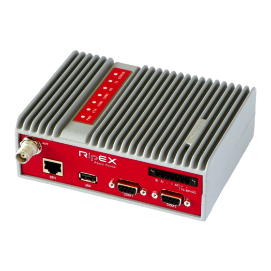
Page 43: Connectors
Fig. 4.6: Antenna connector TNC Note Frequency split (different Rx and Tx frequency) is independent from the presence of two antenna connectors. It can be set even on standard RipEX with one antenna connector. © RACOM s.r.o. – RipEX Radio modem & Router... -
Page 44: Separated Rx And Tx Antennas
−(GND) – for SLEEP IN, HW ALARM INPUT +(POWER) – for HW ALARM OUTPUT HW ALARM OUTPUT +10–30VDC +POWER (10 to 30 V) −10–30VDC −POWER (GND) Pins 3 and 7, 4 and 6 are connected internally. RipEX Radio modem & Router – © RACOM s.r.o. -
Page 45: Supply Connector
If an alarm is triggered, HW ALARM OUTPUT is internally Pin No.: 1 2 3 4 5 6 connected to GND. If the external device requires connection to positive terminal of the power supply, PIN 4 should be used. POWER © RACOM s.r.o. – RipEX Radio modem & Router... -
Page 46: Rj-45F
COM1, 2 – RS232 COM2 – RS485 signal In/ Out signal In/ Out — line B In/Out line A In/Out — — Fig. 4.11: Serial connector — — — — — RipEX Radio modem & Router – © RACOM s.r.o. -
Page 47: Serial Connector
Then the README.txt file, which contains all the necessary information on the structure and names of files and directories, is written into the root directory of the disc. Please follow the detailed instructions in that file. © RACOM s.r.o. – RipEX Radio modem & Router... -
Page 48: Reset Button
NTP server inside RipEX. See Adv. Conf., Time for more. In this case the front panel contains a SMA female 50 ohm connector for connecting the GPS antenna. Fig. 4.14: GPS Connector SMA RipEX Radio modem & Router – © RACOM s.r.o. -
Page 49: Indication Leds
RipEX does not function properly. Maintenance web page is mostly accessible even in Emergency status. If the problem cannot be eliminated after a power cycle, send the unit to RACOM for repair. © RACOM s.r.o. – RipEX Radio modem & Router... -
Page 50: Technical Specification
> 40 dB Spurious Emissions (Conducted) < −36 dBm Radiated Spurious Emissions < −36 dBm Adjacent channel power < −60 dBc Transient adjacent channel power < −60 dBc Receiver Sensitivity Detail RipEX Radio modem & Router – © RACOM s.r.o. - Page 51 50 Ω TNC female LED panel 7× tri-color status LEDs Power, ETH, COM1, COM2, Rx, Tx, Status Enviromental IP Code (Ingress Protection) IP40 MTBF (Mean Time Between Failure) > 100 000 hours © RACOM s.r.o. – RipEX Radio modem & Router...
- Page 52 Trap alarms generation as per settings Real time/Save to file analysis of all physical interfaces (RADIO, ETH, COM1, COM2) and some internal interfaces between Monitoring software modules (e.g. Terminal servers, Modus TCP server etc.) RipEX Radio modem & Router – © RACOM s.r.o.
-
Page 53: Recommended Cables
V03VH-H 1×0,5 Max. 3 m COM1 LiYCY 4×0,14 Max. 3 m COM2 LiYCY 4×0,14 Max. 3 m USB to 10/100 Ethernet Adapter ADE-X5 Max. 3 m STP CAT 5e As needed © RACOM s.r.o. – RipEX Radio modem & Router... -
Page 54: Unlimited 50 Khz
26 dB Bandwidth 20.83 2CPFSK 24K0F1DBN 22.1 30.6 41.67 4CPFSK 24K0F1DDN 23.9 31.7 41.67 DPSK 45K0G1DBN 45.1 51.0 83.33 π/4-DQPSK 45K0G1DDN 44.8 51.0 D8PSK 45K0G1DEN 45.3 51.3 166.67 16DEQAM 45K0D1DEN 44.7 51.0 RipEX Radio modem & Router – © RACOM s.r.o. -
Page 55: Fcc+Ce 50 Khz
26 dB Bandwidth 20.83 2CPFSK 22K7F1DBN 22.7 34.8 41.67 4CPFSK 29K7F1DDN 29.5 38.0 34.72 DPSK 40K0G1DBN 39.3 45.5 96.44 π/4-DQPSK 40K0G1DDN 39.2 45.6 104.16 D8PSK 40K0G1DEN 39.5 44.8 138.89 16DEQAM 40K0D1DEN 39.1 45.1 © RACOM s.r.o. – RipEX Radio modem & Router... -
Page 56: Ce 25 Khz
26 dB Bandwidth 10.42 2CPFSK 13K8F1DBN 13.6 19.4 20.83 4CPFSK 14K2F1DDN 14.3 18.2 20.83 DPSK 24K0G1DBN 23.5 27.1 41.67 π/4-DQPSK 24K0G1DDN 23.9 27.2 62.49 D8PSK 24K0G1DEN 23.5 26.9 83.32 16DEQAM 24K0D1DEN 23.9 27.3 RipEX Radio modem & Router – © RACOM s.r.o. -
Page 57: Ce 12.5 Khz
OBW 99% [kHz] 26 dB Bandwidth 5.21 2CPFSK 7K00F1DBN 10.42 4CPFSK 7K00F1DDN 10.42 DPSK 11K9G1DBN 11.9 13.6 20.84 π/4-DQPSK 11K9G1DDN 11.8 13.6 31.25 D8PSK 11K9G1DEN 11.8 13.4 41.66 16DEQAM 11K9D1DEN 11.8 13.5 © RACOM s.r.o. – RipEX Radio modem & Router... -
Page 58: Ce 6.25 Khz
26 dB Bandwidth 2.61 2CPFSK 3K00F1DBN 2.95 4.35 5.21 4CPFSK 3K00F1DDN 3.17 3.92 5.21 DPSK 6K00G1DBN 5.91 6.71 10.42 π/4-DQPSK 6K00G1DDN 8.94 6.81 15.62 D8PSK 6K00G1DEN 5.93 6.68 20.83 16DEQAM 6K00D1DEN 5.81 6.74 RipEX Radio modem & Router – © RACOM s.r.o. -
Page 59: Fcc 25 Khz
π/4-DQPSK -115 -113 -109 17.36 1.00 π/4-DQPSK -114 -111 -106 19.53 0.75 D8PSK -109 -106 -101 26.04 1.00 D8PSK -107 -104 26.04 0.75 16DEQAM -107 -104 34.72 1.00 16DEQAM -105 -102 © RACOM s.r.o. – RipEX Radio modem & Router... -
Page 60: Fcc 6.25 Khz
FCC 6.25 kHz Tx Classification kbps Modulation Emission OBW 99% [kHz] 26 dB Bandwidth 5.21 4CPFSK 4K35F1D 4.05 5.21 8.68 π/4-DQPSK 5K00G1D 4.89 5.63 13.02 D8PSK 5K00G1D 4.88 5.56 17.36 16DEQAM 5K00G1D 4.87 5.63 RipEX Radio modem & Router – © RACOM s.r.o. -
Page 61: Narrow 25 Khz
The RipEX spurious response rejection is defined as "better than 70 dB", where 70 dB is the limit defined by ETSI EN 300 113. We confirm that the real measured values of this parameter are better than 75 dB. © RACOM s.r.o. – RipEX Radio modem & Router... - Page 62 26 dB, rel- ative to a given and predetermined zero dB level. Please contact RACOM for current status of official test reports for CE, FCC and other standards for different models (frequencies) and different channel spacings.
-
Page 63: Model Offerings
ROUTER – enables Operating mode Router. If not activated, only Bridge mode is available (Part No. RipEX-SW-ROUTER) 166/83 – enables the two highest Data rates for 50 and 25 kHz channel spacings, (Part No. RipEX- SW-166/83) © RACOM s.r.o. – RipEX Radio modem & Router... - Page 64 RipEX_DUMMYLOAD – Dummy load antenna RipEX_FAN_KIT – Fan kit, for external cooling RipEX_C_NM_50 – Feedline cable, RG58, 50 cm, TNC Male – N Male OTH-HX090F/F – Coaxial overvoltage protection 0–1.5 GHz, N female/N female RipEX Radio modem & Router – © RACOM s.r.o.
- Page 65 RipEX-HS – 19" Hot standby chassis, RipEX units excl., pow.supplies incl. (has got its own ordering codes, see RipEX-HS User manual) RipEX-HSB – 19" Battery pack chassis for RipEX-HS, batteries excl. © RACOM s.r.o. – RipEX Radio modem & Router...
-
Page 66: Accessories
Fig. 4.16: RipEX-HS Fig. 4.17: RipeX-HS dimensions For more information see RipEX-HS datasheet or User manual on www.racom.eu ETH/USB adapter ETH/USB adapter for service access to the web interface via USB connector. Includes a built-in DHCP server which provides up to 5 leases. -
Page 67: Wifi Dapter
M!DGE accessories: • Whip antenna (900–2100 MHz, 2.2 dBi, vertical) • Outside dimensions: 455 × 365 × 185 mm • Weight approx. 4 kg (excluding the RipEx’s and M!DGE) Fan kit © RACOM s.r.o. – RipEX Radio modem & Router... -
Page 68: Fan Kit Mounting
Fig. 4.21: Fan kit mounting Fig. 4.22: RipEX with Fan kit L-bracket Installation L bracket for vertical mounting. For details on use see chapter Mounting and chapter Dimensions. Fig. 4.23: L-bracket RipEX Radio modem & Router – © RACOM s.r.o. -
Page 69: Flat Bracket
L - bracket Fig. 4.24: RipEX with L-bracket Flat-bracket Installation bracket for flat mounting. For details on use see chapter Mounting. Fig. 4.25: Flat bracket Flat - bracket Fig. 4.26: RipEX with Flat-bracket © RACOM s.r.o. – RipEX Radio modem & Router... -
Page 70: 19" Rack Shelf
○ 100 – 256 V AC / 24 V DC ○ 230 V AC / 24 V DC ○ 48 V DC / 24 V DC ○ MS2000/12 + back up battery 7.2 Ah Fig. 4.28: 19" Rack shelf RipEX Radio modem & Router – © RACOM s.r.o. -
Page 71: 19" Rack Shelf - Double
○ 100 – 256 V AC / 24 V DC ○ 230 V AC / 24 V DC ○ 48 V DC / 24 V DC ○ MS2000/12 + back up battery 7.2 Ah © RACOM s.r.o. – RipEX Radio modem & Router... - Page 72 Product Fig. 4.30: 19" Rack shelf – double Fig. 4.31: 19" Rack shelf–double – dimensions RipEX Radio modem & Router – © RACOM s.r.o.
-
Page 73: Dummy Load
(RipEX side) and N Male connectors on the ends. It is intended for use between RipEX and cab- inet panel. 12. Others For other accessories (Power supplies, Antennas, Coaxial overvoltage protection etc.) kindly visit http://www.racom.eu/eng/products/radio-modem-ripex.html#accessories © RACOM s.r.o. – RipEX Radio modem & Router... -
Page 74: Bench Test
You’ll find the description of the individual LED states in Section 4.3, “Indication LEDs”. 5.3. Connecting RipEX to a programming PC To configure a RipEX you can connect it to your PC in three ways: RipEX Radio modem & Router – © RACOM s.r.o. - Page 75 The RipEX’s IP address for access over the ETH/USB adapter is fixed: 10.9.8.7. Go to 4 Login to RipEX PC connected directly to ETH port Set a static IP address in PC, example for Windows XP: © RACOM s.r.o. – RipEX Radio modem & Router...
- Page 76 192.168.169.169 – when connected directly to ETH Note https - For security reasons the http protocol with ssl encryption can be used for the communication between the PC and RipEX. The https protocol requires a security RipEX Radio modem & Router – © RACOM s.r.o.
-
Page 77: Status Menu
The certificate is signed by the certification authority Racom s.r.o. It meets all security regulations and you need not be concerned about importing it into your computer. Confirm the import with all warnings and exceptions that your browser may display during installation. -
Page 78: Basic Setup
If the radio communication between RipEX’s is functional, you can proceed with a test of communication between the connected devices. You can monitor the status of configuration using the diodes on the LED panel, see Section 4.3, “Indic- ation LEDs”. http://www.racom.eu/eng/products/m/ripex/app/routing.html RipEX Radio modem & Router – © RACOM s.r.o. -
Page 79: Installation
Fig. 6.1: Flat lengthwise mounting to DIN rail – recommended Fig. 6.2: Flat widthwise mounting to DIN rail For vertical mounting to DIN rail, L-bracket (optional accessory) is used. © RACOM s.r.o. – RipEX Radio modem & Router... -
Page 80: Vertical Lengthwise Mounting To Din Rail
For flat mounting directly to the support you must use the Flat bracket (an optional accessory). Fig. 6.5: Flat mounting using Flat bracket Fig. 6.6: Vertical lengthwise mounting to DIN rail For more information see Section 4.6, “Accessories” – Flat-bracket. RipEX Radio modem & Router – © RACOM s.r.o. -
Page 81: Rack Shelf
(recommended) or it can run permanently (it should be connected in parallel to the RipEX’s power supply). Configuration of the Alarm Output is described in chapter Advanced Configuration, Device. For more information see Section 4.6, “Accessories” – Fan kit. © RACOM s.r.o. – RipEX Radio modem & Router... -
Page 82: Antenna Mounting
The antenna feed line should be chosen so that its attenuation does not exceed 3 to 6 dB as a rule of thumb, see Chapter 3, Network planning. Use 50 Ω impedance cables only. RipEX Radio modem & Router – © RACOM s.r.o. -
Page 83: Grounding
EMC standards. Never install a power supply 10 – 30VDC close to the antenna. Maximal supply cable length is 3 m. +10 to +30 V Fig. 6.11: 10–30 VDC Supplying © RACOM s.r.o. – RipEX Radio modem & Router... -
Page 84: Advanced Configuration
The Unit name (Settings/Device/Unit name) of the RipEX from which data is currently displayed and which is currently managed. Remote IP address of the remotely connected RipEX. After filling-in the Connect button shall be pressed. RipEX Radio modem & Router – © RACOM s.r.o. -
Page 85: Status
On-line help for each individual item is provided by balloon tips (when cursor is placed over an item name). When an item goes red, it means that the item is monitored for alarm and its value is in the alarm range (see Settings/Device/Alarm management) © RACOM s.r.o. – RipEX Radio modem & Router... -
Page 86: Settings
$ (Dollar symbol) ; (Semicolon) Important Unit name is solely for the user's convenience, no DNS (Domain Name Server) is used in the RipEX network. Operating Mode List box: Bridge, Router RipEX Radio modem & Router – © RACOM s.r.o. - Page 87 Furthemore, a copy of every frame transmitted to or received from the Radio channel is stored (for a period). Whenever a duplicate of a stored frame is received, it is discarded to avoid possible © RACOM s.r.o. – RipEX Radio modem & Router...
- Page 88 RipEX, using the very short service packet (ACK), in order to indicate that it has received the packet successfully. If ACK is not received, RipEX will retransmit the packet according its setting of Retries. RipEX Radio modem & Router – © RACOM s.r.o.
- Page 89 (RTU's) would reply more or less in the same instant. In order to prevent such a collision, the TX delay should be set individually in each slave RipEX. The length of responding packet has to be taken into account. © RACOM s.r.o. – RipEX Radio modem & Router...
- Page 90 RipEX ”B“, even if “A” doesn't have any alarm and uses “B” for a set time in order to confirm that RipEX ”B“ is fully ready-to-operate. ○ Start Date [YYYY-MM-DD] Fill in the Date in the required format when Auto Toggle mode starts. RipEX Radio modem & Router – © RACOM s.r.o.
- Page 91 ■ NTP server – The source of time is a standard NTP server. This server can be connected either via the Ethernet interface or over the Radio channel (any RipEX runs automatically as a NTP server). © RACOM s.r.o. – RipEX Radio modem & Router...
- Page 92 (Settings/Device/Alarm management or Routing/Backup). • Community name Default = public This string is used for authentication with SNMP manager. Max. length is 32 chars. Following characters are not allowed: " (Double quote) RipEX Radio modem & Router – © RACOM s.r.o.
- Page 93 L3 Firewall to Off, sets ARP proxy&VLAN settings to Off and Ethernet speed to Auto. L3 Firewall settings do not impact packets received and redirected from/to Radio channel. • MAC (L2) © RACOM s.r.o. – RipEX Radio modem & Router...
- Page 94 Ucc, Temp – approx. 10 sec. after booting PWR, VSWR - approx. 10 sec. after booting and after the first transmission Others – approx. 200 sec. of respective communication • Threshold List box: Default, Manual, RipEX Radio modem & Router – © RACOM s.r.o.
- Page 95 Detail Graphs are ticked in the Unit ready line, the respective action is taken after every Hardware Alarm Output state change (and also when the Apply button is activated after a reconfiguration). © RACOM s.r.o. – RipEX Radio modem & Router...
- Page 96 Default = 300 (min. 60, max. 64800) RipEX stays ACTIVE for the set time from the moment of its wake-up. When this timeout expires, the RipEX switches back to the SAVE state. RipEX Radio modem & Router – © RACOM s.r.o.
- Page 97 SSIDs make sure that data gets sent to the correct destination. If empty, default value is filled. ○ IEEE standard There are different standards used for WiFi networks. RipEX supports some of them. List box: possible values Default = 802.11g © RACOM s.r.o. – RipEX Radio modem & Router...
- Page 98 RipEX periodically broadcasts its Watched values to neighbouring units. The Watched values can be displayed in Graphs and Neighbours menu. Note: When Bridge mode is used, watched values broadcasting creates collisions for user traffic. Be careful in using this feature. RipEX Radio modem & Router – © RACOM s.r.o.
- Page 99 Detail graph file is stored in case of that alarm. Twenty samples prior the alarm event and forty samples after the alarm event are recorded. When another alarm occurs while a Detail graph file is opened, the sampling continues normally and no other file is opened. © RACOM s.r.o. – RipEX Radio modem & Router...
-
Page 100: Menu Radio
Default = HTTP+HTTPS Required protocol for configuration web page is set here. If “Off”, configuration web pages are inaccessible. For HTTPS either RACOM (default) or your own SSL certificate can be used. ○ HTTP Port Default = 80 Just for information, can not be changed. - Page 101 RipEX allows multiple settings of modulation parameters for every channel spacing to enable meeting the different regulations which apply in different countries. Naturally different limits on transmitted signal parameters result in different Modulation rates. © RACOM s.r.o. – RipEX Radio modem & Router...
- Page 102 The lower the FEC ratio, the better the capability of error correction and the lower the user data rate. The User data rate = Modulation rate x FEC ratio. Optimization* List box: On, Off RipEX Radio modem & Router – © RACOM s.r.o.
- Page 103 Unit) set, the RipEX router performs standard IP fragmentation. A packet longer than the configured size is split into the needed number of fragments, which are then independently transmitted - the first © RACOM s.r.o. – RipEX Radio modem & Router...
-
Page 104: Menu Ethernet
When Operating mode is set to Bridge, it is the default gateway (applies to whole RipEX). When Oper- ating mode is set to Router, it is not displayed here. Default GW can be set only in the Routing menu. DHCP* List box: Off, Server Default = Off RipEX Radio modem & Router – © RACOM s.r.o. - Page 105 Modbus TCP* Use this setttings only for Modbus TCP Master when it communicates with both types of Modbus slaves using either Modbus RTU or Modbus TCP protocols. Or when TCP/IP communication should © RACOM s.r.o. – RipEX Radio modem & Router...
- Page 106 − SCADA devices on all sites have to be connected to the same interface (COM1 or COM2) − only one SCADA device to one COM port can be connected, even if the RS485 interface is used ■ Base IP Default = IP address of ETH interface http://www.racom.eu/eng/products/m/ripex/app/modbus.html RipEX Radio modem & Router – © RACOM s.r.o.
- Page 107 You may tick/untick each translation line in order to make it active/not active. ■ Modify Delete and Add buttons allow to add or to delete a line. The lines can be sorted using up and down arrows. © RACOM s.r.o. – RipEX Radio modem & Router...
- Page 108 Protocol follows the same principles as a protocol on COM interface. You may tick/untick each in- dividual Terminal server in order to make it active/inactive. Note: Max. user data length in a single datagram processed by the Terminal server is 8192 Bytes. http://www.racom.eu/eng/products/m/ripex/app/modbus.html RipEX Radio modem & Router – © RACOM s.r.o.
- Page 109 You may tick/untick each line in order to make it active/not active. • Modify Delete and Add buttons allow to add or to delete a line. The lines can be sorted using up and down arrows. © RACOM s.r.o. – RipEX Radio modem & Router...
- Page 110 List box: On, Off Default = Off To create Subnet click on Add Subnet. The new Subnet line appears. Fill in IP/MASK. Unlimited number of virtual Ethernet interfaces (Alias IP addresses) can be set. RipEX Radio modem & Router – © RACOM s.r.o.
- Page 111 You may tick/untick each line in order to make it active/not active. VLAN is active when at least one of its subnets is active (even the first line can be inactive). © RACOM s.r.o. – RipEX Radio modem & Router...
-
Page 112: Menu Com
The settings of Data rate, Data bits, Parity and Stop bits of COM port and connected device must match. Baud rate [bps] List box: standard series of rates from 300 to 115200 bps RipEX Radio modem & Router – © RACOM s.r.o. - Page 113 MTU, it is recommended to use values in 200 – 400 bytes range. This MRU and the MTU in Radio settings are independent. However MTU should be greater or equal to MRU. © RACOM s.r.o. – RipEX Radio modem & Router...
- Page 114 SCADA serial packets to UDP datagrams. The Address translation settings are used to define the destination IP address and UDP port. Then these UDP datagrams are sent to RipEX router, processed RipEX Radio modem & Router – © RACOM s.r.o.
- Page 115 SCADA protocol to SCADA protocol, so this is one of the main reasons why an individual Protocol utility in RipEX for each SCADA protocol has to be used. ○ Broadcast © RACOM s.r.o. – RipEX Radio modem & Router...
- Page 116 The Address translation is defined in a table. There are no limitations such as when the Mask translation is used. If there are more SCADA units on RS485 interface, their “Protocol ad- RipEX Radio modem & Router – © RACOM s.r.o.
- Page 117 COM1(2) or from a Terminal server 1-5 are sent without any processing transparently to Radio channel to set IP destination and UDP port. Received frames from Radio channel are sent to COM1 or COM2 or Terminal server 1-5 according UDP port settings. © RACOM s.r.o. – RipEX Radio modem & Router...
- Page 118 When a RipEX radio network runs in the Router mode, multiple Cactus Masters can be used within one Radio network and one Slave can be polled by more than one Master. RipEX Radio modem & Router – © RACOM s.r.o.
- Page 119 • Block control mode List box: BCC, CRC Default = BCC According to the DF1 specification, either BCC or CRC for Block control mode (data integrity) can be used. • Broadcast © RACOM s.r.o. – RipEX Radio modem & Router...
- Page 120 Broadcast - only On, Off. Protocol broadcast address is not configurable, it is defined by Address mode in Advance parameter (default 0xFF) Address translation Table Mask Slave Broadcast accept • Advanced parameters RipEX Radio modem & Router – © RACOM s.r.o.
- Page 121 Since the ITT Flygt protocol Master (centre) polls the Slaves (remotes) one by one without any addressing, number of slaves has to be defined. Address translation Table Mask Slave Broadcast accept © RACOM s.r.o. – RipEX Radio modem & Router...
- Page 122 When a RipEX radio network runs in the Router mode, multiple RP570 Masters can be used within one Radio network and one Slave can be polled by more than one Master. Underlined parameters are described in Common parameters. Mode Connected device RipEX Radio modem & Router – © RACOM s.r.o.
- Page 123 RB Response timeout. When the RipEX does not receive the response(s) from the RP570 slave, the RipEX does not respond to the RB packet from the Master which it receives over the Radio channel. • RB Request period [ms] © RACOM s.r.o. – RipEX Radio modem & Router...
- Page 124 Specify the sequence number of the byte, where the Protocol address starts. Note 1: 3964(R) protocol is using escape sequence (control sequence) for DLE(0x10). I.e. when 0x10 is in user data, 0x1010 is sent instead. RipEX Radio modem & Router – © RACOM s.r.o.
- Page 125 . SLIP modifies a standard IP packet by prepending and appending a special SLIP END character to it, which allows packets to be distinguished as separate. SLIP requires a COM http://dictionary.reference.com/browse/Internet%20Protocol http://dictionary.reference.com/browse/Ethernet http://dictionary.reference.com/browse/serial%20line © RACOM s.r.o. – RipEX Radio modem & Router...
- Page 126 This subnet can not overlap with any other subnet in RipEX defined on Radio, ETH or VLAN. UNI is the "Universal" protocol utility designed by RACOM. It is supposed to be used when the applic- ation protocol is not in the RipEX list and the addressed mode of communication is preferable in the network (which is a typical scenario).
- Page 127 E.g. spontaneous packets to be generated at remote sites. This mode is suitable for Master-Master communication scheme or a com- bination of the UNI and ASYNC LINK protocols. Broadcast Address translation Table Mask Slave Broadcast accept © RACOM s.r.o. – RipEX Radio modem & Router...
-
Page 128: Routing
Ethernet. All devices which should be accessible directly have to be within the same LAN. If Subnets (Aliases) or VLAN’s are defined (menu Settings/Device/ARP proxy & VLAN) you can see them by clicking on VLAN & Subnets on the right side. RipEX Radio modem & Router – © RACOM s.r.o. - Page 129 Gateway is set to 0.0.0.0 and Backup is set to Off. The other lines keep their settings even when not- active. Modify Delete and Add buttons allow to delete or add a line. One may order the lines using up and down arrows. © RACOM s.r.o. – RipEX Radio modem & Router...
- Page 130 Default = 60 sec, [Max=3600] When the set period expires, the next Hello packet is transmitted. To avoid the collisions, there is a jitter of approx. 5%. ○ Hello packet success rate [%] RipEX Radio modem & Router – © RACOM s.r.o.
- Page 131 Find - finds (highlights the respective line in the table) the route for a specific IP address if exists. • Check routing - highlights duplicate routes for specific IP if they exist. • Backup status - refresh the status of backup routes (Good, Failure, Unknown, Currently used) © RACOM s.r.o. – RipEX Radio modem & Router...
-
Page 132: Diagnostic
Note: Remember that both Neighbours and Statistic logs are cleared. Display button – displays values of the Difference log, i.e. the values accumulated from time when the Set button has been pressed. RipEX Radio modem & Router – © RACOM s.r.o. - Page 133 Graphs • green background indicates, that the item is monitored for alarm and its average value is within the “normal” range (Settings/Device/Alarm management) © RACOM s.r.o. – RipEX Radio modem & Router...
- Page 134 Voltage Standing Wave Ratio (1.0=best, 1.0–1.8=acceptable, >2.5=indicates a serious problem in antenna or feeder) ○ Packets [Rx/Tx] The total number of packets received from / transmitted to ETH, COM1, COM2 interfaces. Can be used for interface activity diagnostic. RipEX Radio modem & Router – © RACOM s.r.o.
-
Page 135: Menu Statistic
IP addresses of RipEXes who transport them. ETH Protocol packets for TCP proxy are counted on "TCP socket", i.e. between RipEX Ethernet and Host device. Rx from Host device to RipEX, Tx from RipEX to Host. © RACOM s.r.o. – RipEX Radio modem & Router... -
Page 136: Menu Graphs
There is a list of files, which are saved in RipEX and which can be displayed. Date and time corres- ponds with the start of the file. • 1st IP List box: possible values Default = This unit RipEX Radio modem & Router – © RACOM s.r.o. - Page 137 Start/Stop - only for Detail graph. Active (displayed on the screen) when Detail Graph start (to be set in Settings/Graphs) is set to Single. Start button activates the sampling. Stop button can close the file before 60 samples are saved. © RACOM s.r.o. – RipEX Radio modem & Router...
-
Page 138: Menu Ping
Ping utility generates on-line report each 2 seconds while you are connected to Local unit and each 10 sec. while it is generated from Remote unit and it is transffered over Radio channel. RipEX Radio modem & Router – © RACOM s.r.o. - Page 139 The length of user data, the range from 8 to 4096 Byte. Some overhead to this Length is always added like these: ICMP - 28 bytes RSS - 43 bytes for IP+UDP+RACOM header + 8 bytes (Trace-RSS and DQ) per each radio hop + 4 bytes (marking in server) RSS ping can not be longer than 3/4 MTU.
- Page 140 :56/209[RSS/DQ]-->10.10.10.243:51/225[RSS/DQ]-- >192.168.131.243" "192.168.131.243-->10.10.10.242 :46/214[RSS/DQ]-->10.10.10.241 :57/213[RSS/DQ]-- >10.10.10.241" 131 bytes = RSS packet size (RACOM header + data + trace) 10.10.10.242 = repeater IP 192.168.131.243 = destination IP seq = ping sequence number rtt = round trip time, the time from transmission to reception •...
- Page 141 Monitoring is an advanced on-line diagnostic tool, which enables a detailed analysis of communication over any of the interfaces of a RipEX router. In addition to all the physical interfaces (RADIO, ETH, © RACOM s.r.o. – RipEX Radio modem & Router...
- Page 142 ■ Filter parameters for IP/ARP packets (available for RADIO, ETH and Internal RADIO (router), COMn(router), TSn(router), Modbus TCP(router), TCP proxy (TCP), TCP proxy(router)): ○ IP src IP source address range in the following format: aaa.bbb.ccc.ddd/mask RipEX Radio modem & Router – © RACOM s.r.o.
- Page 143 Radio IP address of this RipEX unit and broadcast frames are processed further by monitoring filters. • On – all frames detected on the Radio channel are passed to monitoring filters ○ Link Control Frames © RACOM s.r.o. – RipEX Radio modem & Router...
- Page 144 ETH interface on this web page. Note: Not all general rules are supported. When unsupported or wrong syntaxes are used, the warning (ETH monitoring terminated. Invalid tcpdump parameters?) will be displayed. RipEX Radio modem & Router – © RACOM s.r.o.
- Page 145 Apply button when the monitoring is running, i.e. when the respective Start (File Start) button has been gray. Clicking the Apply button enforces the configuration change (e.g. adding one more interface) to the running monitoring process ■ Internal interfaces description © RACOM s.r.o. – RipEX Radio modem & Router...
- Page 146 ○ RL header CRC error "RL-header" is Radio Link protocol header. Displayed while "RADIO" (Rx) interface is being monitored as part of a packet header. ○ Bridge stream datablock header CRC error RipEX Radio modem & Router – © RACOM s.r.o.
- Page 147 Displayed while "RADIO" (Tx) interface is being monitored as part of a packet header. ○ RF interface not ready - high radio board temperature! The transmitting is blocked because radio board has reached a temperature higher than 95 °C. © RACOM s.r.o. – RipEX Radio modem & Router...
- Page 148 ○ Router mode frame The frame in "Router" format has been received, but Operating mode is set to Bridge. Displayed while "RADIO" (Rx) interface is being monitored as part of a packet header. RipEX Radio modem & Router – © RACOM s.r.o.
-
Page 149: Maintenance
Master key. There are two ways to input the SW key into RipEX: Fill in the key you have received from RACOM or your distributor in the Key box using copy/paste or the SW key can be uploaded from a file. Fill in the SW Key file, or browse your disk in order to find the file. -
Page 150: Menu Maintenance Configuration
– “Active” and “Archive”. Unit is always using the Active version. The Archive version is there just for convenience and safety of firmware manipulations. It can also be uploaded to a remote unit over the Radio channel. RipEX Radio modem & Router – © RACOM s.r.o. -
Page 151: Menu Maintenance Password
Note: New firmware as well as SW feature keys can be uploaded directly from a USB flash disk. Only FAT32 file system on flash disk is supported. Download firmware file from www.racom.eu. Save this file without any change (name) in the root directory of USB flash. When SW key(s) will be uploaded, save the respective file(s) also in the root directory with the file name(s) unchanged. - Page 152 Apply – when pressed, the uploaded certificate is activated. Afterwards the unit automatically reboots itself. • Default – when pressed, the default RACOM SSL certificate is uploaded. To be activated, Apply button has to be executed. 7.6.7. RF transmission test It is intended to be used for laboratory measurements or antenna testing.
-
Page 153: Menu Maintenance Configuration
Fig. 7.20: Menu Maintenance Configuration Technical support package is the file where some internal events are recorded. It can be used by RACOM technical support when a deeper diagnostic is required. The most recent part of it can be downloaded to the local PC. -
Page 154: Cli Configuration
Keys are unique for each individual RipEX Serial number. Private key is downloaded in RipEX, for public key kindly contact RACOM and provide RipEX S/N. Connecting with a putty client. Type the following command into the window Host Name (or IP address): admin@192.168.169.169... -
Page 155: Troubleshooting
All RipEX’s share the default IP address but their MAC addresses are different, meaning this record interferes with your purpose. The timeout for automatic cache clearing may be longer so you can delete the entry manually by typing: © RACOM s.r.o. – RipEX Radio modem & Router... - Page 156 (e.g. cars in front of the antenna), shifting reflective areas etc. If you cannot remove the cause of disturbances, you will need to ensure signal is strong enough to cope with it. RipEX Radio modem & Router – © RACOM s.r.o.
-
Page 157: Safety, Environment, Licensing
Antenna Gain G Gain G General Population General Population Antenna description code [dBi] [–] / Uncontrolled Ex- / Controlled Expos- posure [cm] ure [cm] OV160.1 single dipole OV160.2 stacked double dipole © RACOM s.r.o. – RipEX Radio modem & Router... - Page 158 [dBi] [–] / Uncontrolled Ex- / Controlled Expos- posure [cm] ure [cm] OV160.1 single dipole OV160.2 stacked double dipole SA160.3 5 element directional Yagi SA160.5 9 element directional Yagi 12.5 17.8 RipEX Radio modem & Router – © RACOM s.r.o.
-
Page 159: Minimum Safety Distance 300-400 Mhz
Antenna description code [dBi] [–] / Uncontrolled Ex- / Controlled Expos- posure [cm] ure [cm] OV380.1 single dipole OV380.2 stacked double dipole SA380.3 3 element directional Yagi SA380.5 5 element directional Yagi © RACOM s.r.o. – RipEX Radio modem & Router... - Page 160 Antenna Gain G Gain G General Population General Population Antenna description code [dBi] [–] / Uncontrolled Ex- / Controlled Expos- posure [cm] ure [cm] OV380.1 single dipole OV380.2 stacked double dipole RipEX Radio modem & Router – © RACOM s.r.o.
-
Page 161: High Temperature
Under the Directive, used equipment must be marked, collected separately, and disposed of properly. Racom has instigated a programme to manage the reuse, recycling, and recovery of waste in an envir- onmentally safe manner using processes that comply with the WEEE Directive (EU Waste Electrical and Electronic Equipment 2002/96/EC). -
Page 162: Important Notifications
Only undermentioned manufacturer is entitled to repair any devices. 10.6. Important Notifications Sole owner of all rights to this operating manual is the company RACOM s. r. o. (further in this manual referred to under the abbreviated name RACOM). All rights reserved. Drawing written, printed or repro- duced copies of this manual or records on various media or translation of any part of this manual to foreign languages (without written consent of the rights owner) is prohibited. -
Page 163: Product Conformity
University of California, Berkeley and its contributors. 10.7. Product Conformity RACOM declares that the RipEX radio modem & router is in conformity with the es- sential requirements and other relevant requirements of the Directive of the European Parliament and of the Council 1999/5/EC on radio equipment and telecommunications terminal equipment and the mutual recognition of their conformity. -
Page 164: Declaration Of Conformity Ripex
Nove Mesto na Morave, 2 of April 2013 Jiri Hruska, CEO RACOM s.r.o. • Mirova 1283 • 592 31 Nove Mesto na Morave • Czech Republic www.racom.eu Tel.: +420 565 659 511 • Fax: +420 565 659 512 • E-mail: racom@racom.eu Fig. -
Page 165: Warranty
The serviced equipment shall be returned by RACOM to the customer by prepaid freight. If circumstances do not permit the equipment to be returned to RACOM, then the customer is liable and agrees to reim- burse RACOM for expenses incurred by RACOM during servicing the equipment on site. When equipment does not qualify for servicing under warranty, RACOM shall charge the customer and be reimbursed for costs incurred for parts and labour at prevailing rates. -
Page 166: Oid Mappings
OID mappings Appendix A. OID mappings "MIB tables", and whole file "OID mappings" can be downloaded from: http://www.racom.eu/eng/products/radio-modem-ripex.html#download More details are described in Application note: See RipEX App notes, SNMP http://hnilux.racom.cz:3004/eng/products/radio-modem-ripex.html#download http://www.racom.eu/eng/products/m/ripex/app/snmp.html RipEX Radio modem & Router – © RACOM s.r.o. -
Page 167: Abbreviations
Hypertext Transfer Protocol Secure Receiver Internet Protocol SCADA Supervisory control and data acquisition kbps kilobit per second Software Defined Radio Local Area Network SNMP Simple Network Management Protocol Line-of-sight Media Access Control © RACOM s.r.o. – RipEX Radio modem & Router... - Page 168 Abbreviations Transmission Control Protocol Terminal server 5 Transmitter User Datagram Protocol VSWR Voltage Standing Wave Ratio WEEE Waste Electrical and Electronic Equipment RipEX Radio modem & Router – © RACOM s.r.o.
-
Page 169: Index
85 parameters, 8, 75 MIB tables, 166 setting, 48, 150 Modbus TCP, 105 demo case, 67 model diagnostic, 26 offerings, 63 dimensions, 40 monitoring menu, 141 mounting bracket, 68, 79 © RACOM s.r.o. – RipEX Radio modem & Router... - Page 170 RipEX, 10 RipEX Hot Stanby, 66 RoHS and WEEE, 161 router, 19, 88, 128 routing table, 128 safety, 157 distance, 157 SCADA, 24 sensitivity, 53 sleep, 45, 51 SNMPl, 92 standards, 12 RipEX Radio modem & Router – © RACOM s.r.o.
-
Page 171: Revision History
Added information about new features: 50 kHz channel spacing, Wifi management, L2 firewall, Flash disc – unit configuration, ssl certificate. Upgraded chapters: Getting started, Key Features, RipEX in detail, Product, Bench test, Technical specification, Model offerings, Accessories, Advanced Configuration © RACOM s.r.o. – RipEX Radio modem & Router...
Need help?
Do you have a question about the RipEX 1.6.0 and is the answer not in the manual?
Questions and answers