
Related Manuals for Schmalz FMHD


Summary of Contents for Schmalz FMHD
- Page 1 Innovative Vacuum for Automation Instruction Manual Vacuum area gripper FMHD 30.30.01.01648/06 | 02.2022 www.schmalz.com...
- Page 2 © J. Schmalz GmbH, 02.2022 This document is protected by copyright. J. Schmalz GmbH retains the rights established thereby. Re- production of the contents, in full or in part, is only permitted within the limits of the legal provisions of copyright law.
-
Page 3: Table Of Contents
LED Display with Impulse Valve ..................31 Operation ......................32 General notes ........................32 Control of FMHD......................35 Sequential Diagram for FMHD with Separating Cylinder and “Blow off” Function ..35 6.2.1 6.2.2 Sequential Diagram for the FMHD with Separating and Ventilation Cylinders ....36 6.2.3... - Page 4 Pneumatic Circuit Diagram................56 Pneumatic Circuit Diagram of the Standard Version FMHD ...........56 Pneumatic Circuit Diagram of the FMHD with Ventilation Cylinder ........57 Pneumatic Circuit Diagram of the FMHD with Impulse Valve .........58 Pneumatic Circuit Diagram of the FMHD – Parallel Circuit ..........59 Other Applicable Documents................
-
Page 5: Safety Instructions
This warning informs the user of a risk that could result in damage to property if it is not avoided. ATTENTION Type and source of danger Consequence ► Remedial action General notes This symbol is used when important notes and information regarding the use of the machine/the sys- tem/the device are provided. Note/information 30.30.01.01648/06 www.schmalz.com EN | 5... -
Page 6: Prohibition Signs
Explanation of the mandatory symbols used in the operating instructions. Icon Description Icon Description Observe the instructions Wear eye protection Use protective footwear Activate prior to maintenance or repair Wear protective gloves Wear a mask Use ear protectors 6 | EN www.schmalz.com 30.30.01.01648/06... -
Page 7: General Safety Instructions
► This instruction manual is specific to the items included in delivery from Schmalz. These operating instructions do not take into account any modifica- tions to the system made by the customer. ► The system may only be connected and operations started once the instruction manual has been read and understood. -
Page 8: Intended Use
The product key/gripper type or part number and year of construction are important for identifying the device. They must always be specified when ordering replacement parts, making warranty claims or making other inquiries about the device. 8 | EN www.schmalz.com 30.30.01.01648/06... -
Page 9: Product Key
Product Key Schmalz will be happy to advise you on selecting a gripper in order to be able to offer the best solution for your application. The product key for configurable vacuum area grippers is made up as follows: Example:... -
Page 10: Product Description
Max. acceleration in vertical direction: 2 m/s². Only switch on suction when the gripper is placed on the workpiece. It is not possible to provide additional suction or pick up other products later. 10 | EN www.schmalz.com 30.30.01.01648/06... -
Page 11: Design Description
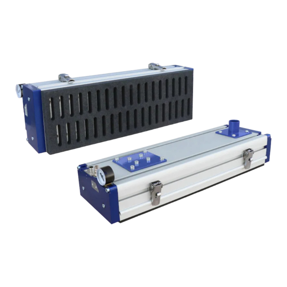
Design Description Vacuum reservoir Valve cham- Fig. Vacuum area gripper FMHD cross-section End cover with function modules Separating cylinder assembly unit Connection pieces for external vacuum generation Base section T-slot with quick-release clamps End cover without function modules Valve section with adhesive valve film... - Page 12 Design of the vacuum area gripper with enhanced functions Fig. Vacuum area gripper FMHD with ejector SBPL and adapter cable for controlling the gripper and ejector Fig. Vacuum area gripper FMHD with ventilation cylinder, widely used quick-change plate and adapter cable with Harting plug Compressed air connection...
- Page 13 1.2 Compressed Air Connection for Flat Suction Cup The compressed air is connected via a 1/4" plug nipple DN7.2 with male thread. Recommended hose diameter is at least 9 mm. It can also be connected using a plug-in screw union. 30.30.01.01648/06 www.schmalz.com EN | 13...
- Page 14 The separating cylinder is single-acting and is pneumatically operated. This unit can be easily removed from the gripper in order to check the seals or the contamination level of the gripper. 14 | EN www.schmalz.com 30.30.01.01648/06...
- Page 15 D Main Body FMHD The main body consists of a length-adjustable extrusion-molded aluminum section. Configurable vac- uum area grippers have a length between 350 mm and 3,500 mm. On the underside of the section there is a glued-in sealing gasket on the right and left.
- Page 16 If the grippers are used in dirty environments or used to transport dirty/wet workpieces, we recommend regularly removing and cleaning or drying the sealing plate. Downtime can be reduced by using a second 16 | EN www.schmalz.com 30.30.01.01648/06...
- Page 17 (2.1) and four screws (2.2). The separating cylinder (2.3) that is mounted on the base plate connects and separates the reservoir chambers and valve chambers to and from one another. The separating cylinder is single-acting and is pneumatically operated. This unit can be removed from the gripper for maintenance. 30.30.01.01648/06 www.schmalz.com EN | 17...
- Page 18 Screws for mounting the cylinder (not shown) Sealing plate Sealing plate sealing Mounting plate sealing Plug-in screw union (compressed air connection) Quick exhaust valve (ensure that they are properly connected) 2.10 Y piece (exhaust) 2.11 Exhaust connection 2.12 Compressed air connection 18 | EN www.schmalz.com 30.30.01.01648/06...
- Page 19 2.1 Ejector silencer – must not be closed 2.2 Vacuum ejector SBPL 2.3 Compressed air connection for vacuum ejector 2.4 Dust filter 2.5 End cover with G1-1/4" connection thread 2.6 Form seal for housing cover 30.30.01.01648/06 www.schmalz.com EN | 19...
-
Page 20: Technical Data
At a vacuum of –0.3 bar, the vacuum generator must provide the specified suction flow rate (at the vacuum connection pieces of the FMHD). Calculated at -300 mbar and full-surface occupancy; vacuum -0.3 bar; actual suction force depending on the product to be gripped. - Page 21 FMHD CV1 1050 2R28 O20 C152L P S60 126 V1 CA1 Extra wide gripper FMHD 250 CV 1 1050 2R28 O20 C138L P S60 126 V1 Gripper with 3R22 grid FMHD CV2 1050 3R22 O20 C152L P S60 126 V1 CA1 Dimensions 111.6...
-
Page 22: Transport And Mounting
Terms and Conditions of Sale and Delivery. 4.1.3 Reporting Damage After delivery of the shipment, damage due to faulty packaging or transport must be reported immedi- ately to the carrier and J.Schmalz GmbH. 22 | EN www.schmalz.com... -
Page 23: Packaging
The system must be stored in its original packaging as long as it is not being used and is to be stored for any period of time. ATTENTION Incorrect storage of the system Material damage to the system ► The system may only be stored as described in the instruction manual. 30.30.01.01648/06 www.schmalz.com EN | 23... -
Page 24: Start Of Operations And Setup
Moisture Very wet workpieces can permanently impair the function of the gripper ► Only grip dry workpieces if possible ► Regularly clean and, if necessary, dry the gripper 24 | EN www.schmalz.com 30.30.01.01648/06... - Page 25 ► Only set workpieces down on clear, even surfaces due to the danger of slip- ping. ► Do not release the load until it rests completely and safely on a secure surface. ► Do not come close to the load when releasing/depositing it and do not touch it. 30.30.01.01648/06 www.schmalz.com EN | 25...
- Page 26 Danger of falling objects/gravity Danger to life and limb ► See general safety notes on the start of operations ► Never stand under suspended loads. Human error Danger to life and limb ► Adhere to the instruction manual 26 | EN www.schmalz.com 30.30.01.01648/06...
-
Page 27: Vacuum Area Grippers
The maximum overpressure in the gripper during “blow off” (vacuum reservoir or valve chamber) must be limited to a maximum of 0.2 bar. Ventilation The opening for ventilating the control valve may not be closed. 30.30.01.01648/06 www.schmalz.com EN | 27... -
Page 28: Vacuum Connection
It can be replaced 1:1 in the existing system with an adapter cable and additional mechanical conversion measures. To do so, you attach the vacuum area gripper FMHD to the existing flange using the supplied washers. Connect the compressed air coupling and Harting plug in the same way as before. The adapter cable is designed to ensure the control unit does not have to be modified. -
Page 29: Electrical Connections
► The system must incorporate a safe electrical cut-off of the power supply in compliance with EN 60204. ► Do not connect or disconnect the plug connectors when live. ► Only operate the system with protected extra-low voltage. Observe the separate instruction manual when connecting the vacuum generator. 30.30.01.01648/06 www.schmalz.com EN | 29... - Page 30 When using an FMHD with an adapter set, the pin assignments for the Harding plug correspond to those of the SBX. It is therefore not necessary to adapt the system control unit to the FMHD. Plug for the adapter set SBX...
-
Page 31: Led Display In The Standard Version
Separating cylinder “Extend cylinder ON” LED not illuminated (reservoir and valve chamber separated – suction not applied) “Blow off/vent ON” LED illuminated (depositing the workpiece) Blow off/ ventilation cylinder “Blow off/vent OFF” LED not illuminated 30.30.01.01648/06 www.schmalz.com EN | 31... -
Page 32: Operation
Moisture Very wet workpieces can permanently impair the function of the gripper ► Only grip dry workpieces if possible ► Clean the gripper regularly and dry the foam if necessary 32 | EN www.schmalz.com 30.30.01.01648/06... - Page 33 ► Only set workpieces down on clear, even surfaces due to the danger of slip- ping. ► Do not release the load until it rests completely and safely on a secure surface. ► Do not come close to the load when releasing/depositing it and do not touch it. 30.30.01.01648/06 www.schmalz.com EN | 33...
- Page 34 Consult the manufacturer before operating it at ambient temperatures higher or lower than the permitted temperatures. The system can only achieve its maximum lift capacity if it is completely covered by an airtight work- piece. For the maximum permitted load, see the Technical Data. 34 | EN www.schmalz.com 30.30.01.01648/06...
-
Page 35: Control Of Fmhd
6.2.1 Sequential Diagram for FMHD with Separating Cylinder and “Blow off” Function Vacuum area grippers FMHD are equipped with a separating cylinder and the “Blow off” function as standard. Oversized grippers of over 2,500 mm have two separating cylinders, but the lifting process sequence is identical. -
Page 36: Sequential Diagram For The Fmhd With Separating And Ventilation Cylinders
The cylinder is retracted when no voltage is applied. In this way, the reservoir and suction chamber are connected. 6.2.2 Sequential Diagram for the FMHD with Separating and Ventilation Cylinders Simplified diagram of a gripper cross-section Vacuum reservoir Compact cylinder (extended) 1 –... -
Page 37: Functional Diagram Of The Standard Version Of The Fmhd
6.2.3 Functional Diagram of the Standard Version of the FMHD Using: Separating cylinder “Blow off” function Two NC control valves Duration of the “blow off” compressed air pulse Depending on the workpiece, the blow off process should last for roughly three to five seconds. -
Page 38: Functional Diagram Of Fmhd With Impulse Valve
6.2.5 Functional Diagram of FMHD with Impulse Valve Using: Separating cylinder “Blow off” function Impulse valve for controlling the separating cylinder NC control valve for the “Blow off” function At the start of the lifting process, which begins with the preloading from the vacuum reservoir, a brief impulse must be applied to the “Blow off”... -
Page 39: Troubleshooting
Moisture Very wet workpieces can permanently impair the function of the gripper ► Only grip dry workpieces if possible ► Clean the gripper regularly and dry the foam if necessary 30.30.01.01648/06 www.schmalz.com EN | 39... - Page 40 ► Only set workpieces down on clear, even surfaces due to the danger of slip- ping. ► Do not release the load until it rests completely and safely on a secure surface. ► Do not come close to the load when releasing/depositing it and do not touch it. 40 | EN www.schmalz.com 30.30.01.01648/06...
- Page 41 Press the area gripper more firmly onto The sealing mat is not applied the surface. On even surfaces, we rec- firmly enough ommend that the foam compress by at least around 50%. 30.30.01.01648/06 www.schmalz.com EN | 41...
- Page 42 Blow off pulse or ventilation time Extend the time and check whether the no longer deposited too short. function is performed. Recommendation We recommend always performing tests with original sample workpieces. We would be happy to help you with testing. 42 | EN www.schmalz.com 30.30.01.01648/06...
-
Page 43: Maintenance
Keep the environment clean wherever possible; avoid kicking up large amounts of dust. Fumes Irritation of the skin and mucous membranes due to cleaning agents ► Observe the safety instructions for using the cleaner in question. Use protec- tive equipment if necessary. 30.30.01.01648/06 www.schmalz.com EN | 43... -
Page 44: Maintenance Schedule
Are the vacuum hoses in good condition (not brittle, not kinked, no worn sections and no leaks)? Check that all the connections are secure, e.g. the screws, hose clamps, etc. Are the type plate and maximum load plate still attached to the device? 44 | EN www.schmalz.com 30.30.01.01648/06... -
Page 45: External Vacuum Generator
To make maintenance easier and replace the foam more quickly, the quick-change plate is integrated into the gripper as standard. In order to reduce downtime, a second, identical plate can be made available during maintenance and used to replace the contaminated plate. See Section 9.9 30.30.01.01648/06 www.schmalz.com EN | 45... -
Page 46: Valve Plate
Remove the protective film from the adhesive strip of the new sealing www.schmalz.com/ plate. replacing-sealing- Press the sealing plate firmly onto the entire surface without any wrin- foam kles (e.g. -
Page 47: Inspecting And Cleaning The Gripper
3. Open the quick-release clamp and remove the quick-change plate. The www.schmalz.com/ suspension device must be clean. For information on inspecting and re- cleaning-the-fmhd placing the sealing plate if necessary, see Section 8.8. The quick-change section can be blown off with compressed air as a single component (with- out the sealing plate) or cleaned with the cleaning agent described above. - Page 48 10 Nm. The base and valve profiles must be flush to one another and may not be shifted relative to one another. In the final step, screw the end cover on tightly, suspend the quick-change section and clamp it tightly. Tightening torque of the screws: 10 Nm. 48 | EN www.schmalz.com 30.30.01.01648/06...
- Page 49 Afterwards, perform a leak test. Connecting the separating cylinder Compressed air connection Compressed air con- Ventilation to the separating cylinder nection to the housing cover Cylinder ventilation T section for ventilation 30.30.01.01648/06 www.schmalz.com EN | 49...
-
Page 50: Overview Of The Tightening Torque Of The Screws
Overview of the Tightening Torque of the Screws Screw designation Size Torque Housing cover screws M6x30 steel 9.8 Nm Valve plate screws M6x30 stainless steel 9.8 Nm Fastening screws for separator cylinder assem- M6x16 steel 9.8 Nm 50 | EN www.schmalz.com 30.30.01.01648/06... -
Page 51: Checking The System For Leaks
4. Check whether the vacuum filter is blocked or dirty; if necessary, clean the filter cartridge or re- place it. 5. Check the seals on the covers and separating cylinder and replace if necessary. 6. Check that the vacuum generator is fully functional. 30.30.01.01648/06 www.schmalz.com EN | 51... -
Page 52: Spare And Wearing Parts
Housing cover (assembled) – PNP standard version with 2x NC control valves (for separating cylinder and 10.01.40.00021 blow off) Housing cover (assembled) - PNP version with im- 10.01.40.00754 pulse valve for separating cylinder & blow off 52 | EN www.schmalz.com 30.30.01.01648/06... - Page 53 15** Cylinder connection hose On request 16** Spacing sleeve with thread locking compound 10.01.40.00151 * Quantity depends on the length of the vacuum area gripper ** Items not shown S= Spare part, W= Wearing part 30.30.01.01648/06 www.schmalz.com EN | 53...
- Page 54 18–20 On request (including mounting materials) Masking film (length: 3,000 mm, cut to size) 10.01.40.00108 Stainless-steel bearing 10.01.40.00102 Gripper section FMHD -M- On request Area gripper suction plate On request comprised of items 22–24 Sealing plate (O04) On request...
-
Page 55: Accessories
Part no. VSi V D M12-4 (vacuum switch) 10.06.02.00580 ASK B-M12-4 (connection cable for VSi) 21.04.05.00263 ASK B-M12-5 (connection cable for FMHD) 21.04.05.00080 Vacuum switch (installed) see figure/incl. items 1 & 2 (vacuum switch and connection 10.01.22.04338 cable) Sliding block (VSi attachment mounted) 10.01.21.04651... -
Page 56: Pneumatic Circuit Diagram
The maximum overpressure in the gripper (vacuum reservoir or valve chamber) must be limited to a maximum of 0.2 bar. Pneumatic Circuit Diagram of the Standard Version FMHD FMHD with separating cylinder and “Blow off” function Vacuum generator, to be provided by the customer “Separating cylinder... -
Page 57: Pneumatic Circuit Diagram Of The Fmhd With Ventilation Cylinder
Pneumatic Circuit Diagram of the FMHD with Ventilation Cylinder FMHD with separating cylinder and ventilation cylinder Vacuum generator, to be provided by the customer “Ventilation cylinder ON/OFF” control valve Ventilation cylinder Ventilation Separating cylinder Compressed air source to be pro- vided by the customer (flow pres- sure 6.0 bar) -
Page 58: Pneumatic Circuit Diagram Of The Fmhd With Impulse Valve
Pneumatic Circuit Diagram of the FMHD with Impulse Valve FMHD with separating cylinder and ventilation cylinder Vacuum generator, to be provided by the “Separating customer cylinder ON/OFF” control valve Separating cylinder Compressed air source to be provided by the customer (flow pressure 6.0 bar) “Blow off ON/OFF”... -
Page 59: Pneumatic Circuit Diagram Of The Fmhd - Parallel Circuit
Pneumatic Circuit Diagram of the FMHD – Parallel Circuit Compressed air source Vacuum generator Optimum flowing compressed air pressure 6.0 bar Vacuum filter Vacuum distribu- Included in delivery Hose clamps/connector Vacuum Vacuum area gripper FMHD 12 Other Applicable Documents EC declaration of incorporation FMHD 30.30.01.01665... - Page 60 60 | EN www.schmalz.com 30.30.01.01648/06...
Need help?
Do you have a question about the FMHD and is the answer not in the manual?
Questions and answers