Estella 236ECEM1 User Manual
Hide thumbs
Also See for 236ECEM1:
- User manual (13 pages) ,
- User manual (12 pages) ,
- Service manual (26 pages)

Related Manuals for Estella 236ECEM1


Summary of Contents for Estella 236ECEM1
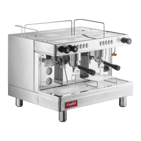
- Page 1 04/2022 USER MANUAL ESPRESSO MACHINES 236ECEM1 236ECEM2 236ECEM3 1 Group 2 Group 3 Group...
-
Page 2: Table Of Contents
Wiring Diagram (236ECEM1) . . . . . . . . . . . . . . . . . . . -
Page 3: General
GENERAL This is an electric machine user manual, in which operation, maintenance and safety information are specified . Please read and file it carefully . After unpacking, please check to ensure your machine has not been damaged during shipping . Please notify your service representative or qualified technician regarding all questions or concerns before installing . -
Page 4: Specifications
Every machine has an identification label placed on the front of the machine . The label includes information of model number, voltage, serial number, wattage, and its certificate . Please do not remove this label in order for technician to check electrical information in the future . 236ECEM1 236ECEM2 236ECEM3 Groups Boiler Capacity 6 Qt . -
Page 5: Setup
SETUP ( CONTINUED ) STARTING THE AUTOMATIC MACHINE 1 . Check and confirm that water source is in normal working order . 2 . Turn the power switch to On to initiate automatic system check . If boiler water level is not in the green zone, wait until the automatic water replenishment process is complete before proceeding to the next step . -
Page 6: Operation
OPERATION BREWING 1 . Fill the porta filter with coffee grounds and tamp . 2 . Secure the port filter to the espresso machine with a quarter turn . 3 . Use any of the presets to brew or use the continuous flow button . 4 . - Page 7 CLEANING & MAINTENANCE MACHINE BODY 1 . Wipe machine exterior with soft, slightly dampened cloth daily before starting operations . 2 . If necessary, a mild, non-corrosive cleaning agent may be applied to the cloth . DO NOT spray cleaning agents directly on the machine body to avoid corrosion and possible damage to circuits .
- Page 8 CLEANING & MAINTENANCE ( CONTINUED ) STEAM TUBE 1 . After making steamed milk, use a slightly moistened soft cloth to wipe steam tube . 2 . After wiping, release a steam burst through the tube to remove any residual milk remaining in the nozzle .
-
Page 9: Parts Diagram
PARTS DIAGRAM Description Description Hot Water Knob Foot Espresso Brewing Unit Control Panel Sight Glass (Boiler Water Level Check Window) Steam Knob 10 Espresso Filter Holder Brewing Group 11 Cup Rack 12 Water Pressure Gauge Steam Tube 13 Steam Pressure Gauge Main Power Switch 14 Hot Water Wand Drain Tray... -
Page 10: Wiring Diagram (236Ecem1)
WIRING DIAGRAM WIRING DIAGRAM 236ECEM1 236ECEM1 110±10% VAC 1Φ 50/60Hz pressure switch power switch heat element Motor connector & pump Operation panel Ground group1 connector Water inflow solenoid valve Water level probe To SSR Terminal 3 To SSR Terminal 4... -
Page 11: Wiring Diagram (236Ecem3)
WIRING DIAGRAM WIRING DIAGRAM 236ECEM2 236ECEM2 220±10% VAC 1Φ 50/60Hz pressure switch power switch heat element Motor connector & pump Operation panel Ground group2 group1 connector Water inflow solenoid valve Water level probe To SSR Terminal 3 To SSR Terminal 4 Temperature Flowmeter(group2) Protector... - Page 12 WIRING DIAGRAM WIRING DIAGRAM 236ECEM3 236ECEM3 220±10% VAC 1Φ 50/60Hz pressure switch power switch heat element Motor connector & pump Operation panel Ground group3 group2 group1 connector Water inflow solenoid valve Water level probe To SSR Terminal 3 To SSR Terminal 4 Flowmeter(group3) Temperature...
-
Page 13: Warranty
1 year from the date of delivery of the equipment. Only the equipment’s original purchaser may make a claim under this warranty. Estella reserves the right to approve or deny the repair or replacement of any part or repair request. The warranty is not transferable. - Page 14 1 Year Replacement Warranty Estella Caffe coffee brewers are backed by a 1-year replacement warranty. These select Estella products are warranted only to be free from defects in material and workmanship for a period of 1 year from the date of delivery. Proof of purchase is required to obtain warranty coverage.
Need help?
Do you have a question about the 236ECEM1 and is the answer not in the manual?
Questions and answers