
Subscribe to Our Youtube Channel
Related Manuals for Kobold NBK-01


Summary of Contents for Kobold NBK-01
- Page 1 Operating Instructions Bypass Level Indicator with Threaded Connection Model: NBK-01...
-
Page 2: Table Of Contents
Order codes ....................13 Dimensions ....................14 EC Declaration of Conformance ..............15 Manufactured and sold by: Kobold Messring GmbH Nordring 22-24 D-65719 Hofheim Tel.: +49(0)6192-2990 Fax: +49(0)6192-23398 E-Mail: info.de@kobold.com Internet: www.kobold.com page 2 NBK-01 K05/0322... -
Page 3: Note
Please read these operating instructions before unpacking and setting the unit into operation. Follow the instructions precisely as described herein. The instruction manuals on our website www.kobold.com are always for currently manufactured version of our products. Due to technical changes, the instruction manuals available online may not always correspond to the product version you have purchased. -
Page 4: Regulation Use
The optional electrical limit switches serve to signal a preset level. 4.3 Transmitter 00T A magnetostrictive transmitter can be mounted outside the bypass tube to teletransmit the level. A continuous standard signal of 4-20 mA is output by means of a fitted transmitter. page 4 NBK-01 K05/0322... -
Page 5: Operating Principle
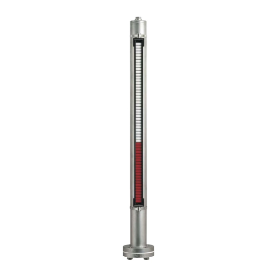
NBK-01 5. Operating Principle Kobold Bypass Level Indicators are used for continuous measurement, display and monitoring of liquid levels. The bypass tube is attached onto the side wall of the vessel. According to the law of communicating tubes the level in the bypass tube equals the level in the vessel. -
Page 6: Mechanical Connection
The height of the switch contacts may be selected at will. The cable connection must point downwards. The switch must be attached close to the bypass tube. The switching function of the switch is impaired by an enlarged air gap. page 6 NBK-01 K05/0322... - Page 7 Mount and tighten the remote sensor - if available and not already mounted - on the bypass tube with the ribbon clamps. The remote sensor must fully cover both process connections. The cable terminal box is situated at the top. NBK-01 K05/0322 page 7...
-
Page 8: Electrical Connection
When switching inductive loads, such as contactors, relays, etc., electrical limit values should not, also temporarily, be exceeded by e.g. voltage peaks. The use of a contact protection relay is recommended to avoid overloading the reed contacts. page 8 NBK-01 K05/0322... -
Page 9: Transducer: Magnetostrictive Transducer With 4-Wire Transmitter
To avoid faults caused by electrical fields from other circuits, the cables should not be installed adjacent to other high voltage power lines. Unscrew cover and run supply lines through cable gland. Connect the remote sensor to the electronics according to the following wiring diagram. NBK-01 K05/0322 page 9... -
Page 10: Commissioning
Hysteresis Hysteresis is the difference between contact closing and opening points. A hysteresis of approximately 15 mm float travel is achieved by factory tuning of the float magnet and contact strength. page 10 NBK-01 K05/0322... -
Page 11: Trouble Shooting
The bypass tube can now be mechanically cleaned. The inspection window for the roller indication is made of high-quality plexiglas (glass for high-temperature display). It should be cleaned with a suitable cleaning agent. The indicator requires no further maintenance. NBK-01 K05/0322 page 11... -
Page 12: Technical Information
4-20 mA Supply voltage: 24 V max. 150 mA Load: max. 500 Ω Max. length: 4000 mm Medium temperature: max. 120 °C Ambient temperature: -25 °C...+85 °C Accuracy: ±1 mm Housing: Aluminium pressure-cast Protection: IP 65 page 12 NBK-01 K05/0322... -
Page 13: Order Codes
NBK-01 Order codes Order details (Example: NBK-01 R15 RP0A) Desired Allowed medium density Design Order number* medium (Anzeigefehler ± 20 mm) density 1 kg/dm 0.9-1.18 kg/dm with roller indication NBK-01...RP0A 1 kg/dm 0.9-1.18 kg/dm with transmitter NBK-01...00TA 1 kg/dm 0.9-1.18 kg/dm with roller indication and transmitter NBK-01...RPTA... -
Page 14: Dimensions
NBK-01 Dimensions [in mm] page 14 NBK-01 K05/0322... -
Page 15: Ec Declaration Of Conformance
NBK-01 EC Declaration of Conformance We, KOBOLD Messring GmbH, Hofheim-Ts, Germany, declare that the bypass level indicators fulfil the following standards: Classification according to Pressure Equipment Directive 2014/68/EU NBK-01 Category assignment for dangerous media (from diagram 1) Density Category Category Category [kg/dm³]... - Page 16 Low Voltage Directive 2011/65/EU RoHS (category 9) 2015/863/EU Delegated Directive 2014/68/EU Module D, marking CE0575 Notified body: DNV GL Certificate No. PEDD000000R Hofheim, 15 Oct. 2021 H. Volz M. Wenzel General Manager Proxy Holder page 16 NBK-01 K05/0322...
Need help?
Do you have a question about the NBK-01 and is the answer not in the manual?
Questions and answers