Table of Contents
Advertisement
Quick Links
Advertisement
Table of Contents

Subscribe to Our Youtube Channel
Related Manuals for Kobold NUS-7 Series


Summary of Contents for Kobold NUS-7 Series
- Page 1 Instruction Manual Ultrasonic Level Meter Model: NUS-7...
-
Page 2: Table Of Contents
Dimensions [mm] ..................31 EU Declaration of Conformance ..............32 Manufactured and marketed by: Kobold Messring GmbH Nordring 22-24 D-65719 Hofheim Tel.: 06192-2990 Fax: 06192-23398 Internet: http: //www.kobold.com e-mail: info.de@kobold.com Seite 2 NUS-7 K03/0617... -
Page 3: Note
NUS-7 2. Note Please read these operating instructions before unpacking and putting the unit into operation. Follow the instructions precisely as described herein. The devices are only to be used, maintained and serviced by persons familiar with these operating instructions and in accordance with local regulations applying to Health &... -
Page 4: Operating Principle
NUS-7 5. Operating Principle The sensor emits an ultrasonic pulse train and receives the echoes reflected. The intelligent electronic device processes the received signal by selecting the echo reflected by the surface and calculates from the time of flight the distance between the sensor and the surface. -
Page 5: Installation (Liquid Level Measurement)
NUS-7 6.2 Installation (Liquid Level Measurement) Never mount two ultrasonic level-measuring devices in one container, because the two devices can interfere with each other's functioning. POSITION The optimal position of the NUS-4 is on the radius r = (0.3 … 0.5) R of the (cylindrical) tank / silo. -
Page 6: Installation (Open Channel Flow Measurement)
NUS-7 Ø 60 Ø 65 Ø 75 6.3 Installation (Open Channel Flow Measurement) For ultimate accuracy, install the sensor as close as possible above the expected maximum water level (see minimum measuring range). Install the device in a place defined by the characteristics of the metering channel along the longitudinal axis of the flume or weir. -
Page 7: Electrical Connection
NUS-7 7. Electrical Connection Make sure the terminals in the box are not under power (Use shielded cable 6 x 0.5 mm2 suggested in the technical data or stronger). After powering the necessary programming can be performed. Wire colours: Green – relay C1 output Yellow –... -
Page 8: Parameters - Description And Programming
NUS-7 8. Parameters – Description and Programming The HART interface of the NUS-7 provides for access to the whole parameter set and possibility of their programming. The parameter set can be reached by the use of the software run on the PC connected through HART modem to the loop. 8.1 Measurement configuration FACTORY DEFAULT: 000 P00: c b a Engineering Units... - Page 9 NUS-7 FACTORY DEFAULT: 11 P01: 1 a Measurement Mode Parameter value „a” will determine the basic measurement value that will be transmitted. Subsequently values for the relays are also relating to these quantities. Measure- Transmitted Display ment value symbol mode Distance Distance DIST...
- Page 10 NUS-7 VOL%= Transmitted value (H-DIST) P40…P45 Parameters to set P01(a) = P01(a) = P02(b) P04 = H P02(b) P05 ≥ X P04 = H P40…P45 P05 ≥ X P10 = X P11 = X 100% P40…P45 A: Shortest measurable distance B: Volume (content) pertaining to the greatest measurable level C: Whole value of the vessel D: diagram valid for the default value of P10 P11...
- Page 11 NUS-7 The maximum distance to be measured is the greatest distance between the surface transducer farthest level measured. The factory programmed, greatest distances (DEFAULT values) which can be measured by the units are listed in the table below. For the actual application the maximum distance to be measured i.e.
- Page 12 NUS-7 m/feet Minimum measuring distance X NUS-7 for liquids Sensor material PP / PVDF NUS-7 0.25/0.82 FACTORY DEFAULT: 0 P06: Far-end blocking Far-end blocking range below the level set in parameter P06. The far-end blocking can be used to avoid disturbing effect of stirrer or heaters at the bottom tanks.
-
Page 13: Current Output
NUS-7 8.2 Current Output FACTORY DEFAULT: 0 P08: Fixed current output By this step the output current can be set for a fix value selected from between 3.8 mA and 20.5 mA. This function is not operational as per the factory default: 0. Attention: fixing output current will make settings in P10, P11, P12 and P19 irrelevant. -
Page 14: Relay Output
NUS-7 FACTORY DEFAULT: 0 P12: a Error indication by the current output In case of error the NUS-7 will provide one of the current outputs below for the time the error prevails. (For errors see Chapter 10). Error indication by output current HOLD (hold last value) 3.8 mA... -
Page 15: Digital Communication
NUS-7 8.4 Digital communication FACTORY DEFAULT: 2 P19: Short (HART) address of the unit These addresses with 0 … 15 are, in accordance with the HART standard, for distinguishing units in the same loop. Address: 0 current output of 4 … 20 ma operational ... - Page 16 NUS-7 P25: a Selection of Echo within the measuring window FACTORY DEFAULT: 0 A so-called measuring window is formed around the echo signal. The position of this measuring window determines the flight time for calculation of the distance to the target. (the picture below can be seen on the test oscilloscope) Received Echo 2.
- Page 17 NUS-7 FACTORY DEFAULT: 0 P28: a Echo loss indication Echo loss Remark indication During short echo-loss (for the period of twice the time set in P20) analogue output will hold last value. After this period the current value according to the setting in P12 and via HART ERROR CODE 2 will be transmitted.
- Page 18 NUS-7 FACTORY DEFAULT: 0 P32: Specific gravity Entering a value (other than “0”) of specific gravity in this parameter, the weight will be displayed instead of VOL. Engineering unit should be [kg/dm ] or [lb/ft ] depending on P00 (c) Volume (content) measurement FACTORY DEFAULT: 00 P40: ba Tank shape...
- Page 19 NUS-7 Open channel flow measurement FACTORY DEFAULT: 00 P40: b a Devices, formula, data Devices, formula, data Also to be set Type Formula Qmin [l/s] Qmax “P” [cm] [l/s] 1.552 GPA- Q [l/s]= 60.87 * h 0.26 5.38 1.553 GPA- Q [l/s]= 119.7 * h 0.52 13.3...
- Page 20 NUS-7 FACTORY DEFAULT: 0 P41-45: Flume/weir dimensions P40=00 KOBOLD Parshall flumes P40=09 General Parshall flume 0.305 < P42(width) <2.44 P42 [m] 2.5 < P42 3.05 2.450 Q[l/s]= K * P42 * h 4.57...
- Page 21 NUS-7 P40= 10 Palmer-Bowlus (D/2) flume /s]= f(h1/P41) * P41 where h1[m]= h+(P41/10) P41 m D/10 P40= 11 Palmer-Bowlus (D/3) flume /s]= f(h1/P41) * P41 where h1[m]= h+(P41/10) P41 m D/10 P40= 12 Palmer-Bowlus (rectangular) flume /s]= C * P42 * h , where C= f(P41/P42) P41 m, P42 m...
- Page 22 NUS-7 P40= 13 Khafagi Venturi flume Q [m /s] = 1.744 P42 h 0.091 h P42 m h [m] P40= 14 P40=14 Bottom step weir 0.0005 < Q [m /s] < 1 0.3 < P42 [m] < 15 0.1 <...
- Page 23 NUS-7 P40= 16 Trapezoidal weir 0.0032 < Q [m /s] < 82 P40=16 20 < P41[°] < 100 0.5 < P42 [m] < 15 0.1 < h [m] < 2 Q [m /s] = 1.772 P42 h 2.47 1.320 tg(P41/2) ...
-
Page 24: 32-Point Linearisation
NUS-7 P40= 19 P40=19 THOMSON (90°-notch) weir 0.0002 < Q [m /s] < 1 0.05 < h [m] < 1 2.47 /s] = 1.320 h Accuracy: 3% P40= 20 P40=20 Circular weir 0.0003 < Q [m /s] < 25 0.02 <... -
Page 25: Informational Parameters (Read Out Parameters)
NUS-7 r (Right column) L (Left column) Level values Value assigned to measured transmit r(1) L(2) r(2) L(i) r(i) L(nn) r(nn) nn+1 P48: Number of linearisation data pairs Number of linearisation data pairs entered in the table. 8.6 Informational parameters (read out parameters) P60: Overall operating hours of the unit (h) P61: Time elapsed after last switch-on (h) P62: Operating hours of the relay (h) -
Page 26: Additional Parameters Of The Flow Metering
NUS-7 8.7 Additional parameters of the flow metering P76: Head of flow (LEV) (Read only parameter) The Headwater value can be checked here. This is the “h” value in the formula for flow calculation. P77: TOT1 volume flow totalised (resettable) P78: TOT2 volume flow totalised (non-resettable) Supplementary parameter of the logger P79: Free space of logger in percent... -
Page 27: Error Codes
NUS-7 9. Error Codes Error Error description Causes and solutions Code Memory error Contact local agent No Echo Echo loss See Action 5 and 6 Hardware error Contact local agent Display overflow Check settings Sensor error or improper Verify sensor for correct operation and check for correct installation/mounting, level in the dead band mounting according to the User’s Manual The measurement is at the reliability threshold Better location should be tried. -
Page 28: Parameter Table
NUS-7 10. Parameter Table Par. Page Description Value Par. Page Description Value d c b a d c b a Application/Engineering Units Echo loss indication Measurement Mode Blocking out a disturbing object Calculation units – Sound velocity values in different gases Maximum Measuring Distance Specific gravity Minimum Measuring Distance... -
Page 29: Sound Velocities In Different Gases
NUS-7 11. Sound Velocities in Different Gases The following table contains the sound velocity of various gases measured at. Gases Sound Gases Sound Velocity (m/s) Velocity (m/s) Acetaldehyde 252.8 Ethylene 329.4 Acetylene 340.8 Helium 994.5 Ammonia 429.9 Hydrogen 321.1 sulphide Argon 319.1 Methane... -
Page 30: Technical Data
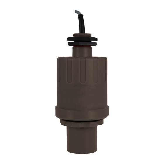
NUS-7 12. Technical Data Measuring range: 0.25...6 m / 0.8...20 feet Total beam angle: 5° Ambient temperature: -30..+80 °C (-22 °F...+176 °F) Process pressure abs.: 0.5...3 bar (7.5...43.5 psig) Process connection: G2, 2” NPT Materials: housing: PP or PVDF transducer: PP or PVDF cable sealing: EPDM,... -
Page 31: Order Codes
NUS-7 13. Order Codes Example: NUS-7 0 06 R9 3 4H 5 Model Sensor Range Connection Power supply Output Cable length material 4H = 4-20 mA 5 = standard 5 m ® 0 = PP + HART Y = accord. to R9 = G2 (standard) 06 = 0.25-6 m... -
Page 32: Eu Declaration Of Conformance
NUS-7 15. EU Declaration of Conformance We, KOBOLD Messring GmbH, Hofheim-Ts, Germany, declare under our sole responsibility that the product: Ultrasonic Level Meter Model: NUS to which this declaration relates is in conformity with the standards noted below: Safety requirements...
Need help?
Do you have a question about the NUS-7 Series and is the answer not in the manual?
Questions and answers