Kobold NBK Operating Instructions Manual
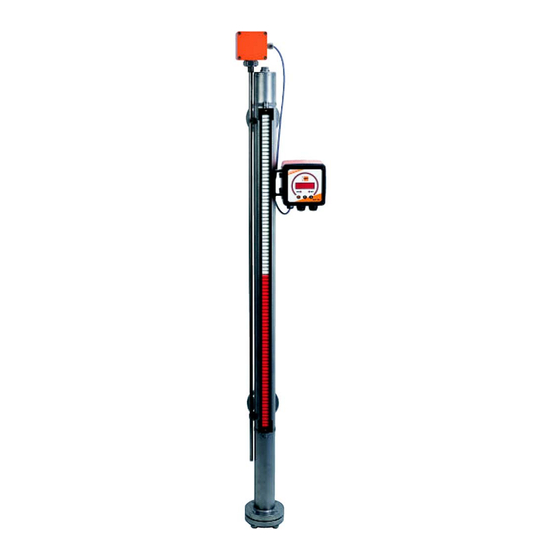
Bypass level indicator
Hide thumbs
Also See for NBK:
- Operating instructions manual (21 pages) ,
- Operating instructions manual (33 pages)
Table of Contents
Advertisement
Quick Links
Advertisement
Table of Contents

Subscribe to Our Youtube Channel
Related Manuals for Kobold NBK


Summary of Contents for Kobold NBK
- Page 1 Operating Instructions Bypass Level Indicator Model: NBK...
-
Page 2: Table Of Contents
Dimensions ....................17 EC Declaration of Conformance ..............28 Manufactured and sold by: KOBOLD Instruments Inc. 1801 Parkway View Drive Pittsburgh PA 15205-1422 Tel.: 412-788-2830 Fax: 412-788-4980 E-Mail: info@koboldusa.com Internet: www.koboldusa.com NBK 01/0322 page 2... -
Page 3: Note
Please read these operating instructions before unpacking and setting the unit into operation. Follow the instructions precisely as described herein. The instruction manuals on our website www.kobold.com are always for currently manufactured version of our products. Due to technical changes, the instruction manuals available online may not always correspond to the product version you have purchased. -
Page 4: Instrument Inspection
Bypass Level Indicator model: NBK 4. Regulation Use Any use of the Bypass level Indicator, model: NBK, which exceeds the manufacturer’s specification may invalidate its warranty. Therefore, any resulting damage is not the responsibility of the manufacturer. The user assumes all risk for such usage. -
Page 5: Bypass Measuring Tube System
The bypass tube is attached at the side of the vessel with a connecting flange or a threaded pipe. The installation position is always vertical. The NBK should only be used for liquids with the medium density specified on the nameplate. -
Page 6: Mechanical Connection
Normally it is sufficient to fix the complete NBK with both process connections. However, should the NBK be subjected to constant shock or strong vibrations it is recommended that the instrument is secured with rubber-damped tube clips. -
Page 7: Commissioning
Check that the density of the liquid is the same as the density given on the nameplate. Check that the float has been correctly installed with the marking "TOP" at the top. Check if dirt deposits in the bypass tube are blocking the float. NBK 01/0322 page 7... -
Page 8: Maintenance
The bypass tube can now be mechanically cleaned. The inspection window for the roller indication is made of high-quality plexiglass (glass for high-temperature display). It should be cleaned with a suitable cleaning agent. The indicator requires no further maintenance. NBK 01/0322 page 8... -
Page 9: Technical Information
½", ¾", 1", 1¼" NPT ANSI/ASME B1.20.1 ½", ¾", 1", 1¼" Bypass tube: Ø 60.3 mm, 1.4571 (NBK-03/ ... /10) Ø 71.0 mm, 1.4571 (NBK-31) Ø 76.1 mm, 1.4571 (NBK-32/33) NBK-03,-06,-07: flat gasket: <200 °C: PTFE; ≥200 °C: Klinger SIL ®... - Page 10 Aluminium, black anodised Carrier frame: Stainless steel 1.4301 Scale: stainless steel 1.4301 Medium temperature: -20...+200 °C Ambient temperature: -20...+200 °C Protection: IP66 * in case of multi-port design, a display length from 32 mm is not readable NBK 01/0322 page 10...
-
Page 11: Options
NBK-03/06 (pressure rating as process flange) Drain flange ¾” ASME, stainless steel 1.4571 (316 Ti) NBK-03/06 (pressure rating as process flange) Drain flange 1” ASME, stainless steel 1.4571 (316 Ti) NBK-03/06 (pressure rating as process flange) NBK 01/0322 page 11... - Page 12 Option M with connection box at 100 mm distance, max. medium temperature = +300 °C NBK- (Thermal screening option N mandatory with this option) 03/06/07/10/31/32/33 Option and connection box 5000 mm silicone cable, max. medium temperature = +400 °C NBK- (Thermal screening option N mandatory with this option) 03/06/07/10/31/32/33 NBK 01/0322 page 12...
- Page 13 Not possible with transmitter options H/F Only possible with option T (magnetostrictive sensor) or option M (reed chain with transmitter) Not possible with option T Note: Please pay attention to max. permissible temperature limits of individual components. Sketches of selected options NBK 01/0322 page 13...
- Page 14 405 Option ST Option TS Option A Model Dimension X NBK-03 NBK-06 NBK-07 NBK-10 Option HL Option HF (centred to dimension L) (centred to dimension L) Options process connection Option F/A Option R/N Option S NBK 01/0322 page 14...
- Page 15 CF340 Min. density difference Interface float = 150 kg/dm titanium (indicate both densities) *Option N not possible. Not for NBK-10, special float for special medium densities (taring) or reduced length A on request. NBK 01/0322 page 15...
-
Page 16: Order Codes
NAMUR, N/C, max. +200 °C (suitable for vessels with strong vibrations) RN200NC ³) Only possible with nominal diameter code 15/20/25/32 (female thread on request) Only possible with NBK-03/06 and nominal size code 15/20/25/32 Only possible with NBK-03 6) Not possible with NBK-10... -
Page 17: Dimensions
13. Dimensions NBK-03/06/07/10 with roller indicator/ball display NBK 01/0322 page 17... - Page 18 Dimension NBK Model Rated pressure ø x15 … x25 x32 F40 A40 F50 A50 PN 16 NBK-03 Class 150 PN 40 NBK-06 Class 300 60,3 130 PN 63 NBK-07 Class 400 PN 100 NBK-10 Class 600 PN160 NBK-31 Class900 150 245...
- Page 19 At intermediate temperatures e.g. 120 °C, a linear interpolation is to be carried out between 2 following creep resistance values, e.g. of 100 °C and 150 °C. The pressure/temperature assignment is valid for the following flange models with sizes up to DN 100 used by KOBOLD. Model No. and nomination: 05 Blind flange, 11 Welding neck flange...
- Page 20 NBK-… with reed chain model W NBK-… with transmitter model M NBK-… with transmitter model T NBK-… with transmitter options H/F (not possible with options VA/VF) NBK 01/0322 page 20...
- Page 21 NBK-… with thermal NBK-… with heating jacket option LX screen option N NBK 01/0322 page 21...
- Page 22 NBK-… with transmitter option MU NBK-… with transmitter option MS NBK-… with transmitter option MK NBK-… with transmitter and display option AE/HE or AC/HC NBK 01/0322 page 22...
- Page 23 Process connection NBK-… with transmitter NBK-… with transmitter option ST model M option ST model H/F option ST NBK-… with transmitter NBK-… with transmitter NBK-… with transmitter options MU and ST options MS and ST options MK and ST NBK 01/0322...
- Page 24 NBK-… with transmitter Process connection option TT display options AE/HE or AC/HC and option ST NBK-… with transmitter NBK-… with transmitter NBK-… with transmitter model M option TT model H/F option TT optiones MU and TT NBK 01/0322 page 24...
- Page 25 NBK-… with transmitter NBK-…with transmitter options MU and TT options MS and TT NBK-…with transmitter options MK and TT NBK 01/0322 page 25...
- Page 26 NBK-…with transmitter display options AE/HE or AC/HC and option TT NBK-…with indicating unit ADI-1, option C NBK 01/0322 page 26...
- Page 27 NBK-R NBK-RT200 NBK-RT400 NBK-RV/RN NBK 01/0322 page 27...
-
Page 28: Ec Declaration Of Conformance
PED-B-171 NBK-32 PN 250 PED-B-171 NBK-33 PN 320 PED-B-171 The limit contact for bypass level indicators NBK-R, NBK-RT are in conformity with the standards noted below: EN 61010-1:2020 Safety requirements electrical equipment measurement, control and laboratory use - Part 1: General requirements... - Page 29 Category III (IV) Diagram 1, vessel, group 1 dangerous fluids Module D, marking CE0575 Notified body: DNV GL Certificate No. PEDD000000R Hofheim, 18 March 2022 H. Volz M. Wenzel General Manager Proxy Holder NBK 01/0322 page 29...
Need help?
Do you have a question about the NBK and is the answer not in the manual?
Questions and answers