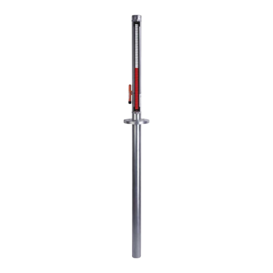
Kobold NBK-04 Operating Instructions Manual
Over-head level indicator
Hide thumbs
Also See for NBK-04:
- Operating instructions manual (21 pages) ,
- Operating instructions manual (26 pages)
Table of Contents
Advertisement
Quick Links
Advertisement
Table of Contents

Subscribe to Our Youtube Channel
Summary of Contents for Kobold NBK-04
- Page 1 Operating Instructions Over-Head Level Indicator Model: NBK-04...
-
Page 2: Table Of Contents
Technical Information .................. 10 Diagram Density / Length of Measuring Tube ..........11 11.1. NBK-04...8, diagram 8 ............... 11 11.2. NBK-04...6, diagram 6 ............... 12 11.3. NBK-04...4, diagram 4 ............... 13 ... -
Page 3: Note
Please read these operating instructions before unpacking and putting the unit into operation. Follow the instructions precisely as described herein. The instruction manuals on our website www.kobold.com are always for currently manufactured version of our products. Due to technical changes, the instruction manuals available online may not always correspond to the product version you have purchased. -
Page 4: Instrument Inspection
In case of damage, please inform your parcel service / forwarding agent immediately, since they are responsible for damages during transit. Scope of delivery: The standard delivery includes: Over-Head Level Indicator model: NBK-04 page 4 NBK-04 K01/0922... -
Page 5: Regulation Use
Therefore, any resulting damage is not the responsibility of the manufacturer. The user assumes all risk for such usage. Kobold over-head level indicators are used for continuous measurement, display and monitoring of liquid levels. The float inside the tank is attached by means of a connecting rod to the magnet carrier in the over-head tube. -
Page 6: Electrical Connection
The rollers change from white to red as the level rises and from red to white as the level falls. The level in a tank or a mixer is continuously displayed as a red column, even when the power fails. page 6 NBK-04 K01/0922... -
Page 7: Mechanical Connection
Initial strong vibrations, it is recommended that the Measurement instrument will be secured with damping-rubber tube clips. In any case, the over-head tube should Connection flange never be welded onto the tank. Final Measurement Initial Measurement NBK-04 K01/0922 page 7... - Page 8 Over-Head Level Indicator NBK-connection flange vessel connecting flange Min. vessel side Min. diameter of the Diameter NBK-04-tube Flange submerged tube on the vessel side 76.1mm 88.9 x 2 mm PN 16 DN 65/ 2 ½“ ANSI PN 16 DN 50/ 2“...
-
Page 9: Trouble Shooting
The viewing window of the roll display is made of high-quality Plexiglas and can be cleaned with a suitable cleaning agent if necessary. The indicator does not otherwise require any maintenance. NBK-04 K01/0922 page 9... -
Page 10: Technical Information
200 mm Measuring length: min. 600 mm max. 4000 mm Total length: see dimension drawing Min. density: 0.43 kg/dm ATEX approval: see separate description Housing: aluminium pressure-cast, terminal connection Cable entry: M16x1.5, brass nickel-platted Protection: IP 65 page 10 NBK-04 K01/0922... -
Page 11: Diagram Density / Length Of Measuring Tube
NBK-04 11. Diagram Density / Length of Measuring Tube 11.1. NBK-04...8, diagram 8 NBK-04 ...8: Float: titanium Connecting rod: stainless steel, 1.4571 Process connection: DIN EN 1092-1 flange, DN 50, 80, 100, ASME flange, 2“, 3”, 4” Overhead and tank tube: Ø 60.3 mm, continuous Min. -
Page 12: Nbk-04
NBK-04 11.2. NBK-04...6, diagram 6 NBK-04 ...6: Float: titanium Connecting rod: titanium Process connection: DIN EN 1092-1 flange, DN 50, 80, 100 ASME flange, 2“, 3”, 4” Overhead and tank tube: Ø 60.3 mm, continuous Min. medium density: 0.65 kg/dm... -
Page 13: Nbk-04
NBK-04 11.3. NBK-04...4, diagram 4 NBK-04 ...4: Float: titanium Connecting rod: stainless steel, 1.4571 Process connection: DIN EN 1092-1 flange, DN 65, 100 ASME flange, 2 ½“, 4” Bypass tube: Ø 60.3 mm Overhead and tank tube: Ø 76.1 mm Min. -
Page 14: Order Codes
NBK-04 12. Order Codes Order details: (Example: NBK-04 F50 00 0 8) Connection and Roller indication/ Medium density Model Material Transducers/Transmitters Options nominal size Ball display and meas. length F50 = DIN EN flange 00 = without DN 50 RP = PP-roller... -
Page 15: Dimensions
* in case of using a transmitter: dimension = 100/130/200 mm depending on transducer model dimension 130 mm in case of using a ball display Submersible length = measuring length + 320 mm Measuring length = submersible length -320 mm NBK-04 K01/0922 page 15... - Page 16 NBK-04 Required size of the mounting tube of the vessel side Ø NBK-04 Minimum-ø of the tube mounting tube of the vessel side Ø 76.1 mm Ø 88.9 mm x 2 Ø 60.3 mm Ø 76.1 mm x 2 page 16...
- Page 17 Measuring scale on stainless steel carrier Option M1 – engraved scale Scale from hard PVC or print on 1.4301 Option M2 – polyester foil (standard scale with ball display) NBK-… with indicating unit ADI-1V00W2F0, option C NBK-04 K01/0922 page 17...
-
Page 18: Disposal
(Cd, Hg, Li or Pb) of the heavy metal that is decisive for the classification as containing pollutants: 1. „Cd" stands for cadmium 2. „Hg" stands for mercury 3. „Pb" stands for lead 4. „Li" stands for lithium Electrical and electronic equipment page 18 NBK-04 K01/0922... -
Page 19: Eu Declaration Of Conformance
NBK-04 15. EU Declaration of Conformance We, KOBOLD-Messring GmbH, Hofheim-Ts, Germany, declare under our sole responsibility that the product: Over-Head level indicator model: NBK-04… to which this declaration relates is in conformity with the standards noted below: EN IEC 63000:2018 Technical documentation for the assessment of electrical...


Need help?
Do you have a question about the NBK-04 and is the answer not in the manual?
Questions and answers