
Related Manuals for Tense RGM-12S


Summary of Contents for Tense RGM-12S
- Page 1 ELEKTRİK - ELEKTRONİK SAN.TİC.A.Ş. RGM-12S USER MANUAL www.tense.com.tr www.tenseenerji.com...
-
Page 2: Table Of Contents
Index About RGM-12S Features Warnings Matters to be Considered in Power Factor Correction Considerations in Current Transformer Selection and Connection Device Maintenance Connection Diagram Screen Introduction Measurement Screens Setting Screens Settings Program (Intervention Logic) Change Determining the Step Count Current Transformer Test... -
Page 3: About Rgm-12S
About RGM-12S RGM-12S reactive power control relay is designed to reduce inductive powers not used by loads but drawn from the network. If inductive reactive power is drawn from the network, it intervenes by activating capacitors of appropriate value. In this way, it tries to bring the Cos fi value to the desired level. -
Page 4: Warnings
Warnings Use the device in accordance with the instructions set by us. After the device is mounted, leave a space of at least 10 cm. behind it. Fix the device to the front cover of the panel with the accompanying apparatus. Balance the inside and outside temperature in metal panels. -
Page 5: Considerations In Current Transformer Selection And Connection
It is recommended that the class of the current transformers to be used in compensation systems should be 0.5. Only X/5A current transformers can be connected to the RGM-12S. Make sure that there is no load before the current transformers. Otherwise, there will be differences in consumption and rates between the device and the electricity meter. -
Page 6: Connection Diagram
Single Phase Connection Diagram (L-N) -
Page 7: Screen Introduction
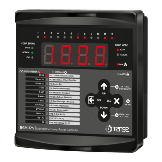
THD-I (%) Pr11: THD-I Set (%) Pr12: High Voltage Set (V) RGM-12S Monophase Power Factor Controller 1- Step LEDs: These are the LEDs that light up when the steps are active. 2- LED Display: It is the screen where all measurements, settings and notifications regarding the device are transferred to the user. -
Page 8: Measurement Screens
Measurement Screens ..8 8 8 8 - 9 8 5 8 8 8 8 3 5 0 8 8 8 8 2 3 0 DOWN DOWN Figure -1 (Cos Figure-2 (Current (A)) Figure-3 (Voltage (V)) φ) DOWN DOWN... -
Page 9: Setting Screens
Setting Screen The device shows the Cosine value on the measurements screen on the 8 8 8 8 - 9 8 5 left. While on any measurement screen, the SET button is pressed for 2 seconds in order to enter the menu. Figure-1 (2sec.) . -
Page 10: Settings
Settings Program (Intervention Logic) Change Changing the Program: The device has 7 different compensation programs. The first 6 of these modes operate automatically and when one of these modes is activated, the "AUTO" led on the device turns on. The 7th mode is manual program and works in manual mode. When this mode is active, the "MANUAL"... -
Page 11: Determining The Step Count
Settings Program (Intervention Logic) Change Start Over and Drop Mode: In this mode, steps should be at the lowest . . . 8 8 8 8 b A b b value in the first step and at the highest value in the last step. (From small to large value) Compensation is not made according to the step value, therefore there is no need for step measurement. -
Page 12: Current Transformer Test
Settings Current Transformer Test Performing Current Transformer Test: For the current transformer . . . 8 8 8 8 t E s t test, it is necessary to enter the Current Transformer Ratio first. Please examine the section "Current Transformer Ratio" in the manual to enter the current transformer ratio. -
Page 13: Current Transformer Ratio
Settings Current Transformer Ratio Entering Current Transformer Ratio: In order to change the 8 8 8 8 - 9 8 5 Current Transformer Ratio, press the “SET” button for 2 seconds while on the measurement screen (while MEASUREMENTS led is on). When you enter the setting menu, the MEASUREMENTS led will turn (2sec.) off and the SETTINGS led will light up. -
Page 14: Step Measurement
Settings Step Measurement Making Automatic Step Measurement: In order to make an 8 8 8 8 - 9 8 5 automaticly step measurement, press the “SET” button for 2 seconds while on the measurement screen (while MEASUREMENTS led is on). When you enter the setting menu, the MEASUREMENTS led will turn (2sec.) off and the SETTINGS led will light up. -
Page 15: Cosine Set Value
Settings Cosine Set Value Adjusting the Cosine Set Value: The target cosine set value for 8 8 8 8 - 9 8 5 compensation is set with this parameter. In order to change the cosine value, press the “SET” button for 2 seconds while on the measurement screen (while MEASUREMENTS led is on). -
Page 16: Step Drive Time
Settings Step Drive Time Adjusting the Step Drive Time: It determines the step drive 8 8 8 8 - 9 8 5 (activation) time to intervene in the power change in the system. In order to change this value, press the “SET” button for 2 seconds while on the measurement screen (while MEASUREMENTS led is on). -
Page 17: Step Discharge Time
Settings Step Discharge Time Adjusting the Step Discharge Time: It determines the capacitor 8 8 8 8 - 9 8 5 discharge (reactivate the same step) time. In order to change this value, press the “SET” button for 2 seconds while on the measurement screen (while MEASUREMENTS led is on). -
Page 18: Low Compensation
Settings Low Compensation Adjusting the Low Compensation Value: In case the Cosine value 8 8 8 8 - 9 8 5 stays under the Low Compensation Value for 3 minutes although the device activates all steps, it enters an undercompensation error, the alarm relay is energized, the LOW led flashes while the alarm and (2sec.) SETTINGS leds are constantly lit. -
Page 19: Harmonic Current
Settings Harmonic Current Adjusting the THD-I Value: If the Total Harmonic Distortion Current 8 8 8 8 - 9 8 5 (THD-I) value stays above the THD-I Set value for 120 seconds, the device enters a THD-I error, it stops compensation, the alarm relay isenergized (it deacitivates all steps), the alarm led turns on and the THDI led (Pr11: THD-I Set) flashes. -
Page 20: Blocking Access To Settings
Settings Blocking Access to Settings Blocking Access to Settings: You can use this feature to block the 8 8 8 8 - 9 8 5 device's settings from being changed by unauthorized personnel. To activate the feature: To activate this feature, press the “ESC” and “SET”... -
Page 21: Capacitor Calculation Table According To Connection Type
Capacitor Calculation Table According to Connection Type 3 Phase Phase-Netural Capacitor Connection Connection Powers (Q/3) (Q/6) 0,5 KVAR 0,16 KVAR 0,08 KVAR 0,33 KVAR 0,16 KVAR 1 KVAR 1,5 KVAR 0,5 KVAR 0,25 KVAR 2,5 KVAR 0,83 KVAR 0,41 KVAR 1,66 KVAR 0,83 KVAR 5 KVAR... -
Page 22: Factory Set Values
Factory Set Values Default Min. Max. Menu Parameter Unit Value value value C.T. Settings Current Transformer Ratio 2000 Cosine Set Value 1.000 0.800 1.000 Compensation Settings Cosine Tolerance Value Drive Time sec. Step Release Time sec. Time Discharge Time sec. Settings Settling Time Fixed... -
Page 23: Dimensions
Dimensions Left side view Front view 22mm 43mm 147mm Screwed side ear (apparatus) 45mm 34mm Rear view Side ear (apparatus) 114.5mm 138mm 147mm... -
Page 24: Technical Specifications
IP41 (Front Panel), IP20 (Body) Protection Class Panel Hole Sizes 140mm x 140mm Contact Information Web: www.tense.com.tr Muratpaşa Mh., Uluyol Cd., İşkent Sanayii Sitesi, E Blok, 1. Kat, Mail: info@tense.com.tr Bayrampaşa / İstanbul / TÜRKİYE Tel: 0212 578 04 38 - 48... - Page 25 User Notes...
- Page 26 QUALITY SOLUTIONS MADE IN TURKEY ELEKTRİK - ELEKTRONİK SAN.TİC.A.Ş. Energy and Compensation Tracking System Rev:1.00_210505 www.tenseenerji.com Document Number: DK-105-1...
Need help?
Do you have a question about the RGM-12S and is the answer not in the manual?
Questions and answers