Table of Contents
Advertisement
Quick Links
OPERATING AND MAINTENANCE
Made in
Italy for:
L-L 283.01-SW
ORIGINAL INSTRUCTIONS
MANUAL
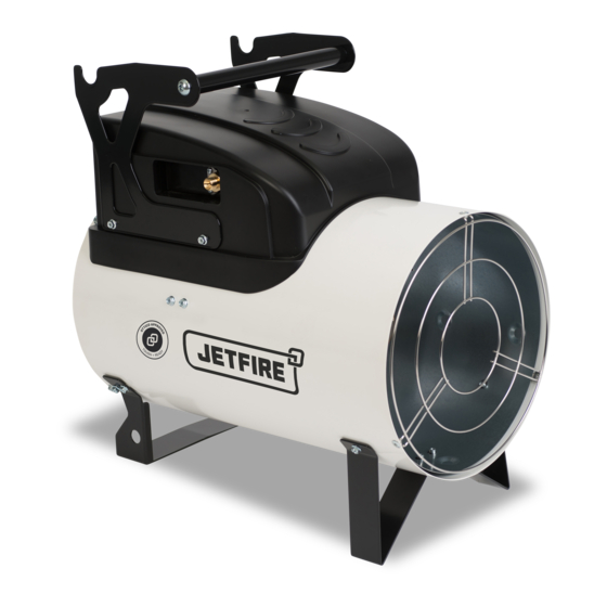
J20A & J45A
WARNING: THIS HEATER IS APPROVED FOR INDUSTRIAL USE ONLY.
Read and understand this instruction manual before operating this
unit and retain for future reference and pass on with the unit in the
event of a change of ownership.
Failure to follow operating, safety and maintenance instructions
outlined in this manual releases Spitwater Australia from any
responsibility for any accidents or damage incurred and may render
any warranty void.
Spitwater Australia Pty Ltd
953 Metry St
North Albury, NSW
Australia
1
Advertisement
Table of Contents

Related Manuals for Spitwater JETFIRE J20A


Summary of Contents for Spitwater JETFIRE J20A
- Page 1 Failure to follow operating, safety and maintenance instructions outlined in this manual releases Spitwater Australia from any responsibility for any accidents or damage incurred and may render any warranty void.
- Page 2 SPARE PARTS, ACCESSORIES & SERVICE Spitwater has an extensive range of spare parts and accessories to suit all your heating needs. For spare parts, accessories and service please refer to the contact section on www.spitwater.com.au or contact 1800 SPITWATER (1800 774 892).
-
Page 3: Technical Data
TECHNICAL DATA MODEL J20A J45A PRODUCT CODE JGDA020I JGDA045I UNIT PERFORMANCE HEAT OUTPUT 17.92 36.11 FUEL PRESSURE – REGULATOR 70max/30min 150max/40min FUEL PRESSURE – BURNER 70max/30min 150max/40min NOMINAL GAS CONSUMPTION MJ/h MINIMUM ROOM VOLUME FUEL Universal Universal FUEL TYPE GAS CYLINDER SIZE NOZZLE / INJECTOR SIZE ELECTRICAL ELECTRICAL SUPPLY... -
Page 4: Description Of Symbols
DESCRIPTION OF SYMBOLS The following symbols are used throughout this instruction booklet in order to mark important paragraphs or sections that are due particular attention. Their meaning is listed next to them for your attention. WARNING WARNING These are tips Failure to follow Failure to follow and instructions... -
Page 5: Important Safety Instructions And Precautions
UNIT COMPONENTS, FEATURES AND CONTROLS COMBUSTION CHAMBER IONISATION ELECTRODE (A model) 2 BURNER RESET BUTTON 3 COOLING FAN HEATING SWITCH 4 HANDLE 10 ROOM THERMOSTAT PLUG IGNITION ELECTRODE 11 POWER CORD THERMOCOUPLE (M model) IMPORTANT SAFETY INSTRUCTIONS AND PRECAUTIONS GENERAL •... -
Page 6: General Advice
• In addition to these operating and safety instructions, all accident prevention regulations as well as any standards relating to the installation and operation of heaters applicable in your country must be strictly followed. • This unit is not intended for use by children. Children must always be supervised when in the vicinity and ensure that they DO NOT play with the unit. -
Page 7: Extension Cord
have it replaced by an electrician or authorized service technician. (Type Y attachment) • DO NOT pull on the power cord in order to unplug the unit, remove the plug from the power outlet. 5. EXTENSION CORD • If using an extension cord, make sure it is a maximum length of 10 meters and sized according to cross section requirements as shown to the right. -
Page 8: Maintenance And Service
• Never tamper with any settings of the unit (sealed or unsealed) and make sure that a Spitwater authorized service agent carries out all servicing as required as this usually include checking the correct functioning and setting of all safety devices as well as the correct combustion of the unit. - Page 9 CONNECTION TO GAS CYLINDERS If the heater is run continuously on full output frost might form on the GAS cylinder indicating it is starting to “FREEZE”. This condition is caused by excessive vapour withdrawal and can be overcome by using various sizes of cylinders or multiple cylinder combinations. To minimise the “FREEZING”...
- Page 10 Warning Propane is heavier than air, therefore any gas leakage can cause gas stagnation on the floor or in any underlying room. A safety valve (b) may be ordered for protection in case of a damaged gas hose. Installation of this valve is mandatory if required by local installation laws and regulations.
-
Page 11: Transporting And Handling
Warning If the heater is not used continuously, stop it by first closing the gas supply stopcock and then switch it off or by turning down the thermostat this allows the gas in the gas tube to be fully used and avoids any future leak when removing the gas tube. -
Page 12: Maintenance
MAINTENANCE Warning The operations described in this section must only be performed by authorized personnel only. The following procedures must be carried out at regular intervals to ensure efficient operation of the heater. Ensure heater is disconnected from mains power before starting any work. The Usage v Maintenance Frequency table below shows the regular maintenance required for your heater, the maintenance interval and which maintenance can be done by the owner. -
Page 13: Checking The Electrical Connections
After detaching the power cable, check all electrical connections as follows: • Make sure that all connections are complete and tight. • If there are traces of dirt or corrosion, contact authorised Spitwater service agent to clean and/or replace the connections as necessary. - Page 14 For service please contact 1800 SPITWATER (1800 774 892) or refer to the contact section on www.spitwater.com.au Time interval for checks and replacement listed above are for units subjected to normal operating conditions.
- Page 15 OPERATOR INSPECTION AND MAINTENANCE CHECK LIST Symbols meaning: Unit is fit, Do it yourself Do not use the unit. Contact proceed refer to our Spitwater authorised service agent task service tips immediately CHECKED AND OK NEEDS ATTENTION DAILY PRIOR TO STARTING THE UNIT Ensure all guards, covers and shields are in place before operating the unit.
-
Page 16: Troubleshooting
• The heater fails to start and • No power supply • Check power specifications fan does not start • Check power connections • Contact Spitwater service agent • Mains switch in wrong • Select correct position position • Faulty operation of room •... -
Page 17: Safety Devices
The cause of the malfunction must always be investigated and eliminated before starting the heater again. Refer to ‘TROUBLESHOOTING guide contained within this manual for advice and if in any doubt, contact your authorized Spitwater service agent. Note the heater can restart only if reset button (8) is pressed (red lamp is off). - Page 18 Wiring Diagram AP Control box Capacitor MV Fan motor TA Room thermostat plug FUA Fuse EV Gas solenoid valve RV Switch RP Resistence PA Air pressure switch Reset switch EL Ionisation electode Overheat safety thermostat L-L 283.01-SW...
Need help?
Do you have a question about the JETFIRE J20A and is the answer not in the manual?
Questions and answers