
Related Manuals for FMS 64MM F-18 HORNET V2


Summary of Contents for FMS 64MM F-18 HORNET V2
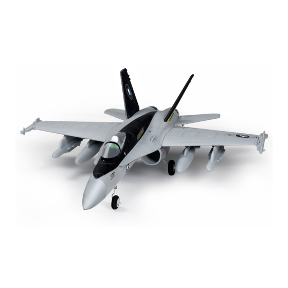
- Page 1 64MM F-18 HORNET V2 FMSMODEL.COM SIMPLE RIGID STABLE SIMPLE ASSEMBLY STRONG DURABLE EPO SMOOTH FLYING PERFORMANCE...
-
Page 4: Table Of Contents
·····················································································································18 Introductions FMS is pleased to announce that all 64mm ducted fan aircrafts are being upgraded. Inspired by the superior features of the original model, F-18 version two (V2) has improved mechanical and structural features that will enhance air performance and decrease assembly time. -
Page 5: Contents Of Kit
Wingspan: 675mm (26.6in) Overall Length: 934mm (36.8in) Flying Weight: Around 1000g (35.3 oz) Motor Size: Brushless 2840-KV3150 Wing Load: 81.3 g/dm² (0.19 oz/in²) Wing Area: 12.3 dm² (190.7 sq.in) ESC: 40A Servo: 9g Servo x 5 Contents of Kit Before assembly, please inspect the contents of the kit. The photo below details the contents of the kit and labels. -
Page 6: Model Assembly
Model Assembly Main Wing Installation 1.Slide the wing tube into the fuselage (fig1). 2.Install the left and right wing over the wing tube and into the wing slot of the fuselage (fig1). fig1 3.Secure the left and right wing to the fuselage using the 4 screws included (fig2) HKM3.0*10 fig2... - Page 7 Model Assembly Horizontal Stabilizer Installation: Carefully apply CA to the base and the side of the rear fuselage slot. Install the stabilizer into the place. Ensure the control horn faces down as shown (fig3) Note: Ensure the stabilizer horizontal axis is parallel to the wing. Adjust any misalignment before the glue dries thoroughly.
- Page 8 Model Assembly Clevis Installation: Install the clevis. (fig5) Refer to the Clevis Installation on page 12. fig5 Landing Gear Installation: Install landing gear with the included screws (fig6). KA2.0*8 fig6...
- Page 9 Model Assembly Missiles Installation: Correctly mount the wing missiles with CA. (fig7/fig8) fig7 fig8 Nose Cone Installation: Apply the nose cone to the front fuselage as diagram shows. Ensure the nose cone is on the correct side.(fig 9) Required Adhesives: fig9 Foam Safe Medium CA...
-
Page 10: Battery And Radio Installation
Battery and radio installation 1. Apply the hook tape to the cable end of the battery (fig 10). 2. Slide the battery into the battery compartment with the power supply cable toward the fore-end of the plane. Note: you may need to relocate the battery position to achieve the correct CG for your model. fig10 3. -
Page 11: Get Your Model Ready To Fly
Get your model ready to fly Important ESC and model information The ESC included with the model has a safe start. If the motor battery is connected to the ESC and the throttle stick is not in the low throttle or off position, the motor will not start until the throttle stick is moved to the low throttle or off position. -
Page 12: Check The Control Throws
Check the control throws The suggested control throw setting for FMS MODEL are as follows (dual rate setting): Tips: On first flight, fly the model in low rate. The first time you use high rates, be sure to fly at low to medium... -
Page 13: Clevis Installation
Clevis Installation a. Pull the tube from the clevis to the linkage. b. Carefully spread the clevis, then insert the clevis pin into the desired hole in the control horn. c. Move the tube to hold the clevis on the control horn. Control Horn and Servo Arm Settings The table shows the factory settings for the control horns and servo arms. -
Page 14: Center Of Gravity
Check the C.G. (Center of Gravity) When balancing your model, adjust the motor battery as necessary so the model is level or slightly nose down. This is the correct balance point for your model. After the first flights, the CG position can be adjusted for your personal preference. -
Page 15: Before Flying The Model
Before flying the model Find a suitable flying site Find a flying site clear of buildings, trees, power lines and other obstructions. Until you know how much area will be required and have mastered flying your plane in confined spaces, choose a site which is at least the size of two to three football fields - a flying field specifically for R/C planes is best. -
Page 16: Flying Course
Flying course Take off While applying power, slowly steer to keep the model straight. The model should accelerate quickly. As the model gains flight speed you will want to climb at a steady and even rate. It will climb out at a nice angle of attack (AOA). -
Page 17: Troubleshooting
Troubleshooting... -
Page 18: Spare Parts List Content
Spare parts list content Fuselage FMSPY101 FMSPY102 Main Wing Set FMSPY103 Rudder FMSPY104 Elevator FMSPY105 Missle-1 FMSPY106 Missle-2 FMSPY107 Oil Tank FMSPY108 Canopy FMSPY109 Cowl FMSPY110 Landing Gear Set FMSPY111 Linkage Rod FMSPY112 Pipe FMSPY113 Decal Sheet FMS64MM11B 64mm Ducted Fan FMSKV3150 2840-KV3150 Motor PRESC009... -
Page 19: Esc Instruction
ESC instruction...
Need help?
Do you have a question about the 64MM F-18 HORNET V2 and is the answer not in the manual?
Questions and answers