Table of Contents
Advertisement
Quick Links
SPECIAL NOTICE
This product is now licensed to Anodyne Electronics Manufacturing (AEM) from Northern
Airborne Technology (NAT)/Cobham Aerospace Communications (CAC). AEM is responsible
for all matters related to this product, including sales, support and repair services.
Please note the transition to convert product manuals and supporting documentation is an
ongoing process and is being addressed on an 'as needed' basis.
All references to NAT product part numbers (and associated images) are equivalent to AEM
product part numbers.
Contact info:
Anodyne Electronics Manufacturing Corp.
#15-1925 Kirschner Road
Kelowna B.C. Canada
V1Y 4N7
Email:
support@aem-corp.com
Toll Free: 1-888-763-1088
Phone: 1-250-763-1088
Fax: 1-250-763-1089
www.aem-corp.com
Advertisement
Table of Contents

Related Manuals for AEM AA21-400


Summary of Contents for AEM AA21-400
- Page 1 Please note the transition to convert product manuals and supporting documentation is an ongoing process and is being addressed on an ‘as needed’ basis. All references to NAT product part numbers (and associated images) are equivalent to AEM product part numbers.
- Page 2 REV 5.00 November 9, 2016 Anodyne Electronics Manufacturing Corp. 15-1925 Kirschner Road Kelowna, BC, Canada. V1Y 4N7 Telephone (250) 763-1088 Facsimile (250) 763-1089 Website: www.aem-corp.com © 2016 Anodyne Electronics Manufacturing Corp. (AEM), All Rights Reserved CONFIDENTIAL AND PROPRIETARY TO ANODYNE ELECTRONICS MANUFACTURING CORP.
- Page 3 © 2016 Anodyne Electronics Manufacturing Corp. (AEM), All Rights Reserved This publication is the property of AEM and is protected by Canadian copyright laws. No part of this document may be reproduced or transmitted in any form or by any means including electronic, mechanical, photocopying, recording, or otherwise, without the prior written permission of AEM.
- Page 4 AA21-400 Cabin PA System SM34 Installation and Operation Manual Prepared By: Checked By: Approved By: Tony Pearson Loen Clement Todd Blackstock Tom Betzelt Designer Designer R&D Manager Product Support Manager Dec 7, 2016 Dec 9/16 Dec 6, 2016 Dec 06, 2016 The status of this installation and operation manual is controlled by the revision shown on the title page.
-
Page 5: Table Of Contents
AA21-400 Cabin PA System SM34 Installation and Operation Manual Table of Contents Section Title Page Description Introduction Purpose of Equipment Features Specifications 1.4.1 Electrical Specifications 1.4.2 Physical Specifications 1.4.3 Environmental Specifications Accessories Required But Not Supplied Installation Introduction Unpacking and Inspection Installation Procedures 2.3.1... -
Page 6: Description
The AA21-400 also provides a low-level audio signal output that drives the input on a remote mounted power amplifier. The output is designed to drive the PA110/220 or PA250/700 series amplifiers. The AA21-400 provides generation of wail and yelp siren audio on the low level output when selected on the front panel. -
Page 7: Specifications
AA21-400 Cabin PA System SM34 Installation and Operation Manual Specifications 1.4.1 Electrical Specifications Power Supply Linear DC (with reverse & over voltage protection): Normal: +27.5 Vdc nominal. +22.0 Vdc minimum. +30.3 Vdc maximum. +18.0 Vdc emergency. Input Current: 2.3 A max. full speaker power (35 W) @ +27.5 Vdc. - Page 8 AA21-400 Cabin PA System SM34 Installation and Operation Manual Output Signals Speaker: Impedance and short circuit protected. 10% THD 20 W single tone into 8 @ 50% duty cycle. Continuous. 20 W voice/music into 8 @ 100% duty cycle. Continuous.
-
Page 9: Physical Specifications
AA21-400 Cabin PA System SM34 Installation and Operation Manual 1.4.2 Physical Specifications 1.11 0.03” (28.1 0.8 mm) Height 6.53 0.03” (165.9 0.8 mm) behind panel (including connector). Depth 4.96 0.03” (126.0 0.8 mm) behind panel. -
Page 10: Accessories Required But Not Supplied
AA21-400 Cabin PA System SM34 Installation and Operation Manual Accessories Required But Not Supplied Installation kit p/n AA21-400-IKC (crimp) or AA21-400-IKS (solder) is required to complete the installation. They consist of the following: AA21-400-IKC (crimp) Part #:D25SV-IKC Quantity Description Part #... -
Page 11: Installation
Verify that all items are present before proceeding and report any shortage immediately to your supplier. Complete the warranty card information and send it to AEM when the installation is complete. If you fail to complete the warranty card, the warranty will be activated on date of shipment from AEM. -
Page 12: Cautions
2.3.5.2 Power On checks WARNING The AA21-400 is a high power device, capable of producing tones at very high volume levels. Ensure that all personnel are well clear of the aircraft prior to keying the siren or PA. Failure to adhere to this warning could cause injury to personnel and/or damage to equipment. -
Page 13: Adjustments And Connections
Install the Cabin PA system and remote amplifier(s) and speaker(s) as applicable, and then power up the ship’s systems. Turn on all of the radios and other accessories required for this system. Check that the POWER ON LED on the AA21-400 illuminates when the power switch is selected to ON. -
Page 14: Continued Airworthiness
EXT SPKR LEVEL : Installed : 500 mVrms output level Not installed : 6.5 Vrms output level Continued Airworthiness Maintenance of the AA21-400 is ‘on condition’ only. Periodic maintenance of this product is not required. Build Standard: 5.00 Nov 09, 2016 Page 2-4 ENG-FORM: 805-0100.DOTX... -
Page 15: Installation Drawings
AA21-400 Cabin PA System SM34 Installation and Operation Manual Installation Drawings DRAWING REV. DESCRIPTION TYPE SERIAL # AA21-400-403-0 1.02 Cabin PA System Interconnect AA21-400-405-0 1.01 Cabin PA System Connector Map AA21-400-521-0 1.21 Cabin PA System Environmental Qual Form 1200 and up AA21-400-905-0 1.20... - Page 16 FEB 5/09 1.01 DOCCR02739 - ADDED NOTE B. OCT 14/16 1.02 ECO1054 - UPDATED TO AEM TITLEBLOCK. UNLESS OTHERWISE SPECIFIED: NAME DATE ANODYNE KELOWNA BC CANADA DIMENSIONS ARE IN INCHES [MM] ELECTRONICS (250)-763-1088 NOV 9/99 DRAWN TOLERANCES: MANUFACTURING CORP. WWW.AEM-CORP.COM FRACTIONAL_____________ ±0.0625"...
- Page 17 OCT 14/16 1.01 ECO1054 - UPDATED TO AEM TITLEBLOCK. UNLESS OTHERWISE SPECIFIED: NAME DATE ANODYNE KELOWNA BC CANADA DIMENSIONS ARE IN INCHES [MM] ELECTRONICS (250)-763-1088 SEP 10/99 DRAWN TOLERANCES: MANUFACTURING CORP. WWW.AEM-CORP.COM FRACTIONAL_____________ ±0.0625" CHECKED Oct 21, 2016 ANGULAR_______________ ±0.5°...
- Page 18 ENVIRONMENTAL QUALIFICATION FORM Description: Cabin PA System Document: AA21-400-521-0 Part #: AA21-4xx TSO #: C50c Manufacturer’s Specification and/or Other Applicable Specification: RTCA DO-160 Manufacturer: Anodyne Electronics Manufacturing Corp. Address: #15 - 1925 Kirschner Rd., Kelowna, BC, Canada. V1Y 4N7 DO-160 Rev:...
- Page 19 AA21-4xx Environmental Qualification Form Conditions Section Description of Conducted Tests Fluids Susceptibility 11.0 Equipment identified as Category X no test required Sand and Dust 12.0 Equipment identified as Category X no test required Fungus Resistance 13.0 Equipment identified as Category X no test required Salt Spray 14.0...
- Page 20 AA21-4xx Environmental Qualification Form REMARKS Tests were conducted at Northern Airborne Technology Ltd. AA21-401 was tested to 55,000 ft. End of Environmental Qualification Form Rev: 1.21 Oct 17, 2016 Page 3 of 3 ENG-FORM: 521-0100.DOTX CONFIDENTIAL AND PROPRIETARY TO ANODYNE ELECTRONICS MANUFACTURING CORP.
- Page 21 1.10 DOCCR01643 - "B" HOLE WAS "G"HOLE, MAY 26/06 "E" HOLES WERE "A" HOLES, FORMAT CHANGES. 1.20 ECO1054 - UPDATED TO AEM FORMAT AND REMOVED NAT LOGO. OCT 27/16 UNLESS OTHERWISE SPECIFIED: NAME DATE ANODYNE KELOWNA BC CANADA DIMENSIONS ARE IN INCHES [MM]...
- Page 23 DRAWING IS THE SOLE PROPERTY OF PAPER SIZE: CAGE CODE PART No.: REVISION ANODYNE ELECTRONICS MANUFACTURING. FINISH: L9015 AA21-400 1.30 ANY REPRODUCTION IN PART OR AS A WHOLE WITHOUT THE WRITTEN PERMISSION OF ANODYNE ELECTRONICS MANUFACTURING IS SCALE: DO NOT SCALE DRAWING DRAWING No.:...
-
Page 27: Operation
An internally generated siren is also available in WAIL or YELP modes. When the AA21-400 is turned on, a 28 Vdc switched signal is generated. This signal is used to turn on the PA amp relay (if connected in system). The high current DC power to operate the PA110/220 or PA250/700 is supplied by the aircraft. -
Page 28: Input Function Selection
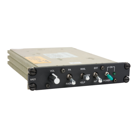
Volume Control Volume Control The volume control knob (VOL) on the front of the AA21-400 is used to adjust the level of the selected output. Rotating the knob clockwise will increase the volume, and counter-clockwise will decrease it. For external paging and rebroadcast operations, the volume should always be set between half and full level. -
Page 29: Mode Switches
Siren Mode The siren mode switch is a three position, centre-off locking switch on the front of the AA21-400. The siren is operated by selecting the mode (YELP or WAIL) and then activating a remote Siren key. The siren will sound only as long as the mode is selected to WAIL or YELP and the Siren key is activated.
Need help?
Do you have a question about the AA21-400 and is the answer not in the manual?
Questions and answers