Table of Contents
Advertisement
Quick Links
SPECIAL NOTICE
This product is now licensed to Anodyne Electronics Manufacturing (AEM) from Northern
Airborne Technology (NAT)/Cobham Aerospace Communications (CAC). AEM is responsible
for all matters related to this product, including sales, support and repair services.
Please note the transition to convert product manuals and supporting documentation is an
ongoing process and is being addressed on an 'as needed' basis.
All references to NAT product part numbers (and associated images) are equivalent to AEM
product part numbers.
Contact info:
Anodyne Electronics Manufacturing Corp.
#15-1925 Kirschner Road
Kelowna B.C. Canada
V1Y 4N7
Email:
support@aem-corp.com
Toll Free: 1-888-763-1088
Phone: 1-250-763-1088
Fax: 1-250-763-1089
www.aem-corp.com
The document reference is online, please check the correspondence between the online documentation and the printed version.
Advertisement
Table of Contents

Related Manuals for AEM AA21-400

Summary of Contents for AEM AA21-400
- Page 1 Please note the transition to convert product manuals and supporting documentation is an ongoing process and is being addressed on an ‘as needed’ basis. All references to NAT product part numbers (and associated images) are equivalent to AEM product part numbers.
- Page 2 Telephone (250) 763-1088 Facsimile (250) 763-1089 Website: www.aem-corp.com © 2016 Anodyne Electronics Manufacturing Corp. (AEM), All Rights Reserved CONFIDENTIAL AND PROPRIETARY TO ANODYNE ELECTRONICS MANUFACTURING CORP. The document reference is online, please check the correspondence between the online documentation and the printed version.
- Page 3 © 2016 Anodyne Electronics Manufacturing Corp. (AEM), All Rights Reserved This publication is the property of AEM and is protected by Canadian copyright laws. No part of this document may be reproduced or transmitted in any form or by any means including electronic, mechanical, photocopying, recording, or otherwise, without the prior written permission of AEM.
- Page 4 AA21-400 Cabin PA System SM34 Maintenance Manual Prepared By: Checked By: Approved By: Tony Pearson Loen Clement Todd Blackstock Tom Betzelt Designer Designer R&D Manager Product Support Manager Dec 7, 2016 Dec 9/16 Dec 7, 2016 Dec 07, 2016 The status of this Maintenance Manual is controlled by the revision shown on the title page. The status of each section is controlled by revision shown in the footer of each page.
-
Page 5: Table Of Contents
AA21-400 Cabin PA System SM34 Maintenance Manual Table of Contents Section Title Page Theory Introduction Overview 4.2.1 Main Subassembly 4.2.2 Control Interface Subassembly 4.2.3 Backlighting Subassembly Theory of Operation 4.3.1 Power Supply 4.3.2 Mic Input 4.3.3 Receive/CD Inputs 4.3.4 Sirens 4.3.5... - Page 6 AA21-400 Cabin PA System SM34 Maintenance Manual Supplements Introduction Supplement Listing Maintenance Manual Page v ENG-FORM: 823-0101.DOTX CONFIDENTIAL AND PROPRIETARY TO ANODYNE ELECTRONICS MANUFACTURING CORP. The document reference is online, please check the correspondence between the online documentation and the printed version.
-
Page 7: Theory
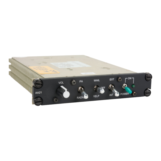
Overview The AA21-400 Cabin PA control unit is designed to provide centralized control for an aircraft’s internal and external PA systems in one panel-mounted unit with an illuminated faceplate. All audio and keylines are interfaced to existing aircraft audio systems. Front panel switches provide selection of the various operational modes of the AA21 and a potentiometer provides output volume control. -
Page 8: Theory Of Operation
AA21-400 Cabin PA System SM34 Maintenance Manual Theory of Operation Refer to diagrams AA21-1A\401-0, AA21-4\401-0 and AA21-5\401-0 4.3.1 Power Supply Positive 28 Vdc power is supplied to the AA21 through connector J101 pins 1 and 2, and power ground is through connector J101 pins 14 and 15. -
Page 9: Receive/Cd Inputs
AA21-400 Cabin PA System SM34 Maintenance Manual After the mic gain amplifier, the mic signal is fed to solid state relay U103 where the signal may be selected or de-selected. Depending on selection mode, the mic signal is either fed to external speaker driver U109 or to speaker driver U110 and U113. -
Page 10: Sidetone Output
AA21-400 Cabin PA System SM34 Maintenance Manual rate adjustment through YELP potentiometer R222. The yelp siren also requires YELP/WAIL KEY to be active (grounded) in order for the siren to be heard. This will be described later in this section. -
Page 11: External Pa Output
AA21-400 Cabin PA System SM34 Maintenance Manual Selection of front panel switch S402 to EXT applies a ground on S402 pin 1 and J401 pin 8. The external speaker selection signal is routed to J102 pin 8 and the cathode of D105. Diode D105 acts as protection for U104 pin 4. -
Page 12: 3Db Input
AA21-400 Cabin PA System SM34 Maintenance Manual 4.3.10 +3dB Input The AA21 has an external active low input for affecting the gain of the mic amplifier U107, receive amplifier U114 and siren amplifier U115. Grounding the +3dB input energizes solid state relay U116 by allowing current to flow in diode D121 and resistor R164. -
Page 13: Maintenance
The Airworthiness Limitations section is FAA approved and specifies inspections and other maintenance required under 14 CFR §§ 43.16 and 91.403, unless an alternative program has been FAA approved. Maintenance of the AA21-400 is ‘on condition’ only. Periodic maintenance of this product is not required. Disassembly/Reassembly Refer to Exploded View drawings AA21\400\904-0, AA21-1A\904-0, AA21-4\904-0 and AA21-5\904-0. -
Page 14: Reassembly
AA21-400 Cabin PA System SM34 Maintenance Manual screws M8 and washers M11 (from the circuit board), and eight flathead screws M9 (six from the bottom of the unit, and two from the front). 5.3.1.8 Remove Main subassembly SA1 circuit board from chassis M1 by lifting the rear of the board first, and sliding it back until it clears Control Interface subassembly SA2. -
Page 15: Test Equipment
5.4.2.2 Subassembly Test Jigs The appropriate test jigs for use with the subassembly Alignment Procedures can be purchased from AEM. Test and Alignment Procedures For all maintenance procedures, refer to the following documents found at the end of this section. - Page 16 ACCEPTANCE TEST REPORT Part No.: AA21-400 Description: Cabin PA System Document #: AA21-400-518-0 Rev.: 1.32 Acceptance Test Procedure: AA21-400-614-0 ATP Rev.: See Build Standard Serial Number: __________ ATP Results Output Test Requirement Observation Pass 5. Performance Test 5.1 Switched Power 5.1.2...
- Page 17 Serial Number: __________ AA21-400 Acceptance Test Report ATP Results Output Test Requirement Observation Pass 5.5 Backlighting 5.5.1 Uniform backlighting 5.6 Power Off 5.6.1 AA21-400 ON extinguishes, TS-AAD ALRT extinguishes 5.7 J101 5.7.2 <1.7V 5.7.3 <1.7V 6. Visual Inspection No defects or omissions found...
- Page 18 SEALED 2014.01.28 11:48:04 ACCEPTANCE TEST PROCEDURE -08'00' Part No.: AA21-400 Description: Cabin PA System Document No.: AA21-400-614-0 Rev.: 1.31 Prepared By: Checked By: Approved By: Zack Pahlman Edward Uy Geoff Melton 2014.01. 2014.01.27 2014.01.27 12:16:16 13:08:49 18:05:43 -08'00' -08'00' -08'00' Revisions Rev.
- Page 19 ACCEPTANCE TEST PROCEDURE Part No.: AA21-400 Description: Cabin PA System Document No.: AA21-400-614-0 Rev.: 1.31 Product Description The AA21 provides control for an aircraft’s internal and external PA systems. Audio inputs include microphone, receive audio or CD input. Receive audio or PA mic input is selectable on the front panel.
- Page 20 AA21-400 Acceptance Test Procedure Test Setup Check test equipment for valid calibration labels. Figure 1: Test Setup WARNING Turning on the ALERT power switch S2 on TS-AAD will damage the unit under test. Set the TS-AAD switches as follows: a) DIR1 and DIR2 switches down.
- Page 21 AA21-400 Acceptance Test Procedure Connect AA21 connector J101 to TS-AAD connectors J101, J102 and to the TJ-252 using the TC21-400 test cable. Set the TJ-252 to 8 Ω. Connect the audio analyzer generator output to TS-AAD MIC INPUT. Connect the audio analyzer input to TS-AAD H/S OUT.
- Page 22 AA21-400 Acceptance Test Procedure External Speaker 5.3.1 PA Mic Input 5.3.1.1 Set the audio analyzer generator output to 1 kHz. Set the TS-AAD H/S OUT switch to the 3 position. 5.3.1.2 Depress and hold TS-AAD A1. The audio analyzer should read 500 ±50 mVrms with <1% THD.
- Page 23 AA21-400 Acceptance Test Procedure Set the AA21 output switch to INT. The audio analyzer should read 14.1 ±0.5 Vrms with 5.4.1.2 <10% THD. Set the TS-AAD RX1 switch to the down position. 5.4.1.3 Set the audio analyzer generator output to 350 Hz. Set the TS-AAD RX1 switch to the up position.
- Page 24 AA21-400 Acceptance Test Procedure Backlighting 5.5.1 Shield the AA21 faceplate from light as much as possible. Set TS-AAD LTS (+28) switch to the up position. The AA21 faceplate should illuminate with consistent (well distributed) backlighting. Set TS-AAD LTS (+28) to the down position.
- Page 25 ALIGNMENT PROCEDURE NAT Part No.: AA21-1A Description: Main Subassembly Document #: AA21-1A\628-0 Rev.: 1.20 Prepared By: Checked By: Approved By: Purpose of AA21-1A The AA21-1A, used in conjunction with an AA21-4, provides control for an aircraft’s internal and external PA systems. Audio inputs include microphone, receive or CD audio input. Receive audio is muted softly when the PA key is active.
- Page 26 AA21-1A Alignment Procedure Test Setup Check test equipment for valid calibration labels. Figure 1: Setup Set the TS-AAD switches as follows: a) DIR1 and DIR2 switches down. b) TX1 through TX5 switches down. c) RX1 through RX8 switches down. d) PILOT, COPILOT and PAX load switches to the 600 OHM position. e) ICS TIE LOAD switch to the OFF position.
- Page 27 AA21-1A Alignment Procedure Confirm there are shorting blocks on the following AA21-1A jumpers: a) JP104. b) JP105 pins 1 - 2. Set all AA21-1A trimpots to midway. Connect TJ-107 ribbon cable (part of TJ-107) to AA21-1A connector J102. Connect AA21-1A connector J101 to TS-AAD connectors J101, J102 and to the TJ-252 using the TC21-400 test cable.
- Page 28 AA21-1A Alignment Procedure 5.2.5 Disconnect the audio analyzer generator output from TS-AAD MIC INPUT connector J16. Set TS-AAD PAX3 LOAD switch S11 to the center position. Plug the headset into TS-AAD PAX3 connector (J4). Depress and hold TS-AAD A1 and speak into the headset microphone. Audio should be heard in the headset.
- Page 29 AA21-1A Alignment Procedure 5.3.2.7 Set TJ-107 siren mode switch to OFF. No siren audio should be present on the audio analyzer speaker. The audio analyzer should read <2 mVrms. Release TS-AAD A3. 5.3.3 Radio Input 5.3.3.1 Set TJ-107 input switch to RADIO. Depress and hold TS-AAD A1. The audio analyzer should read <2 mVrms.
- Page 30 AA21-1A Alignment Procedure 5.4.2 Short Circuit Protection Set the TJ-252 to 2.5 Ω. Connect an oscilloscope probe to the positive terminal of the TJ-252. 5.4.2.1 Connect the multimeter to the TJ-252. Set the multimeter to read AC Volts on the 60 V manual setting.
- Page 31 ALIGNMENT PROCEDURE NAT Part #: AA21-4 Description: Control Interface Subassembly Document #: AA21-4\628-0 Rev: 1.00 Prepared By: Checked By: Approved By: Purpose of AA21-4 The AA21-4 Control Interface subassembly provides front panel controls and annunciators for the AA21-4xx series Cabin PA System. Control switches include Power, EXT/INT, PA/RADIO, and WAIL/OFF/YELP.
- Page 32 AA21-4 Alignment Procedure Set up the AA21-4 as follows: a) R401 fully ccw b) S401-S403 to the down position c) S404 to the middle position Connect TJ-106 J101 to TS-AAD J101. Connect AA21-4 J401 to TJ-106 J102. Connect AA21-5 J501 to AA21-4 J402. Connect the multimeter to TS-AAD MIC INPUT.
- Page 33 AA21-4 Alignment Procedure Set AA21-4 S403 to the up position. TS-AAD DS8 and DS11 should illuminate red. TS-AAD DS9 and DS10 should go dark. 5.10 Set the multimeter to measure resistance. The multimeter should read < 2.5 Ω. 5.11 Adjust AA21-4 R401 fully cw. The multimeter should read between 9.0 and 11.0 kΩ.
- Page 34 P103 P102 25 PIN FEMALE DMIN 37 PIN MALE DMIN TO AA21 J101 TO TS-AAD J102 +28V LIGHTS +28V LTS RECEIVE HI RX1 HI RECEIVE LO RESERVED RX2 HI RESERVED P101 50 PIN MALE DMIN TO TS-AAD J101 LIGHTS GROUND +28V LTS GND 20 AWG +28VDC POWER...
- Page 35 PARTS LIST NAT Part #: Description: TC21-400 AA21 Test Cable Document#: Rev: TC21\400\701-0 1.00 Prepared By: Checked By: Approved By: MFR. P/N IDENT DESCRIPTION OR VALUE PACKAGE NAT P/N QTY. CONNECTORS P101 D-sub Plug, Solder Cup 50 Pin 20-10-050 P102 D-sub Plug, Solder Cup 37 Pin 20-10-037...
- Page 36 The document reference is online, please check the correspondence between the online documentation and the printed version.
- Page 37 The document reference is online, please check the correspondence between the online documentation and the printed version.
-
Page 38: Documentation And Drawings
Documentation and Drawings For Parts Lists in this manual and its related supplements, alternate manufacturers‘ part Note: numbers may be used. Consult AEM for approved alternate parts. 6.2.1 Product DRAWING REV. - Page 39 AA21-400 Cabin PA System SM34 Maintenance Manual AA21-1-924-0 1.10 Main Subassembly Component Locator 1015 to 1199 AA21-1-924-1 1.10 Main Subassembly Component Locator 1015 to 1199 AA21-1A-924-0 1.20 Main Subassembly Component Locator 041813 and up AA21-1A-924-0 1.10 Main Subassembly Component Locator...
- Page 40 Steve Kempf Tony Pearson Todd Blackstock Designer Designer R&D Manager Oct 26/16 Oct 17, 2016 Oct 21/16 Generated by Parts List Manager The document reference is online, please check the correspondence between the online documentation and the printed version.
- Page 41 The document reference is online, please check the correspondence between the online documentation and the printed version.
- Page 42 CABLE ASSEMBLIES IDC to IDC, Ribbon, 3" 26 Cond 08-60-2630 MECHANICAL PARTS Chassis, AA21 50-02-053 Cover, AA21-400 50-03-018 Faceplate, Blank, AA21-400 55-01-021 Label, Product, AA21 43-30-121 Fastener, Dzus, Black 25-25-008 Knob, Fluted, Rubber 40-18-002 Locking Hardware, D-sub, Pair 25 Pin...
- Page 43 CABLE ASSEMBLIES IDC to IDC, Ribbon, 3" 26 Cond 08-60-2630 MECHANICAL PARTS Chassis, AA21 50-02-053 Cover, AA21-400 50-03-018 Faceplate, Blank, AA21-400 55-01-021 Label, Photo Aluminum, Product 43-30-001 Fastener, Dzus, Black 25-25-008 Knob, Fluted, Rubber 40-18-002 Locking Hardware, D-sub, Pair 25 Pin...
- Page 44 The document reference is online, please check the correspondence between the online documentation and the printed version.
- Page 45 The document reference is online, please check the correspondence between the online documentation and the printed version.
- Page 46 The document reference is online, please check the correspondence between the online documentation and the printed version.
- Page 47 The document reference is online, please check the correspondence between the online documentation and the printed version.
- Page 48 The document reference is online, please check the correspondence between the online documentation and the printed version.
- Page 49 REVISIONS SWEEP GENERATOR DESCRIPTION DATE R212 U123 XR-2206 R220 1.10 ECR #1556 : F101 & F102 ADDED. U112, U120, U121 VAL CHANGE. JAN 3/00 C174 FSK IN 22 uF BYPASS 1.20 ECR #2051 : F101 WAS 2.5A FAST BLOW NAT PART# 23-10-025. APR 23/02 SYNC OUT R222...
- Page 50 REVISIONS SWEEP GENERATOR DESCRIPTION DATE R212 U123 XR-2206 R220 1.10 ECR #1556 : F101 & F102 ADDED. U112, U120, U121 VAL CHANGE. JAN 3/00 C174 FSK IN 22 uF BYPASS SYNC OUT R222 C173 WAV ADJ YELP SINUSOIDAL C175 WAV ADJ M OUT 1 uF 0.1 uF...
- Page 51 SWEEP GENERATOR R212 U123 XR-2206 R220 C174 FSK IN 22 uF BYPASS SYNC OUT R222 C173 WAV ADJ YELP SINUSOIDAL C175 WAV ADJ M OUT 1 uF 0.1 uF TONE GENERATOR SYM ADJ W OUT R206 SYM ADJ AM IN R219 U103 U122...
- Page 52 The document reference is online, please check the correspondence between the online documentation and the printed version.
- Page 53 The document reference is online, please check the correspondence between the online documentation and the printed version.
- Page 54 The document reference is online, please check the correspondence between the online documentation and the printed version.
- Page 55 The document reference is online, please check the correspondence between the online documentation and the printed version.
- Page 56 The document reference is online, please check the correspondence between the online documentation and the printed version.
- Page 57 The document reference is online, please check the correspondence between the online documentation and the printed version.
- Page 58 The document reference is online, please check the correspondence between the online documentation and the printed version.
- Page 59 The document reference is online, please check the correspondence between the online documentation and the printed version.
- Page 60 The document reference is online, please check the correspondence between the online documentation and the printed version.
- Page 61 The document reference is online, please check the correspondence between the online documentation and the printed version.
- Page 62 The document reference is online, please check the correspondence between the online documentation and the printed version.
- Page 63 The document reference is online, please check the correspondence between the online documentation and the printed version.
- Page 64 The document reference is online, please check the correspondence between the online documentation and the printed version.
- Page 65 PARTS LIST NAT Part #: Description: AA21-1A Main Subassembly Document#: Rev: AA21-1A\701-0 1.10 Prepared By: Checked By: Approved By: MFR. P/N IDENT DESCRIPTION OR VALUE PACKAGE NAT P/N QTY. CAPACITORS C101 SM, Ceramic, 50 V 1000 pF 1206 11-05-102 C102 Metalized Polycarbonate, 50 V 0.47 uF CK07...
- Page 66 AA21-1A Parts List MFR. P/N IDENT DESCRIPTION OR VALUE PACKAGE NAT P/N QTY. C142 Aluminum Electrolytic, 35 V 330 uF 10-34-337 C143 Aluminum Electrolytic, 35 V 330 uF 10-34-337 C144 SM, Ceramic, 100 V 0.01 uF 1206 11-06-103 C145 SM, Ceramic, 50 V 1000 pF 1206 11-05-102...
- Page 67 AA21-1A Parts List MFR. P/N IDENT DESCRIPTION OR VALUE PACKAGE NAT P/N QTY. D118 SM, Power Rectifier, 1A, 600 V MURS160T3 74-21-160 D119 SM, Power Rectifier, 1A, 600 V MURS160T3 74-21-160 D120 SM, Power Rectifier, 1A, 600 V MURS160T3 74-21-160 D121 SM, Power Rectifier, 1A, 600 V MURS160T3...
- Page 68 AA21-1A Parts List MFR. P/N IDENT DESCRIPTION OR VALUE PACKAGE NAT P/N QTY. RESISTORS R101 - R110 NOT INSTALLED R111 SM, Metal Film, 1/8 W, 1% 1.00 kOhm 1206 70-54-1003 R112 NOT INSTALLED R113 SM, Metal Film, 1/8 W, 1% 8.87 kOhm 1206 70-54-8873...
- Page 69 AA21-1A Parts List MFR. P/N IDENT DESCRIPTION OR VALUE PACKAGE NAT P/N QTY. R161 SM, Metal Film, 1/8 W, 1% 1.00 kOhm 1206 70-54-1003 R162 SM, Metal Film, 1/8 W, 1% 9.09 kOhm 1206 70-54-9093 R163 SM, Metal Film, 1/8 W, 1% 3.32 kOhm 1206 70-54-3323...
- Page 70 AA21-1A Parts List MFR. P/N IDENT DESCRIPTION OR VALUE PACKAGE NAT P/N QTY. R213 SM, Metal Film, 1/8 W, 1% 8.87 kOhm 1206 70-54-8873 R214 SM, Metal Film, 1/8 W, 1% 1.00 kOhm 1206 70-54-1003 R215 SM, Metal Film, 1/8 W, 1% 10.0 kOhm 1206 70-54-104...
- Page 71 AA21-1A Parts List MFR. P/N IDENT DESCRIPTION OR VALUE PACKAGE NAT P/N QTY. MECHANICAL PARTS M101 PCB, AA21 Main Rev 1.30 15-21-001 M102 Socket, Tin Crimp Lead DIP6 80-00-006 M103 Socket, Tin Crimp Lead DIP8 80-00-008 M104 Shield, uMetal 35-10-099 M105 Screw, Panhead, Phillips, Steel MS35206-214...
- Page 72 PARTS LIST NAT Part #: AA21-1A Description: Main Subassembly Document#: Rev: AA21-1A\701-0 1.00 Prepared By: Checked By: Approved By: MFR. P/N IDENT DESCRIPTION OR VALUE PACKAGE NAT P/N QTY. CAPACITORS C101 SM, Ceramic, 50 V 1000 pF 1206 11-05-102 C102 Metalized Polycarbonate, 50 V 0.47 uF CK07...
- Page 73 AA21-1A Parts List MFR. P/N IDENT DESCRIPTION OR VALUE PACKAGE NAT P/N QTY. C143 Aluminum Electrolytic, 35 V 330 uF 10-34-337 C144 SM, Ceramic, 100 V 0.01 uF 1206 11-06-103 C145 SM, Ceramic, 50 V 1000 pF 1206 11-05-102 C146 SM, Tantalum Molded, 20 V 2.2 uF 3528...
- Page 74 AA21-1A Parts List MFR. P/N IDENT DESCRIPTION OR VALUE PACKAGE NAT P/N QTY. D120 SM, Power Rectifier, 1A, 600 V MURS160T3 74-21-160 D121 SM, Power Rectifier, 1A, 600 V MURS160T3 74-21-160 D122 SM, Rectifier Schottky, 40 V, 1.0 A MBRS140T3 74-30-140 D123 SM, Power Rectifier, 1A, 600 V...
- Page 75 AA21-1A Parts List MFR. P/N IDENT DESCRIPTION OR VALUE PACKAGE NAT P/N QTY. R120 SM, Metal Film, 1/8 W, 1% 10.0 kOhm 1206 70-54-104 R121 SM, Metal Film, 1/8 W, 1% 1.00 kOhm 1206 70-54-1003 R122 NOT ISSUED R123 SM, Metal Film, 1/8 W, 1% 1.00 kOhm 1206 70-54-1003...
- Page 76 AA21-1A Parts List MFR. P/N IDENT DESCRIPTION OR VALUE PACKAGE NAT P/N QTY. R173 Trim Pot, Vert., Top Adj. 500 kOhm 3329H 60-49-505 R174 SM, Carbon Film, 1/8 W, 5% 47 kOhm 1206 70-50-474 R175 SM, Metal Film, 1/8 W, 1% 13.0 kOhm 1206 70-54-1304...
- Page 77 AA21-1A Parts List MFR. P/N IDENT DESCRIPTION OR VALUE PACKAGE NAT P/N QTY. TRANSFORMERS T101 Audio, PC Mount MET-31 35-10-031 T102 Audio, PC Mount 35-10-009 T103 Audio, PC Mount 35-10-050 T104 Audio, PC Mount 35-10-600 T105 Audio, PC Mount 35-10-600 INTEGRATED CIRCUITS U101 NOT INSTALLED...
- Page 78 The document reference is online, please check the correspondence between the online documentation and the printed version.
- Page 79 The document reference is online, please check the correspondence between the online documentation and the printed version.
- Page 80 The document reference is online, please check the correspondence between the online documentation and the printed version.
- Page 81 The document reference is online, please check the correspondence between the online documentation and the printed version.
- Page 82 The document reference is online, please check the correspondence between the online documentation and the printed version.
- Page 83 The document reference is online, please check the correspondence between the online documentation and the printed version.
- Page 84 The document reference is online, please check the correspondence between the online documentation and the printed version.
- Page 85 The document reference is online, please check the correspondence between the online documentation and the printed version.
- Page 86 The document reference is online, please check the correspondence between the online documentation and the printed version.
- Page 87 REVISIONS DATE DESCRIPTION 1.10 ECR #1556 : S401-S404 NAT PART # CHANGES (HIDDEN). FEB 11/00 J401 26 PIN STRIP PLUG S401 TO AA21-1x J102 POWER +28VDC POWER R402 +28VDC POWER DOWN 2.2k +28VDC POWER DS401 +28VDC SWITCHED GREEN +28VDC SWITCHED POWER +28VDC SWITCHED D401...
- Page 88 J401 26 PIN STRIP PLUG S401 TO AA21-1x J102 POWER +28VDC POWER R402 +28VDC POWER DOWN 2.2k +28VDC POWER DS401 +28VDC SWITCHED GREEN +28VDC SWITCHED POWER +28VDC SWITCHED D401 J402 1N4005 POWER GROUND 2 PIN STRIP SOCKET TO AA21-5x J501 28V LIGHTS LIGHTS HI LIGHTS GROUND...
- Page 89 PARTS LIST NAT Part #: Description: AA21-4 Control Interface Subassembly Document#: Rev: AA21-4\701-0 1.10 Prepared By: Checked By: Approved By: MFR. P/N IDENT DESCRIPTION OR VALUE PACKAGE NAT P/N QTY. DIODES D401 Rectifier, 1 A, 600 V 1N4005 DO-41 75-20-005 DISPLAYS DS401 LED, Green, Bi-pin 47-30-001...
- Page 90 PARTS LIST NAT Part #: Description: AA21-4 Control Interface Subassembly Document#: Rev: AA21-4\701-0 1.00 Prepared By: Checked By: Approved By: MFR. P/N IDENT DESCRIPTION OR VALUE PACKAGE NAT P/N QTY. DIODES D401 Rectifier, 1 A, 600 V 1N4005 DO-41 75-20-005 DISPLAYS DS401 LED, Green, Bi-pin 47-30-001...
- Page 91 The document reference is online, please check the correspondence between the online documentation and the printed version.
- Page 92 The document reference is online, please check the correspondence between the online documentation and the printed version.
- Page 93 J501 2 PIN STRIP PLUG TO AA21-4x J402 LIGHTS HI DS501 DS502 DS503 DS504 DS505 DS506 LIGHTS LO PROPRIETARY AND CONFIDENTIAL TO NAT LTD. DESIGNED NORTHERN AIRBORNE TECHNOLOGY LTD. DRAWN DATE OCT 7/99 TITLE BACKLIGHTING SUBASSEMBLY CHECKED SIZE CAGE CODE PART NO.
- Page 94 PARTS LIST NAT Part #: Description: AA21-5 Backlighting Subassembly Document#: Rev: AA21-5\701-0 1.00 Prepared By: Checked By: Approved By: MFR. P/N IDENT DESCRIPTION OR VALUE PACKAGE NAT P/N QTY. DISPLAYS DS501 Lamp, Wire Lead 28 VDC T 3/4 45-62-028 DS502 Lamp, Wire Lead 28 VDC T 3/4 45-62-028...
- Page 95 The document reference is online, please check the correspondence between the online documentation and the printed version.
-
Page 96: Bulletins
SM34 Maintenance Manual Section 7.0 Bulletins Introduction Service Bulletins released periodically by AEM are contained in this section. As new bulletins are issued, this section should be updated in chronological order with the earliest documents appearing first. Bulletin Listing Bulletin Number... - Page 97 The document reference is online, please check the correspondence between the online documentation and the printed version.
- Page 98 The document reference is online, please check the correspondence between the online documentation and the printed version.
- Page 99 Identification Procedure Stamp an "X" (blacken out # 3) on the mod status tag to indicate MOD 3 has been incorporated. Material Information The following parts are required to modify one AA21-400 to MOD 3 status. MFR. P/N IDENT DESCRIPTION...
- Page 100 The document reference is online, please check the correspondence between the online documentation and the printed version.
- Page 101 None. The next edition of the service manual will include the changes described in this bulletin. Procedure Instructions Modification Procedure 2.1.1 Refer to the AA21-400 Service Manual SM34, Section 5.3, for details regarding disassembly and reassembly. Page 2 of 3 Apr 11, 2007 ENG-FORM: 603-0130.DOT CONFIDENTIAL AND PROPRIETARY TO NORTHERN AIRBORNE TECHNOLOGY LTD.
- Page 102 Reassemble the remainder of unit in reverse order. Testing Procedure 2.2.1 Refer to the AA21-400 Service Manual SM34, Sections 5.4 and 5.5, for the test equipment listing and test procedures. Note: The AA21-407 has its own testing procedure. Refer to the manual supplement SM34\AA21-407\825-0 Section 5.1 for the appropriate test...
- Page 103 The document reference is online, please check the correspondence between the online documentation and the printed version.
- Page 104 Other Publications Affected None. Procedure Instructions Modification Procedure 2.1.1 Refer to the AA21-400 Service Manual, Section 5, for details regarding disassembly and assembly. 2.1.2 Remove faceplate M3. 2.1.3 Remove and retain the six screws from the back of the faceplate and remove the subassembly.
- Page 105 Service Bulletin # SM34\603-0003 Material Information The following parts are required to modify one AA21-403, AA21-407 or AA21-408. MFR. P/N IDENT DESCRIPTION OR VALUE PACKAGE NAT P/N Strip Plug, Single Row, PC Mnt 2 pin 20-00-002L Reference Documents All documents required to complete the modification can be found in the applicable service manual. End of Service Bulletin Apr 10, 2008 Page 3 of 3...
- Page 106 SM34 Maintenance Manual Section 8.0 Supplements Introduction AEM Service Manual Supplements, issued to provide information on derivative products, are contained in this section. As new supplements are received, this section should be updated in chronological order with the earliest documents appearing first.
Need help?
Do you have a question about the AA21-400 and is the answer not in the manual?
Questions and answers