Table of Contents
Advertisement
Quick Links
PROPRIETARY NOTICE
PROPRIETARY STATEMENT
This document contains confidential and proprietary information and is the property of Chelton Avionics, Inc., a subsidiary of
Cobham plc. It is to be provided in confidence on the condition that by receipt it is not reproduced or copied in whole or in part, or
used to furnish such information to others, or to make use of it for purposes other than specified by the Usage Statement. The
previous statement shall not apply to the extent that such statement violates any federal or state laws requiring such information to
be made available to the public. Non-current versions of this document must be returned to Chelton Avionics, Inc. or destroyed or
shredded in a manner that renders the document completely and totally unusable and illegible.
EXPORT CONTROLS STATEMENT
The technical data within this document is controlled for export under the export administration regulations (EAR), 15 CFR PARTS
730-774, violations of these laws may be subject to fines and penalties under the export administration act.
FCC STATEMENT
This device complies with part 15 of the FCC Rules. Operation is subject to the following two
conditions: (1) This device may not cause harmful interference, and (2) this device must accept any interference received, including
interference that may cause undesired operation. Before operating the products covered by this document, read the operating
instructions for safe usage. Regarding Part 15.21, changes or modifications not expressly approved by the party responsible for
compliance could void the user's authority to operate the equipment.
USAGE STATEMENT
The data in this document was developed only to maintain systems and/or parts manufactured by, manufactured for, or approved
by Cobham. The data may not be applicable to any other systems and/or parts, regardless of their apparent similarity to systems
and/or parts manufactured by, manufactured for, or approved by Cobham. Do not rely, in any way, on data in this document to
maintain or otherwise support systems and/or parts that were not manufactured by, manufactured for, or approved by Cobham,
without evidence that the Federal Aviation Administration or other regulatory agency has determined that the data in this document
is valid for such use. This document shall not be used for the development, manufacture, service, support, modify, overhaul or
obtain FAA or any other regulatory approval of any other products than are specified within.
Cobham assumes no liability whatsoever, whether contractual, warranty, tort or otherwise, for unauthorized work not performed in
accordance with Chelton Avionics, Inc. approved procedures.
DOCUMENT COPYRIGHTS
Recipients agree to hold the contents of this document in confidence and agree to use only for the recipients internal purposes to
maintain the referenced equipment. This document and its contents shall not be used, reproduced, transmitted, or distributed for
any other purpose. The recipient also agrees to not disclose, share, or copy for distribution any of the contents of this document to
any third party except as provided by written permission from Chelton Avionics, Inc. Copy or disclosure of the contents of this
document by anyone without the written approval of Chelton Avionics, Inc. may result in criminal or civil liability.
DISCLAIMER
The content of this document has been reviewed for accuracy and is believed to be reliable, however no responsibility is assumed
for typographical errors and inaccuracies. Chelton Avionics, Inc. reserves the rights to revise the contents within to improve
accuracy and apply updated information related to design and serviceability without prior notice to users. The latest published
revision is the only version authorized for use.
PROPERTY AND COPYRIGHT STATEMENT
The copyright and ownership of all manuals, drawings, specifications and data as may be provided by Chelton Avionics, Inc. within
this document shall remain the property of Chelton Avionics, Inc.
All other brand and product names are trademarks or registered trademarks of their respective holders.
Proprietary Information: Use or disclosure of this data is subject to the restrictions specified in the introductory
REVISION 1.00.150430
Copyright
©
Chelton Avionics, Inc.
All Rights Reserved
Cobham Aerospace
Communications
6400 Wilkinson Drive
Prescott, AZ USA 86301
T: (928) 708-1550
F: (928) 541-7627
section of this document
Published on
18 June 2015
These commodities, technology or
software are Controlled in
accordance with the United States
Export Administration Regulations.
United
When exported from the
States, diversion contrary to U.S.
Law is prohibited.
Page 1
Advertisement
Table of Contents

Subscribe to Our Youtube Channel
Related Manuals for AEM SM16


Summary of Contents for AEM SM16
- Page 1 PROPRIETARY NOTICE PROPRIETARY STATEMENT This document contains confidential and proprietary information and is the property of Chelton Avionics, Inc., a subsidiary of Cobham plc. It is to be provided in confidence on the condition that by receipt it is not reproduced or copied in whole or in part, or used to furnish such information to others, or to make use of it for purposes other than specified by the Usage Statement.
- Page 2 May 5, 2012 Anodyne Electronics Manufacturing Corp. 15-1925 Kirschner Road Kelowna, BC, Canada. V1Y 4N7 Telephone (250) 763-1088 Facsimile (250) 763-1089 Website: www.aem-corp.com © 2012 Anodyne Electronics Manufacturing Corp. (AEM), All Rights Reserved CONFIDENTIAL AND PROPRIETARY TO ANODYNE ELECTRONICS MANUFACTURING CORP.
- Page 3 © 2012 Anodyne Electronics Manufacturing Corp. (AEM), All Rights Reserved This publication is the property of AEM and is protected by Canadian copyright laws. No part of this document may be reproduced or transmitted in any form or by any means including electronic, mechanical, photocopying, recording, or otherwise, without the prior written permission of AEM.
- Page 4 CC450-0V2 Communications Controller SM16 Installation and Operation Manual Prepared By: Checked By: Approved By: Tom Betzelt Loen Clement Tony Pearson Product Support Designer Designer Manager May 5, 2012 Jun 11/12 June 11, 2012 The status of this installation and operation manual is controlled by the revision shown on the title page.
-
Page 5: Table Of Contents
CC450-0V2 Communications Controller SM16 Installation and Operation Manual Table of Contents Section Title Page Description Introduction Purpose of Equipment Design Features Specifications 1.4.1 Electrical Specifications 1.4.2 Mechanical Specifications 1.4.3 Environmental Specifications Unit Nomenclature Installation Introduction Unpacking and Inspection 2.2.1 Warranty... -
Page 6: Description
CC450-0V2 Communications Controller SM16 Installation and Operation Manual Section 1.0 Description Introduction The CC250/450 is a compact, easy to install communications controller. It is designed to provide Relay and/or Simulcast operation for up to 4 transceivers. With these functions, the aircraft can become an airborne repeater or a multi-frequency transmitting platform. -
Page 7: Specifications
CC450-0V2 Communications Controller SM16 Installation and Operation Manual Specifications 1.4.1 Electrical Specifications Input Power 28 Vdc Power Supply Current 600 mAdc (max) Lights Current 80 mAdc (max) @ +28 Vdc 400 mAdc (max) @ +5 Vdc Inputs (Each RT) MIC HI, MIC LO, PTT... -
Page 8: Environmental Specifications
Two transceiver model, Voice Storage, +5 VDC panel lighting. CC450-5V1 Four transceiver model, Voice Storage, +5 VDC panel lighting. NVG compatible lighting may be available. Contact AEM for more information and available models. End of Section 1.0 May 5, 2012 Rev: 2.00 Page 1-3 ENG-FORM: 800-0100.DOTX... -
Page 9: Installation
Verify that all items are present before proceeding and report any shortage immediately to your supplier. 2.2.1 Warranty All Anodyne Electronics Manufacturing Corp. (AEM) products are warranted for 2 years. See the website www.aem-corp.com/warranty for complete details. Continued Airworthiness Maintenance of the CC450-0V2 Communications Controller is ‘on condition’ only. Periodic maintenance of this product is not required. -
Page 10: Cautions
CC450-0V2 Communications Controller SM16 Installation and Operation Manual 2.4.2 Cautions CAUTION: Do not bundle any lines from this unit with transmitter coax lines. Do not bundle any logic, audio, or DC power lines from this unit with 400 Hz synchro wiring or AC power lines. -
Page 11: Post-Installation Checks
CC450-0V2 Communications Controller SM16 Installation and Operation Manual Unless otherwise noted, all wiring shall be a minimum of 22 AWG, except power and ground lines, which shall be a minimum of 20 AWG. Check that the ground connection is clean and well secured, and that it shares no path with any electrically noisy aircraft accessories such as blowers, turn and bank instruments or similar loads. -
Page 12: Mechanical Mounting
Ensure that proper mechanical support is provided under the chassis. Due to the shallow profile of the unit, the Dzus fasteners should not be relied upon for complete mechanical support. AEM recommends that it should be mounted above another unit, such as a control head, to provide better mechanical support. -
Page 13: Squelch Vox Level Adjustments
CC450-0V2 Communications Controller SM16 Installation and Operation Manual Ensure proper Squelch Disable operation by pushing the squelch test button for the transceiver. The RX/TX annunciator on the CC450-0V2 should light ORANGE. k) Repeat the above procedure for all active low disable transceivers connected to the CC450. -
Page 14: Squelch Vox Circuitry And Jumper Settings
CC450-0V2 Communications Controller SM16 Installation and Operation Manual Squelch VOX Circuitry and Jumper Settings CAUTION: The Squelch VOX circuitry adjustments are only accessible by removing the top cover of the unit. As this unit contains electrostatic discharge sensitive components, this should only be undertaken by a certified technician at a static protected workstation. -
Page 15: Receive Audio Vox Squelch Circuit Jumpers
CC450-0V2 Communications Controller SM16 Installation and Operation Manual 2.6.2.2 Auxiliary Board The diagram below shows the applicable section of the auxiliary board. CC450-xV2 Jumper JP201 (RT3) Position Squelch Disable Logic Polarity 1-3, 2-4 Active Low (Normal Position) 1-2, 3-4 Active High... -
Page 16: Jumper Jp101
CC450-0V2 Communications Controller SM16 Installation and Operation Manual 2.6.4 Jumper JP101 For correct operation, this jumper must be in the 1-2 position. This diagram is included to ensure that the installer can replace the jumper if it is accidentally dislodged. -
Page 17: Installation Drawings
CC450-0V2 Communications Controller SM16 Installation and Operation Manual AEM Part #: CC450-DMY is a fully assembled Dummy Load that allows operation to continue if the CC450-0V2 is removed for service. It consists of: Quantity Description AEM Part # D-sub plug, Solder cup... - Page 19 Confidential and Proprietary to NAT...
- Page 20 Confidential and Proprietary to NAT...
- Page 21 Confidential and Proprietary to NAT...
- Page 22 Confidential and Proprietary to NAT...
- Page 24 Confidential and Proprietary to NAT...
- Page 25 ACTIVE ACTIVE BOTH BOTH...
- Page 26 ACTIVE BOTH...
-
Page 27: Operation
CC450-0V2 Communications Controller SM16 Installation and Operation Manual Section 3.0 Operation Introduction Information in this section consists of the functional and operational procedures for the CC450-0V2 Communications Controller. All derivative units operate in a similar manner, but may have minor differences such as no transceiver annunciators. -
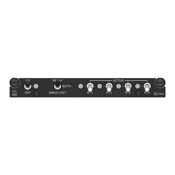
Page 28: Transceiver Controls
CC450-0V2 Communications Controller SM16 Installation and Operation Manual When the Power Switch is turned OFF, the CC450-0V2 will allow normal transmit and receive operation of all transceivers that are connected to the CC450-0V2. 3.3.2 Transceiver Controls 3.3.2.1 Transceiver Switches A transceiver is selected for control at the CC450-0V2 by putting the respective Transceiver Switch in the up (ACTIVE) position. -
Page 29: Alert Tones
CC450-0V2 Communications Controller SM16 Installation and Operation Manual In SIMULCAST mode, receive audio signals are not transmitted. Microphone audio is transmitted out on the transceiver as selected by the Audio Controller. If the switch on the CC450-0V2 is used to select that transceiver, then the microphone audio is transmitted on all transceivers selected at the CC450-0V2. -
Page 30: System Use
CC450-0V2 Communications Controller SM16 Installation and Operation Manual Up to 60 seconds of receive audio signal from the selected transceiver will be stored. If the receive audio signal is longer than 60 seconds, then only the first 60 seconds will be stored. When the receive activity is ended, the CC450-0V2 will transmit the stored signal out on the transceiver selected as active.
Need help?
Do you have a question about the SM16 and is the answer not in the manual?
Questions and answers