
Related Manuals for AVGear MHD44


Summary of Contents for AVGear MHD44
- Page 1 HDMI Matrix Switchers System User Manual Please read this manual carefully before using this product.
- Page 2 Notes: : : : This HDMI Matrix Switchers User Manual takes example of the Matrix model MHD44.
- Page 3 Safety Operation Guide In order to guarantee the reliable operation of the equipments and safety of the staff p lease , abide by the following proceeding in installation, using and maintenance: ⑴ ⑴ ⑴ ⑴ The system must be earthed properly. Please do not use two blades plugs and ensure the alternating power supply ranged from 100v to 240v and from 50Hz to 60Hz.
-
Page 4: Table Of Contents
2. MHD Packing of the Product ....................1 3. MHD Installation ........................2 4. Front View and Rear View of the Product ................ 2 Front view of MHD44 ........................2 Rear view of MHD44 ........................2 5. External Connection ......................2 Introduction of the Input and Output Connectors .............. -
Page 5: Introduction
With RS232 interface, it can be worked with PC, remote control system and any other far-end control system devices. The user manual takes MHD44 as the example, other models can take reference from it too. -
Page 6: Mhd Installation
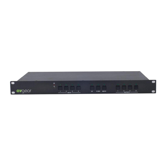
MHD Installation MHD matrix switchers adopt metal shell and can be stacked with other device. Moreover, they are rack-mountable enclosure and can be installed in the standard 19 inches case. Front View and Rear View of the Product Front view of HD44 Rear view of HD44 External Connection 5.1 Introduction of the Input and Output Connectors... -
Page 7: Connection With Computer
This RS-232 communication port is a female 9-pin D connector. The definition of its pins is as the table below. Function Unused Transmit Receive Unused Ground Unused Unused Unused Unused F 5-1 9HDF 5.2.2 Connection with Computer When the switcher connects to the COM1 or COM2 of the computer with control software, users can control it by that computer. - Page 8 HDMI pin function Signal Name Signal Name Number Number TMDS Data 2+ SHELL TMDS Data 2 Shield Hot Plug Detect TMDS Data 2- +5V Power TMDS Data 1+ Ground TMDS Data 1 Shield DDC Data TMDS Data 1- DDC Clock TMDS Data 0+ No Connect TMDS Data 0 Shield...
-
Page 9: Operation Of The Edid Management
Operation of the EDID management (For AVG HDMI/DVI matrix switcher, NOT including the 4x4 model) EDID communication introduction MHD/MDV matrix switcher are built in the EDID data inside, which can recognize most of the displays and video source. When the display or video source are connected, the EDID communication will start automatically. -
Page 10: Auto-Edid Management
Every time, you change the EDID data, all the displays will be blank for 3 seconds. The RS232 port will send out the feedback code. EDID management RS232 command The Operation of Front Panel Buttons Solution (ASCII, 9600bps. 8N1) Factory Default EDIDMInit. - Page 11 If there is a available display connected to output 1, the matrix switcher will copy the EDID data from this display. If the output 1 is not connected or display not available, the matrix switcher will go to the output2 automatically, to find the available data.
-
Page 12: Restore The Default Edid
[Y] is the input channel of matrix switcher Example If you send the “EDIDM2B1.” to the matrix switcher, you will copy the EDID data of output2 to the input1. If the second output is connected Sharp LCD, the input 1 is connected IBM PC. It means the Sharp LCD and IBM PC are directly EDID communication. -
Page 13: Operation Of The Control Panel
Operation of the Control Panel 7.1 Front Panel Description “AV” AV synchronal button: To transfer video and audio signal synchronously by the switcher Example: To transfer both the video and the audio signals from input channel No.3 to output channel No.4. Operation: Press buttons in this order “AV”,“3”,, “4””. -
Page 14: Usage Of The Remote Controller
4, Press the button for the second output channel number “4” Then, switching OK ! audio/video switching from “1” to “3” and “4” 8. Usage of the Remote Controller With the infrared remote controller, the matrix switcher could be control remotely. Because the function buttons on the remote controller are the same with the ones on the front control panel, the remote controller shares the same control operation and command format with the control panel. -
Page 15: Communication Protocol And Command Codes
9. Communication Protocol and Command Codes With this command system, the RS232 software is able to control and operate the MRG Matrix with remotely. Communication protocol: Baud rate: 9600 Data bit: 8 Stop bit: 1 Parity bit: none Command Command Functions Types Codes... - Page 16 [x1] B[x2]. Transfer both the video and the audio signals from the input channel [x1] to the output channel [x2]. [x1] Transfer both the video and the audio signals from the input channel B[x2],[x3],[x4]. [x1] to the output channels [x2], [x3] and [x4]. Status[x1].
- Page 17 S witch both video and audio signals synchronously: [x1] B[x2]. 、 、 、 、 Example: To transfer both the video and the audio signals from the input channel No.120 to the output channel No.12,13,15. Run Command: “120B12,13,15.” I nquire the input channel to the output channel [x]: Status[x]. 、...
-
Page 18: Troubleshooting & Maintenance
Compliant with High-bandwidth Digital Content Protection (HDCP) using DVI and HDMI 1.3 HDCP Management standards. The built-in HDCP management technology can analyze HDCP key, and realize the handshake internally. Audio General Digital Audio Supports HDMI audio transmitted through the RGB and Y, Cr, Cb lines, actively buffered Control Parts Serial Control Port RS-232, 9-pin female D connector... - Page 19 B. Check with oscilloscope or multimeter if there is any signal at the output end. If there is no signal output, it may be the output connection cord broken or the connectors loosen. C. Please make sure the destination device is exactly on the controlled output channel D.
Need help?
Do you have a question about the MHD44 and is the answer not in the manual?
Questions and answers