Advertisement
Scan for full manual
Step 1: Check what's in the box
VP-427X1 4K HDBT/HDMI Receiver/Scaler
1 Power adapter and cord
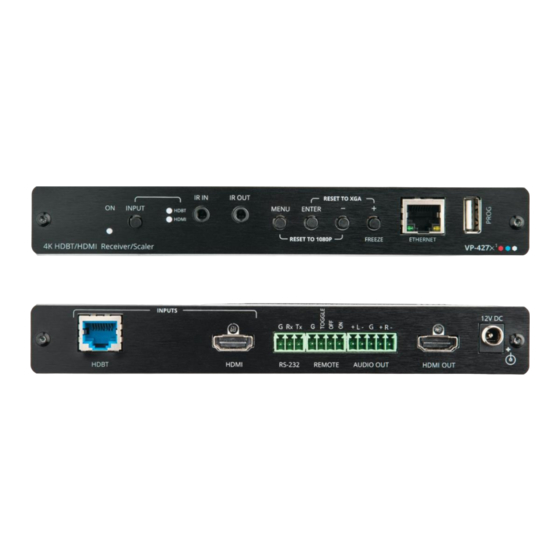
Step 2: Get to know your VP-427X1
#
Feature
1
ON LED
2
INPUT Select Button
3
INPUT
HDBT
LEDs
HDMI
4
IR IN 3.5mm Mini Jack
5
IR OUT 3.5mm Mini Jack
6
MENU Button
7
ENTER Button
– Button
8
9
FREEZE/+ Button
10
Ethernet RJ-45 Connector
11
PROG USB Connector
12
INPUT
HDBT RJ-45 with
Connectors
PoE (PD)
13
HDMI
14
RS-232 CONTROL 3-pin Terminal
Block Connector
15
REMOTE Contact-Closure 4-pin
Terminal Block Connector
AUDIO 5-pin Terminal Block
16
Connector
17
HDMI OUT Connector
18
12V DC Connector
The terms HDMI, HDMI High-Definition Multimedia Interface, and the HDMI Logo are trademarks or registered trademarks of HDMI Licensing Administrator, Inc.
Step 3: Mount VP-427X1
VP-427X1
Install
using one of the following methods:
•
Attach the rubber feet and place the unit on a flat surface.
•
Fasten a bracket (included) on each side of the unit and attach it to
a flat surface (see www.kramerav.com/downloads/VP-427X1).
•
Mount the unit in a rack using the recommended rack adapter
(see www.kramerav.com/product/VP-427X1).
VP-427X1 Quick Start
VP-427X1 Quick Start Guide
This guide helps you install and use your
Go to
www.kramerav.com/downloads/VP-427X1
upgrades are available.
Function
Lights green when device is powered.
Press to select the input (HDBT or HDMI).
Lights blue when the HDBT input is selected.
Lights blue when the HDMI input is selected.
Connect to an IR sensor to control a remote device connected to the transmitter side via HDBT
tunneling.
Connect to an external IR emitter to control a local device from the transmitter side.
Press to enter/exit the on-screen display (OSD) menu. Press together with the – button to reset the
output to 1080p resolution.
In OSD, press to choose the highlighted menu item. Press together with the FREEZE/+ button to
reset the output to XGA resolution (1024x768).
In OSD, press to move back through menus or decrement parameter values. Press together with
the MENU button to reset the output to 1080p resolution.
In OSD, press to move forward through menus or increment parameter values. When not in OSD,
press to freeze the display.
Connect to a PC via a LAN to setup and monitor the
as upgrade the firmware.
Connect to a USB stick to perform firmware upgrades.
Connect to a transmitter (for example, the Kramer TP-789Txr).
Connect to an HDMI source.
Connect to a serial controller or PC.
Connect to contact closure switches, an occupancy sensor and/or toggle switches (contact
between the desired pin and GND pin), to turn display on or off. See
Connect to a balanced stereo audio acceptor.
Connect to an HDMI acceptor.
Connect to the supplied power adapter.
VP-427X1
for the first time.
to download the latest user manual and check if firmware
1 Bracket set
4 Rubber feet
VP-427X1
• Ensure that the environment (e.g.,
maximum ambient temperature & air
flow) is compatible for the device.
• Avoid uneven mechanical loading.
• Appropriate consideration of equipment
nameplate ratings should be used for
avoiding overloading of the circuits.
• Reliable earthing of rack-mounted equipment should be maintained.
• Maximum mounting height for the device is 2 meters.
P/N: 2 9 0 0 - 3 0 1 4 2 7 QS
1 Quick start guide
via the Windows software, as well
Step 6: Operate
VP-427X1.
Rev: 3
Advertisement
Table of Contents

Related Manuals for Kramer VP-427X1


Summary of Contents for Kramer VP-427X1
- Page 1 PROG USB Connector Connect to a USB stick to perform firmware upgrades. INPUT HDBT RJ-45 with Connect to a transmitter (for example, the Kramer TP-789Txr). Connectors PoE (PD) HDMI Connect to an HDMI source. RS-232 CONTROL 3-pin Terminal Connect to a serial controller or PC.
- Page 2 Step 4: Connect inputs and outputs Always switch OFF the power on each device before connecting it to your VP-427X1. Connecting the audio output Wiring the RJ-45 Connectors To a balanced This section defines the TP pinout, using EIA /TIA 568B...
Need help?
Do you have a question about the VP-427X1 and is the answer not in the manual?
Questions and answers