Advertisement
Quick Links
V
ECTOR
Operating instructions for X2 devices with touch display
The X2 operating system was designed for universal controllers and sensors. Devices based on the X2 operating system
contain a multitude of standardized functions and application possibilities. From simple ventilation controllers for domestic
applications to HVAC system solutions for entire buildings. There is a suitable solution for almost every application. With the
EasySet program, the controllers can be conveniently read out, programmed and transferred to other controllers.
Content Overview
1
Overview ___________________________________________________________________________ 2
2
Display and Operation _________________________________________________________________ 2
3
General Operation ____________________________________________________________________ 6
4
Applicationspecific Operation ____________________________________________________________ 8
5
Extended Operating Level ______________________________________________________________ 9
Doc: 70-07-0951A, 20220504
Subjects to alteration
X2-O
PERATIONS
© Vector Controls LLC, USA
www.vectorcontrols.com
M
T
D
ANUAL
OUCH
ISPLAY
Page 1-18
Advertisement

Summary of Contents for VECTOR CONTROLS TRI2 Series
-
Page 1: Table Of Contents
EasySet program, the controllers can be conveniently read out, programmed and transferred to other controllers. Content Overview Overview ___________________________________________________________________________ 2 Display and Operation _________________________________________________________________ 2 General Operation ____________________________________________________________________ 6 Applicationspecific Operation ____________________________________________________________ 8 Extended Operating Level ______________________________________________________________ 9 Doc: 70-07-0951A, 20220504 © Vector Controls LLC, USA Page 1-18 Subjects to alteration www.vectorcontrols.com... -
Page 2: Overview
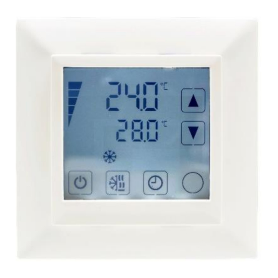
In addition, the various product descriptions and the programming instructions for technicians are contained in separate documents. This should facilitate the work with the different controllers and operating levels. Display and Operation 2.1 User Interface 2.1.1 OPT1 / TRI2 series X2 devices Figure 1: OPT1 / TRI2 Button Function... - Page 3 Overview This section explains the meaning of the symbols on the LCD Display of the different operation terminals. 2.2.1 OPT1 / TRI2 series Display Control loop indication When changing setpoints, the top bar indicates the control loop (1-4) that is being changed.
- Page 4 See separate alarm list for the meaning of the programmed alarms. The list is provided by the ALA7 configurator of the X2 device. ALA8 Sample display: Doc: 70-07-0951A, 20220504 © Vector Controls LLC, USA Page 4-18 Subjects to alteration www.vectorcontrols.com...
- Page 5 Most devices have a status LED. The position of the status LED is defined in the product data sheet. In normal operation, the LED flashes briefly once every 5 seconds. In an alarm or error condition, the LED flashes every second. Doc: 70-07-0951A, 20220504 © Vector Controls LLC, USA Page 5-18 Subjects to alteration www.vectorcontrols.com...
-
Page 6: General Operation
In case a start-up delay is active: - The controller remains switched off and displays the hand symbol until the delay has elapsed. Then the controller switches on and the hand symbol goes out. Doc: 70-07-0951A, 20220504 © Vector Controls LLC, USA Page 6-18 Subjects to alteration... - Page 7 If a real-time clock is present, the clock and time schedule settings are retained for 48 hours after the device has been powered for at least 10 hours. For additional information see chapter 5.1, page 9. Doc: 70-07-0951A, 20220504 © Vector Controls LLC, USA Page 7-18 Subjects to alteration www.vectorcontrols.com...
-
Page 8: Applicationspecific Operation
This is defined by the technician in the controller settings. If manual override for cascade controls is deactivated, the secondary control loop will not be shown on the display. Doc: 70-07-0951A, 20220504 © Vector Controls LLC, USA Page 8-18 Subjects to alteration... -
Page 9: Extended Operating Level
Year flashes: ( ) ( ) button for adjustment, ( ) button to save. Set Month Set Year Press the ( ) button (1x) to go back to the previous submenu. Doc: 70-07-0951A, 20220504 © Vector Controls LLC, USA Page 9-18 Subjects to alteration www.vectorcontrols.com... - Page 10 ) button to change the status. ➔ When schedule is ON, is displayed. Press the ( ) button (1x) to go back to the previous submenu. Doc: 70-07-0951A, 20220504 © Vector Controls LLC, USA Page 10-18 Subjects to alteration www.vectorcontrols.com...
- Page 11 ) button and adjust the time from 00:00…23:45 in 15 minutes steps with the ( ) ( ) button. ➔ 2 bars indicate setting step 2 is executed. Doc: 70-07-0951A, 20220504 © Vector Controls LLC, USA Page 11-18 Subjects to alteration www.vectorcontrols.com...
- Page 12 Start creating the next weekly schedules for program 2 to 12 as required. To go back to the previous submenu, press the ( ) button (1x). Doc: 70-07-0951A, 20220504 © Vector Controls LLC, USA Page 12-18 Subjects to alteration www.vectorcontrols.com...
- Page 13 = Positioning of the digital output (output must be in manual mode!) Hday = Annual time schedule (holiday) 1 bar indicates setting step 1 is executed. Doc: 70-07-0951A, 20220504 © Vector Controls LLC, USA Page 13-18 Subjects to alteration www.vectorcontrols.com...
- Page 14 Start creating the next holiday schedules for program 2 to 12 as required. To go back to the previous submenu, press the ( ) button (1x). Doc: 70-07-0951A, 20220504 © Vector Controls LLC, USA Page 14-18 Subjects to alteration www.vectorcontrols.com...
- Page 15 The heating output is deactivated. Auto operation: Auto = Heating and cooling changes automatically as required. Press the ( ) button to finish the setup. Doc: 70-07-0951A, 20220504 © Vector Controls LLC, USA Page 15-18 Subjects to alteration www.vectorcontrols.com...
- Page 16 ( ) button. ➔ FAN, the output number and the value are displayed. 10. To go back to the previous submenu, press the ( ) button (1x). Doc: 70-07-0951A, 20220504 © Vector Controls LLC, USA Page 16-18 Subjects to alteration www.vectorcontrols.com...
- Page 17 ➔ BASE and the software version of the X2 system and OP and the firmware version of the display / operation terminal are displayed alternatingly. Press the ( ) button to go back to the start. Doc: 70-07-0951A, 20220504 © Vector Controls LLC, USA Page 17-18 Subjects to alteration www.vectorcontrols.com...
- Page 18 ECTOR X2-O PERATIONS ANUAL OUCH ISPLAY Smart Sensors and Controls Made Easy! Quality - Innovation – Partnership Vector Controls LLC infous@vectorcontrols.com www.vectorcontrols.com Doc: 70-07-0951A, 20220504 © Vector Controls LLC, USA Page 18-18 Subjects to alteration www.vectorcontrols.com...
Need help?
Do you have a question about the TRI2 Series and is the answer not in the manual?
Questions and answers