
Related Manuals for Kyoritsu Electrical Instruments Works 5000


Summary of Contents for Kyoritsu Electrical Instruments Works 5000
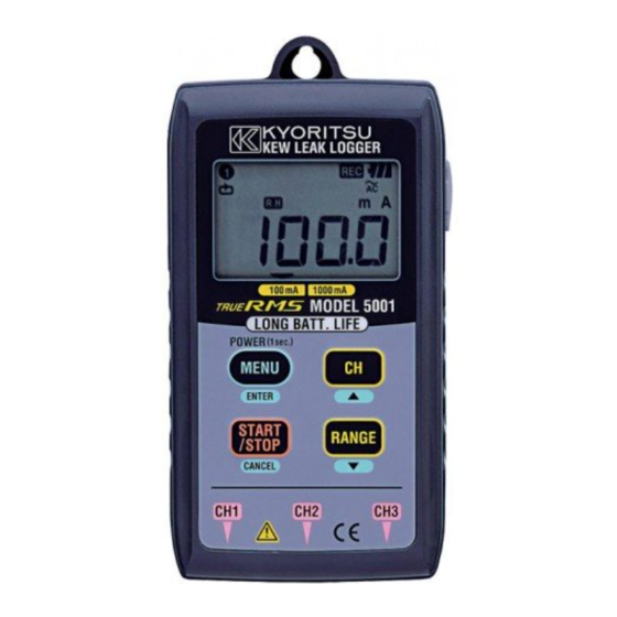
- Page 1 INSTRUCTION MANUAL Leak Logger for Measuring & Recording leakage current KEW LEAK LOGGER MODEL 5000/5001 KYORITSU ELECTRICAL INSTRUMENTS WORKS, LTD.
-
Page 2: Table Of Contents
Contents 1. Safety Warnings ................ 1 2. Features .................... 3 3. Specification .................. 4 4. Features .................... 6 4-1 Panel .................. 6 4-2 LCD display ................ 6 4-3 Message to be displayed on LCD .......... 7 5. Before starting measurement & record .......... 8 5-1 Power on/off the instrument ............ 8 5-2 Battery voltage check ..............8 5-3 Auto power off ................ 8 5-4 Sensor connection .............. 8 5-5 How to fix the instrument ............ 9 5-6 Max. recording time and Max. number of recording data ................10 6. How to use ..................11 6-1 Continuous recording mode ............12 6-2 Event recording mode ..............15 6-3 Max value recording mode ............18 6-4 Capture recording mode ............22 7. Measurement ...................26 7-1 Current measurement ..............26 7-2 Measuring and recording method ..........28... -
Page 3: Safety Warnings
1. Safety Warnings This instrument has been designed, manufactured and tested according to IEC 61010: Safety requirements for Electronic Measuring apparatus, and delivered in the best condition after passed the inspection. This instruction manual contains warnings and safety rules which must be observed by the user to ensure safe operation of the instrument and retain it in safe condition. Therefore, read through these operating instructions before using the instrument. - Page 4 DANGER ¡ Never make measurement on the circuit in which electrical potential to ground over AC300V exists. ¡ Do not attempt to make measurement in the presence of flammable gasses. Otherwise, the use of the instrument may cause sparking, which can lead to an explosion. ¡ Transformer jaw tips are designed not to short the circuit under test. If equipment under test has exposed conductive parts, however, ¡ extra precaution should be taken to minimize the possibility of shorting. ¡ Never attempt to use the instrument if its surface or your hand is wet.
-
Page 5: Features
2. Features ¡ This instrument is a leak logger for measuring and recording leakage current. ¡ Capable of recording leakage current from CH1 to 3 with leakage clamp sensor. ¡ Can measure and record max. AC1000mA(50/60Hz) with RMS. ¡ Recording modes are as follows: (1) Continuous recording mode Record the data continuously at set interval. (2) Event recording mode Can record total 8 data (for about 0.8sec.): prior to and subsequent ... -
Page 6: Specification
3. Specification ¡Continuous recording mode [RMS] (50/60Hz,Sine Wave) : Accuracy Measuring Accuracy when Range of the instrument range combining with sensor 0〜100.0mA ±2.0%rdg±10dgt 100mA ±1.0%rdg±5dgt 0〜1000mA ±2.0%rdg±6dgt 1000mA Crest Factor≦2.5 : Sine Wave accuracy +2%+5dgt ¡ Event/Max. value/ Capture recording mode [RMS] (50/60Hz,Sine Wave) : Measuring Accuracy Accuracy when Range range of the instrument combining with sensor 0〜100.0mA ±2.5%rdg±12dgt 100mA ±1.5%rdg±7dgt 0〜1000mA ±2.5%rdg±8dgt 1000mA ¡ Current detection (Event/Max. value/ Capture recording mode): ¡ Capture recording mode [instantaneous value] : Measuring Accuracy Accuracy when ... - Page 7 ¡ Display : Liquid crystal display ¡ Low battery warning : Battery mark display(in 4 levels) ¡ Overrange indication : "OL" mark appears when exceeding measuring range. (Max. indication 1049counts.) ¡ Auto power off : Power off function operates automatically after a switch remains for 3min. (when recording is stopped) ¡ Temperature & humidity range(guaranteed accuracy) : 23℃±5℃/Relative humidity 85% or less (no condensation) ¡ Operating temperature & humidity range : 0℃〜50℃/Relative humidity 85% or less (no condensation) ¡ Storage temperature & humidity range : -20℃〜+60℃/Relative humidity 85% or less (no condensation) ¡ Battery : DC6V: Alkaline battery(LR6) x 4pcs (M5000) DC9V: Alkaline battery(LR6) x 6pcs (M5001) ¡...
-
Page 8: Features
4. Features 4-1 Panel USB connecting # Power ON/OFF # MENU mode # Menu selection # Channel-switching # Setting change # Menu-switching # Setting entry # Set value change # Start recording # Stop recording # Range selction # Back to Menu # Menu-switching # Setting cancellation # Set value change Leak clamp sensor connecting part(3ch) 4-2 LCD display Auto power off Channel No. Clock/Timer is released Displayed while recording Recording mode Battery mark One-time system Scale in operation Unit Range hold Measuring range Guide for menu 100mA 1000mA operation ― 6 ―... -
Page 9: Message To Be Displayed On Lcd
4-3 Message to be displayed on LCD M e a n i n g M e s s a g e Sensor is not connected. Over-range Menu: Setting1 (SET.1) Menu: Setting2 (SET.2) Menu: Status1 (STS.1) Menu: Status2 (STS.2) Menu: End Continuous recording mode (LOGging) Event recording mode(detect) Max. value recording mode (Max) Capture recording mode (CAPture) PC data in transit Warning of memory clear ― 7 ―... -
Page 10: Before Starting Measurement & Record
5. Before starting measurement & record 5-1 Power on/off the instrument Instrument can be powered on by pressing "MENU/ENTER" button 1sec. or more when it is in OFF status. When all indications are displayed on the LCD, release the button. To power off the instrument, press "MENU/ENTER" button 1sec. or more while making normal measurement. (Instrument cannot be powered off while recording data. Stop the recording, and power off the instrument.) Then "OFF" will be displayed on the LCD and instrument is powered off when releasing then button. -
Page 11: How To Fix The Instrument
5-5 How to fix the instrument Instrument can be fixed as below. With either method, be sure to check the instrument is not easily dropped. If the instrument is not firmly fastened, it will drop and may be destroyed or damaged. 1) Hang the instrument on hook Capable of fixing the instrument with a hook or screw by using the hooking hole on the top. 2) Fix the instrument with magnet on its back. Can fix the instrument to metallic plate with the magnet on its backside. -
Page 12: Max. Recording Time And Max. Number Of Recording Data
5-6 Max. recording time and Max. number of recording data Max. recording time for Continuous measurement mode Recording When using 3CH When using 2CH When using 1CH interval 20,000data/1CH 30,000data/1CH 60,000data 1sec. 5:33:20 8:20:00 16:40:00 2sec. 11:06:40 16:40:00 1day/9:20:00 5sec. 1day/3:46:40 1day/17:40:00 3days/11:20:00 10sec. 2days/7:33:20 3days/11:20:00 6days/22:40:00 15sec. 3days/11:20:00 5days/5:00:00 10days/10:00:00 20sec. 4days/15:06:40 6days/22:40:00 13days/21:20:00 30sec. 6days/22:40:00 10days/10:00:00 20days/20:00:00 1min. 13days/21:20:00 20days/20:00:00 41days/16:00:00 2min. -
Page 13: How To Use
6. How to use Select one of the four recording modes, and start recording. (1) Record at regular interval in Continuous recording mode → P.12 Record the data at the selected intervals. (Interval: 1sec. 〜 60min) Best suited for checking Leakage varies with time as recording is performed at regular interval. (2) Detect leakage current in Event recording mode (LED blinks) → P.15 To check the cause of leakage: current value, time and frequency when exceeding the set current value can be checked. On each channel, LED blinks when exceeding set value, and can check time and current value of the last 10data with the instrument. It is helpful to check the cause of leakage on site. -
Page 14: Continuous Recording Mode
6-1 Continuous recording mode: Record at 1min. interval Step1 : Power on (1) Press "MENU/ENTER" button for 1sec. or more and power on the instrument. (2) Release the button when all indications are displayed on the LCD. (3) When instrument is powered on, it becomes measurement mode. Step2 : Check and change of set value (4) Press "MENU/ENTER" button and make the instrument to menu mode. (5) Check Setting1:"SEt.1" is displayed on the LCD, and press "MENU/ENTER" button. (6) Present recording mode is displayed on the LCD. Confirm "LOG" is displayed on the LCD, and press "RANGE/▼"button. (When "dtc", "̲ ̲̄" and "CAP" is displayed on the LCD, change the recording mode according to the procedure described in clause 9-2.Change of set value. - Page 15 (8) Then, present status of one-time system is displayed. In case of change, follow the procedure described in clause 9-2.Change of set value. One-time system can be selected either: On : Recording will stop when memory is full. Off : Overwrite the old data,and store the latest data (9) By pressing "RANGE/▼"button, setting 1 is complete and "End" message is displayed. Can back to "SEt.1" at first setting by pressing "MENU/ENTER" or "START/STOP, CANCEL" button. (10) Can back to initial measurement mode by pressing "START/STOP, CANCEL" button. Step3 : Clamp sensor connection, Preparation for measurement (11) Connect ...
- Page 16 (15) Following operations are available while recording. ¡ Display the measured value on each channel -> "CH/▲"button ¡ Recording condition : Display recorded max. value -> Menu "StS.1" ¡ Recording condition : RECALL -> Menu "StS.2" ¡ Check the set value at "SEt.1" and "SEt.2" Following things cannot be operated while recording, so check them carefully before starting to record. ¡ Power OFF ¡ Set value change at "SEt.1" and "SEt.2" ¡ Change of measurement range ¡ Data communication with PC When operation above things, recording shall be suspended. Step5 : Stop recording (16) Press "START/STOP" button 1sec or more to stop recording. (17) Recording will stop, and "REC" mark disappears. Step6 : Check the recorded data (18) Can check the recorded data while or after recording. ¡ Recorded qty. in percentage -> Menu "StS.1" ¡...
-
Page 17: Event Recording Mode
6-2 Event recording mode: Record with the set current of 15mA Step1 : Power on (1) Press "MENU/ENTER" button for 1sec. or more and power on the instrument. (2) Release the button when all indications are displayed on the LCD. (3) When instrument is powered on, it becomes measurement mode. Step2 : Check and change of set value (4) Press "MENU/ENTER" button and make the instrument to menu mode. (5) Check Setting1:"SEt.1" is displayed on the LCD, and press "MENU/ENTER" button. (6) Present recording mode is displayed on the LCD. Check "dtc" is displayed on the LCD, and press "RANGE/▼"button. ... - Page 18 (9) Then, present status of one-time system is displayed. In case of change, follow the procedure described in clause 9-2.Change of set value. One-time system can be selected either: On : Recording will stop when memory is full. Off : Overwrite the old data,and store the latest data (10)By pressing "RANGE/▼"button, setting 1 is complete and "End" message is displayed. Can back to "SEt.1" at first setting by pressing "MENU/ENTER" or "START/STOP, CANCEL" button. (11)Can back to initial measurement mode by pressing "START/STOP, CANCEL" button.
- Page 19 (16)Following operations are available while recording. ¡ Display the measured value on each channel -> "CH/▲"button ¡ Recording condition : Display recorded max. value -> Menu "StS.1" ¡ Recording condition : RECALL -> Menu "StS.2" ¡ Check the set value at "SEt.1" and "SEt.2" Following things cannot be operated while recording, so check them carefully before starting to record. ¡ Power OFF ¡ Set value change at "SEt.1" and "SEt.2" ¡ Change of measurement range ¡ Data communication with PC When operating above things, recording shall be suspended. Step5 : Stop recording (17)Press "START/STOP" button 1sec or more to stop the recording. (18)Recording will stop, and "REC" mark disappears. Step6 : Check the recorded data (19)Can check the recorded data while or after recording. ¡ Recorded qty. in percentage -> Menu "StS.1" ¡...
-
Page 20: Max Value Recording Mode
6-3 Max value recording mode: Record with the set current of 15mA Step1 : Power on (1) Press "MENU/ENTER" button for 1sec. or more and power on the instrument. (2) Release the button when all indications are displayed on the LCD. (3) When instrument is powered on, it becomes measurement mode. Step2 : Check and change of set value (4) Press "MENU/ENTER" button and make the instrument to menu mode. (5) Check Setting1:"SEt.1" is displayed on the LCD, and press "MENU/ENTER" button. (6) Present recording mode is displayed on the LCD. Check "̲ ̲̄" is displayed on the LCD, and press "RANGE/▼"button. (When "LOG", "dtc" and "CAP" is displayed on the LCD, change the recording mode according to the procedure described in clause 9-2.Change of set value. - Page 21 (8) Check/change the current set value on CH2 and CH3 as well. (9) Then, present status of one-time system is displayed. In case of change, follow the procedure described in clause 9-2.Change of set value. One-time system can be selected either: On : Recording will stop when memory is full. Off : Overwrite the old data,and store the latest data (10)By pressing "RANGE/▼"button, setting 1 is complete and "End" message is displayed. Can back to "SEt.1" at first setting by pressing "MENU/ENTER" or "START/STOP, CANCEL" button. (11)Can back to initial measurement mode by pressing "START/STOP, CANCEL" button.
- Page 22 Step4 : Start recording (15)Press "START/STOP" button for 3sec. or more and start to record. While the button is being pressed, "REC" mark blinks on the LCD. Keep the button pressed, then measured value and "REC" mark are displayed on the LCD and recording starts. When the button is released, recording will stop. (In this recording mode, recorded data will not be deleted when a record is performed ...
- Page 23 Step6 : Check the recorded data (19)Can check the recorded data while or after recording. ¡ Recorded qty. in percentage -> Menu "StS.1" ¡ Max, recorded value and when it is recorded (date and hour) on each channel -> Menu "StS.1" ¡ Number of detected current -> Menu "StS.2" ¡ RECALL(Display the latest 10data, date, hour and recorded data)-> Menu "StS.2" Step7 : Graphic display on PC (20)Can check the change of leakage current by transferring the data to PC and display it in graphic. Refer to the instruction manual for PC software of "KEW LOG Soft" which shows how to transfer the data to PC. ― 21 ―...
-
Page 24: Capture Recording Mode
6-4 Capture recording mode: Record with the set current of 15mA Step1 : Power on (1) Press "MENU/ENTER" button for 1sec. or more and power on the instrument. (2) Release the button when all indications are displayed on the LCD. (3) When instrument is powered on, it becomes measurement mode. Step2 : Check and change of set value (4) Press "MENU/ENTER" button and make the instrument to menu mode. (5) Check Setting1:"SEt.1" is displayed on the LCD, and press "MENU/ENTER" button. (6) Present recording mode is displayed on the LCD. Check "CAP" is displayed on the LCD, and press "RANGE/▼"button. (When "LOG", "dtc" and " " is displayed on the LCD, change ̲ ̲̄... - Page 25 (8) Then, present status of one-time system is displayed. In case of change, follow the procedure described in clause 9-2.Change of set value. One-time system can be selected either: On : Recording will stop when memory is full. Off : Overwrite the old data,and store the latest data (9) By pressing "RANGE/▼"button, setting 1 is complete and "End" message is displayed. Can back to "SEt.1" at first setting by pressing "MENU/ENTER" or "START/STOP, CANCEL" button. (10)Can back to initial measurement mode by pressing "START/STOP, CANCEL" button. Step3 : Clamp sensor connection, Preparation for measurement (11)Connect ...
- Page 26 Step4 : Start recording (14)Press "START/STOP" button for 3sec. or more and start to record. While the button is being pressed, "REC" mark blinks on the LCD. Keep the button pressed, then measured value and "REC" mark are displayed on the LCD and recording starts. When the button is released, recording will stop. (In this recording mode, recorded data will not be deleted when a record is performed continuously.The recorded data will be deleted when changing recording mode or sensor connecting channel. So transfer the important data to PC in advance.) (15)Following operations are available while recording.
- Page 27 Step6 : Check the recorded data (18)Can check the recorded data while or after recording. ¡ Recorded qty. in percentage -> Menu "StS.1" ¡ Max, recorded value and when it is recorded (date and hour) on each channel -> Menu "StS.1" Number of detected current -> Menu "StS.2" ¡ RECALL(Display the latest 10data, date, hour and recorded value)-> Menu "StS.2" Step7 : Graphic display on PC (19)Can check the waveform of leakage current by transferring the data to PC and display it in graphic. Refer to the instruction manual for PC software of "KEW LOG Soft" which shows how to transfer the data to PC.
-
Page 28: Measurement
7. Measurement 7-1 Current measurement DANGER ¡ Never make measurement on the circuit in which electrical potential to ground over AC300V exists. ¡ Transformer jaw tips are designed not to short the circuit under test. If equipment under test has exposed conductive parts, however, extra precaution should be taken to minimize the possibility of shorting. - Page 29 (1) By pressing " " button, the measured value at each channel to which the sensor connected will be displayed. → → When no clamp sensor is connected to the instrument, "nc" will be displayed on the LCD. (2) In continuous recording mode, by pressing " "button, range is changed in following sequence. Select any range from below ranges. Auto-range → 1000mA range → 100mA range → Auto-range In Event/Max. value/Capture recording mode, Auto-range is not available. Select the range before starting to record. ...
-
Page 30: Measuring And Recording Method
7-2 Measuring and recording method 1) Continuous recording mode Switch the channel to which the sensor is connected every at recording intervals. After recording, stand-by until next recording interval comes. Import 180data of input signal by sampling during 2cycles from the connected sensor, and calculate true RMS. Measurement result will be displayed at every 1sec. 2) Event recording mode Do sampling consistently at 1.6ms intervals, and compare and judge the peak value of sine wave that is converted into RMS and current set value. At the same time, calculate RMS every at ... - Page 31 3) Max. value recording mode Sampling continuously at 1.6ms intervals, and compare and judge the peak value of sine wave that is converted into RMS and current set value. At the same time, calculate RMS every at 100ms from the sampling value at every 3.3ms. When the event which exceeding detected current value happens, record will start and end when the value drops to 50% or less of set current value or for 10min with information of max value recorded at every 10sec and time. ...
-
Page 32: Recording
8. Recording (1) Recording starts by pressing "START/STOP" button 3sec or more, and mark is displayed on the LCD. Note: ¡ The channel on which the data is subject to record automatically recognize the clamp sensor, which is connected to a channel of the instrument, and record the data measured on the channel to which the sensor is connected. Do not connect a sensor to a channel on which no recording will perform. -
Page 33: Menu Operation
9. Menu operation 9-1 Menu operation Menu mode can be operated with following buttons to switch the indication, change or resister the set value. ENTER ▲ <Select item> <Switch item> <Change, resister> <Change the set value> CANCEL ▼ <Back to menu> <Switch item> <Cancellation of change> <Change the set value> Memo: When "▲" or "▼" mark is displayed at the left side on the LCD,the indicated direction of "CH/▲" and "RANGE/▼" button are available. 9-2. Change of set value (1) Press "MENU/ENTER" button while present setting is displayed on the LCD. (2) All indication on LCD will blink and be ready for changing the set value. (3) Set value can be changed with "CH/▲" or "RANGE/▼"button. (4) When the set value is being displayed, press "MENU/ENTER" button ... -
Page 34: Menu Flow Chart
9-3 Menu flow chart ― 32 ―... - Page 35 ― 33 ―...
- Page 36 <Menu setting 1: SEt.1 item> 1) "Recording mode Select one of the four recording mode. [LOG] : Continuous recording mode Make measurements and record the data at the selected intervals. [dtc] : Event recording mode Can record total 8data(approx. for 0.8sec.): prior to and subsequent to when exceeding the set current value. The LED for the CH on which the exceeding value is detected will blink. ] : Max. value recording mode ̲ ̲̄ When exceeding the set value, record the measured current value at every 10sec. The recording will be continued until the measured ...
- Page 37 <Menu setting 2: [SEt. 2] item> 1) Location information Set the location no. to identify the measuring and recording place. Location no. is linked to the location list in PC software and allows to display the location name, which corresponding the location no., when displaying data on PC software. Can recognize the place where the data is recorded. 2) Auto-power off Turn on/off Auto-power off function. When Auto-power off function is turned off, mark is displayed on the LCD and the function will not operate. Be sure to power off the instrument after use. Auto-power off function will not operate while recording.
- Page 38 <Menu recording status : "StS.1(status1) item> (just for reference) 1) Recorded qty.: Display the rate of recorded data against the amount of memory is indicated in percentage(%). In case of 100%, old data will be overwritten by new data. 2) "CH1 MAX" Display the recorded max. value of CH1 from the beginning of recording. Can check: "Month, day", "Hour, minute" and "max value". 3) "CH2 MAX" Display the recorded max. value of CH2 from the beginning of recording. Can check: "Month, day", "Hour, minute" and "max value". 4) "CH3 MAX" Display the recorded max. value of CH3 from the beginning of recording. Can check: "Month, day", "Hour, minute" and "max value". <Menu recording status : "StS.2(status2) item> (just for reference) 1-1) Number of recorded data In continuous recording mode, display the number of recorded data.
-
Page 39: Data Transfer To Pc
10. Data transfer to PC ¡ Install PC software KEW LOG Soft on your PC before using the instrument. Please refer to the instruction manual for KEW LOG Software which shows how to install the software. ¡ When connecting the logger to PC for the first time, your PC will found this new hardware and install the USB driver. Follow the instructions described in the instruction manual for KEW LOG Soft and install it on your PC. 10-1 Connection of USB cable (1) Connect the USB cable to the available USB port of PC. ― 37 ―... - Page 40 (2) Connect the other end of USB cable to the USB terminal on the right side of this instrument. Note: Remove the protective cover of USB terminal carefully,and connect a cable to it. When the cover is damaged, it may cause poor contact due to dust,etc. 10-2 Preparation for data transmission (1) Power on the instrument, and get ready for measurement. (Note: Data cannot be transferred during menu mode or in recording.) (2) Start up PC software: KEW LOG Soft. 10-3 Operation of PC software Refer to the enclosed instruction manual for "KEW LOG Soft ". ― 38 ―...
- Page 41 10-4 Multiple connections By using commercially available USB hub, multiple Leak Loggers can be connected to your PC. With PC software "KEW LOG Soft", you can select one Logger from the list of detected Logger and can do data transfer. You need not connect and disconnect USB cable one by one. ― 39 ―...
-
Page 42: Battery Replacement
11. Battery Replacement WARNING ¡ In order to avoid electrical shock, remove sensors from the instrument when replacing batteries. CAUTION ¡ Do not mix new and old batteries. ¡ Install batteries in the orientation as shown inside the battery compartment, observing correct polarity. When the warning mark for low battery voltage " " is blinking on the LCD, it means battery voltage is low. To continue measuring/recording, replace the batteries. If this warning marl is blinking, it will not affect on the measurement accuracy. Note that the display is blank and " "... - Page 43 MEMO ― 41 ―...
- Page 44 DISTRIBUTOR Kyoritsu reserves the rights to change specifications or designs described in this manual without notice and without obligations. KYORITSU ELECTRICAL INSTRUMENTS WORKS, LTD. No.5-20, Nakane 2― chome, Meguro-ku, Tokyo, 152-0031 Japan Phone: 81―3―3723― 0131 Fax: 81―3―3723― 0152 URL:http://www.kew-ltd.co.jp E-mail:info@kew-ltd.co.jp Factories:Uwajima&Ehime 03-09 92-1599...
Need help?
Do you have a question about the 5000 and is the answer not in the manual?
Questions and answers