Table of Contents
Advertisement
Quick Links
Advertisement
Table of Contents

Related Manuals for Kyoritsu Electrical Instruments Works KEW6315-03


Summary of Contents for Kyoritsu Electrical Instruments Works KEW6315-03
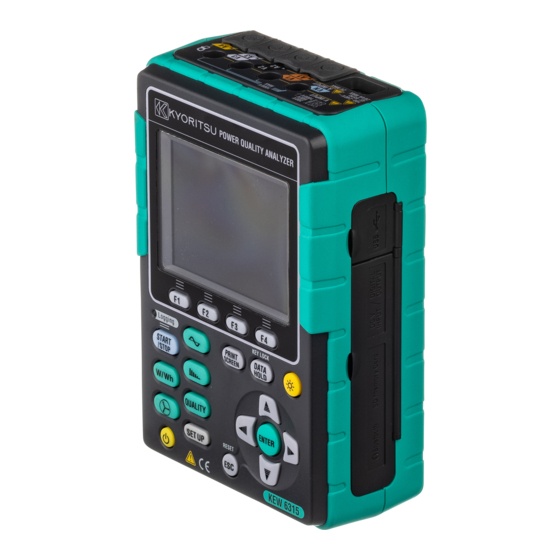
- Page 1 Power Quality Analyzer KEW6315...
-
Page 3: Table Of Contents
Contents KEW6315 Contents····································································································· 1 Unpacking Procedure ··················································································· 5 Safety warnings··························································································· 8 Chap. 1 Instrument overview ········································································ 11 1.1 Functional overview········································································ 11 1.2 Features ·······················································································13 1.3 Constructional drawing····································································14 1.4 Steps for measurement···································································15 Chap.2 Instrument layout ·············································································16 2.1 Display (LCD)/ Keys ·······································································16 2.2 Connector·····················································································17 2.3 Side face ······················································································18 2.4 Voltage test lead and Clamp sensor ··················································19... - Page 4 KEW6315 Contents 4.2 Power Supply················································································29 Battery····················································································29 Battery Mark on the LCD/ Battery level ········································30 How to install batteries ······························································31 Power cord connection······························································31 Power supply rating ··································································32 4.3 Placing / removing SD card ·····························································33 Inserting SD card······································································34 Removing SD card ···································································34 4.4 Voltage test leads and Clamp sensor connection···························35 4.5 Start KEW6305 ········································································36 Start-up Screen········································································36...
- Page 5 Contents KEW6315 Filter setting for Flicker measurement ··········································69 Target power factor for Capacitance calculation·····························70 5.4 Recording setting···········································································71 Settings for recording items························································72 Saved items·············································································73 Recording method ····································································74 Possible recording time ·····························································76 5.5 Other settings················································································77 Settings for system environment ·················································77 KEW6315 Setting ·····································································79 5.6 Saved data ···················································································82 To delete, transfer or format the recorded data ······························82 Type of the saved data ······························································87...
- Page 6 KEW6315 Contents 6.7 Power quality··············································································· 114 Factors impair power quality and symptoms································ 114 Displaying recorded events ······················································ 116 Displaying measured flicker values in list form····························· 120 Displaying trend graph of Pst, 1min ··········································· 121 Displaying changes of Plt························································· 122 Chap.7 Other functions ·············································································· 123 Chap.8 Device connection··········································································...
-
Page 7: Unpacking Procedure
Unpacking Procedure KEW6315 Unpacking procedure We thank you for purchasing our Power Quality Analyzer “KEW6315”. Please check the contents and instrument before use. Main unit KEW6315 :1 pce MODEL7255 :1 set Voltage test lead *red, white, blue, black: 1 pce for each (with alligator clips) Power cord MODEL7169 :1 pce... - Page 8 KEW6315 Unpacking Procedure 1. Main unit 2. Voltage test lead 3. Power cord 4.USB cord 5. Quick manual 6.CD-ROM 7. Battery 8. SD card 9. Carrying case M-8326-02 10. Input terminal plate 11. Cable marker KEW6315 - 6 -...
- Page 9 Unpacking Procedure KEW6315 12. Clamp sensor (depending on model purchased) 50A Type(ø24mm) M-8128 100A Type(ø24mm) M-8127 200A Type(ø40mm) M-8126 500A Type(ø40mm) M-8125 1000A Type(ø68mm) M-8124 13. Instruction manual for Clamp sensor 3000A Type(ø150mm) M-8129 1000A Type(ø110mm) M-8130 10A Type(ø24mm) M-8146 10A Type(ø40mm) M-8147 10A Type(ø68mm)
-
Page 10: Safety Warnings
KEW6315 Safety warnings Safety warnings This instrument has been designed, manufactured and tested according to IEC 61010-1: Safety requirements for Electronic Measuring apparatus, and delivered in the best condition after passing quality control tests. This instruction manual contains warnings and safety procedures which have to be observed by the user to ensure safe operation of the instrument and to maintain it in safe condition. - Page 11 Safety warnings KEW6315 DANGER equipped with the instrument will not work, and instrument damage or serious personal injury may occur. Verify proper operation on a known source before taking action as a result of the indication of the instrument. measurements on a circuit in which the electrical potential exceeds the following values. * 300V AC for CAT.
- Page 12 KEW6315 Safety warnings is large. Caution long time. is off. card or the instrument may be damaged. Confirm the SD card.) Otherwise, the saved data in the card may be lost or the instrument may be damaged. - Clamp sensor - - Treatment after use - the instrument.
-
Page 13: Chap. 1 Instrument Overview
1.1 Functional overview KEW6315 Chap. 1 Instrument overview Functional overview Start/ Stop Choose either “Quick start guide” or “Start now” to start recording. Can do simple and fast start-up setting by selecting “Quick start guide”. See “4.6 Recording procedures” (P.37) for further details. Inst/ Integration/ Demand Display the avg/ max/ min instantaneous values of current/ voltage/ active power/ apparent power/ reactive power. - Page 14 KEW6315 1.1 Functional overview Waveform Waveforms of voltage and current per CH are displayed on a graph. See “6.5 Waveform” (P.107) for further details. Harmonic Analysis Harmonic components of voltage and current per CH are displayed on a graph. See “6.6. Harmonics” (P.108) for further details. Power Quality (QUALITY) event Display voltage swell, dip, int, transient, inrush current Setting (SET UP)
-
Page 15: Features
1.2 Features KEW6315 1.2 Features This is a Clamp-type Power Quality Analyzer that can be used for various wiring systems. It can be used for simple measurements of instantaneous/ integration/ demand values, and also for analysis of harmonics and events related to power quality and for the simulation of power factor correction with capacitor banks. Moreover, it can display waveforms and vectors of voltage and current. -
Page 16: Constructional Drawing
KEW6315 1.3 Constructional overview 1.3 Constructional drawing Current input AC Voltage input Power cord Digital output (1 ch) to recorder or alarm Analog input (2 ch) from thermometer or illuminometer Size AA alkaline dry-cell battery (LR6) or Size AA Ni-MH rechargeable battery SD card KEW6315... -
Page 17: Steps For Measurement
1.4 Steps for measurement KEW6315 Steps for measurement Read through the operating instructions described in “Safety warnings” (P.8) before starting to use the instrument. Preparation Chap. 4: Getting started (P.27) Cord and Sensor Connection Clause 4.4: Voltage test leads and Clamp sensor connection (P.35) Turning on the instrument. -
Page 18: Chap.2 Instrument Layout
KEW6315 2.1 Display (LCD)/ Keys Chap.2 Instrument layout Display (LCD)/ Keys Display (LCD) Keys KEW6315 - 16 -... -
Page 19: Connector
2.2 Connector KEW6315 2.2 Connector AC Voltage Input Terminal (VN, V1, V2, V3) Current Input Terminal (A1, A2, A3, A4) Terminal Cover Power Connector AC Voltage Input Current Input Wiring configuration Terminal Terminal* Single-phase 2-wire (1-system) 1P2W×1 VN, V1 Single-phase 2-wire (2-system) 1P2W×2 VN, V1 A1, A2... -
Page 20: Side Face
KEW6315 2.3 Side face Side face < When the Connector cover is closed. > USB port cover SD slot cover Analog input/ Digital output cover < When the Connector cover is opened. > SD card slot USB port Analog input/ Digital output terminals KEW6315 - 18 -... -
Page 21: Voltage Test Lead And Clamp Sensor
2.4 Voltage test lead and Clamp sensor KEW6315 Voltage test lead and Clamp sensor <Alligator clip> * Attached to the top part of voltage test lead Barrier <Clamp sensor> Barrier Barrier is a mechanical safety part and provides protection against electrical shock and ensuring the minimum required air and creepage distances. -
Page 22: Chap.3 Basic Operations
KEW6315 3.1 Key operation Basic operations 3.1 Key operation PRINT SCREEN Function Save the displayed screen as BMP file. Execute the displayed function. DATA HOLD Key/ KEY LOCK Hold the readings on the display. * Measurement continues while the readings are being held on the display. Long press (at least 2 sec) disables all Keys to prevent operational errors. -
Page 23: Icons On The Lcd
3.2 Icons on the LCD KEW6315 Icons on the LCD Icon Status KEW6315 is operating with battery. This icon varies in 4 steps according to the battery power condition. KEW6315 is operating with AC power. Holding the display update. Keys are locked. Buzzer is off. -
Page 24: Symbols On The Lcd
KEW6315 3.3 Symbols on the LCD Symbols on the LCD Phase voltage Line voltage Current consumption lagging Active Reactive Apparent power power power regenerating leading Power lagging Frequency factor leading Analog input Analog input voltage at 1ch voltage at 2ch Phase lagging Neutral current... -
Page 25: Screens
Inst/ Integration/ Demand KEW6315 3.5 Screens Inst/ Integration/ Demand Switching screens Press the key to toggle the screens. W (Inst value) Wh (Integration value) Demand Customize Select and change the items to be displayed. Trend Changes of measured values are displayed on a graph. -
Page 26: Vector
KEW6315 Vector Vector Switching screens Wiring check Checked results will be displayed. Wiring diagram Diagram of the selected wiring is displayed. Waveform Switching screens KEW6315 - 24 -... -
Page 27: Harmonic Analysis
Harmonics KEW6315 Harmonics Switching screens Voltage, Linear, Overall display Current Power Logarithm Zoom List, Rate of content RMS value Phase angle Current Power - 25 - KEW6315... -
Page 28: Power Quality
KEW6315 Power quality Power quality Switching displayed items Flicker Event Settings Switching displayed items Toggle the screens with the Cursor Key. (right or left KEW6315 - 26 -... -
Page 29: Chap.4 Getting Started
Putting Input terminal plate on the Input terminal KEW6315 Getting started Preparation Putting Input terminal plate on the Input terminal Six Input terminal plates are supplied with this instrument. Choose one Plate which matches the standard cord colors where the instrument is used. Put the Plate to the Input terminal observing the orientation. * Clean the Input terminal before putting the Plate and confirm it isn’t wet. -
Page 30: Attaching Markers To Voltage Test Leads And Clamp Sensors
KEW6315 Attaching Markers to Voltage test leads and Clamp sensors Attaching Markers to Voltage test leads and Clamp sensors Attach Markers to the both ends of the Voltage test leads and Clamp sensors harmonized with the Input terminals. * Supplied Markers are 32 pcs in total : 4pcs each color (red, blue, yellow, green, brown, gray, black, white). -
Page 31: Power Supply
Battery KEW6315 Power Supply Battery KEW6315 operates with either an AC power supply or batteries. Capable of performing measurements in the event of AC power interruption, power to the instrument is automatically restored by the batteries installed in the instrument. Size AA alkaline dry-cell batteries (LR6) or size AA Ni-MH batteries can both be used. -
Page 32: Battery Mark On The Lcd/ Battery Level
KEW6315 Battery Mark on the LCD/ Battery level Battery Mark on the LCD/ Battery level Power supply icon changes as follows, and the battery icon varies according to the battery condition. Powered by AC 4-level Possible continuous measurement hours: - approx 3 hours with size AA alkaline batteries, and Powered by - approx 4.5 hours with size AA Ni-MH (1900mA/h) battery... -
Page 33: How To Install Batteries
How to install batteries KEW6315 How to install batteries: Follow the steps below and install batteries. Battery compartment Screw cover LR6: Size AA Alkaline battery Disconnect the power cord, voltage test leads and clamp sensors from the instrument, and power off the instrument. Loosen two Battery compartment cover-fixing screws and remove the Cover. -
Page 34: Power Supply Rating
KEW6315 Power supply rating Follow the procedure below, and connect the Power cord. Confirm that the instrument is powered off. Connect the Power cord to the Power connector on the instrument. * Connect another end of the Power cord to the outlet. * Getting KEW6315 started is possible 2 seconds after it is connected to a power source. -
Page 35: Placing / Removing Sd Card
4.3 Placing / removing SD card KEW6315 4.3 Placing / removing SD card Check the following points before using SD card. CAUTION turned up. If the card is inserted up-side-down, the SD card or the instrument may be damaged. card.) Otherwise, the saved data in the card may be lost or the instrument may be damaged. or the instrument may be damaged. -
Page 36: Inserting Sd Card
KEW6315 Inserting SD card Inserting SD card: Open the Connector cover. Insert the SD card into the SD card slot with the topside turned up. Then close the cover. Please use the instrument with the Connector cover closed unless it is not necessary. -
Page 37: Voltage Test Leads And Clamp Sensor Connection
4.4 Voltage test leads and Clamp sensor connection KEW6315 4.4 Voltage test leads and Clamp sensor connection Check the following before connecting the test leads and sensors. DANGER the Clamp sensor is not exceeded. parameters. under test. WARNING exposed metal parts. Follow the procedure below, and connect the Voltage test leads and Clamp sensors. -
Page 38: Start Kew6305
KEW6315 Start-up Screen Start KEW6315 Start-up Screen Hold down the POWER key until the following screen is displayed on the LCD. To power off the instrument, hold down the POWER key at least 2 seconds. Model name and software version will be displayed upon powering on the instrument. Stop using the instrument if it does not get started properly, and refer to “Chap. -
Page 39: Recording Procedures
Start of recording KEW6315 Recording procedures Start of recording Press the Key. Choose either “Quick start guide” or “Start now” to start recording. One can do the simple and fast start-up by selecting “Quick start guide”. Only the settings of wiring and recording are included in the “Quick start guide”. Press the key and adjust advanced settings if necessary. -
Page 40: End Of Recording
KEW6315 End of recording End of recording Press the Key. Data no. Recording method Items to be recorded Check the information about recording, or stop the recording. Items displayed on the LCD Data no. Data no. of the recorded data. It is also used as a folder name at data saving. Elapsed time The time that elapses while recording. -
Page 41: Start Measurement With "Quick Start Guide
Start measurement with “Quick start guide” KEW6315 Start measurement with “Quick start guide” Select the Select the Confirm the Check the test recording item wiring system connections environment (1) Select the item you want to record. * The number of selected items will have effect on file size and also on max recording time. - Page 42 KEW6315 Start measurement with “Quick start guide” Start Select the Select the Check the rec. interval rec. method selected method recording (6) Select a recording interval. * Selecting a short interval gets the file size large. In this case, a long period recording cannot be performed. See P.76.
- Page 43 Start measurement with “Quick start guide” KEW6315 (2) Wiring system Any of the following can be selected. Load Load 1P2W×1 1P3W×1 1P2W 1P3W Load 1P2W×2 1P2W 1P3W×2 Load Load 1P2W×3 1P2W 1P3W Load 1P2W×4 1P2W L1(R) L1(R) L1(R) L1(R) Load Load L2(S) L2(S)
- Page 44 KEW6315 Start measurement with “Quick start guide” (4)(5) Test Environment Check Switching screens Test environment check Select “ Start test ”and press the “ENTER” Wiring check button to start the test. The test result will be displayed on the screen. Test results of each item will be displayed.
- Page 45 Start measurement with “Quick start guide” KEW6315 NG judgment Wiring check Close the result display. Then, the blinking vectors and the values of NG items will be displayed. If everything is OK, the ideal vector diagram will be displayed in the lower left corner. Criteria of judgment and cause Check Criteria of Judgment...
- Page 46 KEW6315 Start measurement with “Quick start guide” Self-diagnosis If “NG” judgment is given frequently, there might be something wrong with the instrument. Stop using the instrument and refer to “Chap.11 Troubleshooting” (P.157). Sensor detection If the detection result is NG, each sensor type will be displayed in red. Criteria of judgment and cause Check Causes...
- Page 47 Start measurement with “Quick start guide” KEW6315 (8)(9) Setting for recording method The following explains how to set recording start date and time. Specify the recording start date and time. During the selected period, KEW6315 records data at the preset intervals. Example: When the date &...
- Page 48 KEW6315 Start measurement with “Quick start guide” Switching of displayed parameters Basically, the Cursor is used for selecting an item, the ENTER is for confirming the selection, and the is for canceling the alternation. Taking the procedures in “Quick Start Guide”...
-
Page 49: Chap.5 Settings
List of setting items KEW6315 Settings 5.1 List of setting items Settings for measurement condition and data saving are necessary prior to making measurements. Press the Key to enter into the SET UP mode and do the necessary settings. Settings consist of the following five categories. Use the to move between the categories. -
Page 50: Basic Setting
KEW6315 Basic setting Basic setting Press the Key. Use the Key to display the Basic setting screen. KEW6315 - 48 -... -
Page 51: Settings Of Wiring System
Settings of wiring system KEW6315 Settings of wiring system ”Basic wiring” Choose one according to the wiring system to be measured. Selection (1) 1P2W×1 (5) 1P3W×1 (7) 3P3W×1 (2) 1P2W×2 (6) 1P3W×2 (8) 3P3W×2 (3) 1P2W×3 (9) 3P3W3A (4) 1P2W×4 (10) 3P4W * Current terminals that are not used in the selected wiring system can be used to measure rms currents and harmonics. - Page 52 KEW6315 Settings of wiring system Wiring diagrams When the blue highlight is located at “Wiring”, you can check the wiring diagram of the selected wiring system with the key. The displayed diagram can be switched with key. Confirm. Cancel. KEW6315 - 50 -...
-
Page 53: Wiring Connection
Wiring connection KEW6315 Wiring connection Read the following precautions prior to wiring connection. DANGER measurements on a circuit in which the electrical potential exceeds the following values. * 300V AC for CAT. IV, 600V AC for CAT. III, 1000V AC for CAT. II them to the measured object or the power source. - Page 54 KEW6315 Wiring connection Clamp sensor direction for correct measurement: Load Arrow mark: Point towards load side. Power source * Reverse clamping switches the symbols (+/-) for active power (P). KEW6315 - 52 -...
-
Page 55: Settings Of Voltage Measurement
Settings of voltage measurement KEW6315 Settings of voltage measurement “Voltage range” Choose a desired voltage range. * For measurements according to IEC61000-4-30 Class S, set the range to “600V”. Selection 600V/1000V * Default setting is highlighted in gray. Move the blue highlight to “V Range”. Show the pull-down menu. - Page 56 KEW6315 VT/ CT VT/CT* * This setting belongs to Current measurement setting. DANGER measurements on a circuit in which the electrical potential exceeds the following values. * 300V AC for CAT. IV, 600V AC for CAT. III, 1000V AC for CAT. II the high voltage generated at the secondary side terminals.
- Page 57 Settings of voltage measurement KEW6315 ”Nominal voltage” Set the nominal voltage values applied from the measured object. Selection 50V - 600V(100V) * Default value is highlighted in gray. Move the blue highlight to “Nominal V”. Show the value entry window.* * A pop-up appears and show the effective range.
-
Page 58: Settings Of Current Measurement
KEW6315 Settings of current measurement Settings of current measurement “Clamp” : Clamp sensors for current measurement Select the model names of the connected sensors. If an optional sensor is used and set for “+Clamp”, an exceptional sensor can be set for 4ch. The rated current and the max conductor size are displayed in a pop-up while opening the list of sensor model names. - Page 59 Settings of voltage measurement KEW6315 ”Current range” Choose a desired current range. While “Record” is set at the “Recording Tab” to record the power quality events, “AUTO”* is not selectable. To enable auto-ranging at current range, select “Do not record” for “Event” in the REC Item.
-
Page 60: Settings Of External Input Terminal/ Reference Frequency
KEW6315 Settings of External input terminal/ reference frequency Settings of External input terminal/ reference frequency ”DC Range” Select a proper DC range according to the incoming DC voltage signals. Selection 100mV/ 1000mV/ 10V * Default setting is highlighted in gray. Move the blue highlight to “DC Range”. -
Page 61: Measurement Setting
5.3 Measurement setting KEW6315 5.3 Measurement setting Press the Key. Change the tabs to “Measurement”. Settings of demand measurement “Measurement cycle” Disable the demand measurement or set the demand measurement cycle in the preset recording period. When a demand measurement start, the measured demand values will be recorded at the selected measurement cycle. - Page 62 KEW6315 Settings of demand measurement ”Target value” Set the demand target value. Selection 0.001mW - 999.9TW(100.0kW) * Default setting is highlighted in gray. Move the blue highlight to “Target”. Show the value entry window.* * A pop-up appears and show the effective range. Enter the desired target value.
- Page 63 Settings of demand measurement KEW6315 ”Inspection cycle” The buzzer sounds when the predicted value exceeds the target value within the selected inspection cycle. The inspection cycle should be shorter than the demand measurement cycle. The relations between the measurement and inspection cycles are as follows. Measurement cycle Inspection cycle 10 min/ 15 min...
-
Page 64: Outline Of Demand Measurement Concept
KEW6315 Outline of demand measurement concept Outline of demand measurement concept In such a contract the electricity tariff rates (i.e. for kWhr units) are based upon the consumer’s maximum power demand. The maximum demand is the maximum of average powers recorded over a 30min interval. Assuming the max target demand to be 500kW, the average power during Measurement cycle 1 is fine, but the power consumption for the first 15 min of Measurement cycle 2 is 600kW. -
Page 65: Settings For Harmonic Analysis
Settings for Harmonic analysis KEW6315 Settings for Harmonic analysis “THD calculation” THD stands for ”Total Harmonic Distortion”. Select “THD-F” to calculate the total harmonics distortion based on the basic wave and “THD-R” to do the calculation based on all rms values. Selection THD-F (based on basic wave)/ THD-R (based on all rms values) * Default setting is highlighted in gray. - Page 66 KEW6315 Settings for Harmonic analysis ”Edit allowable range” Set the EMC allowable range (rate of content) for harmonics per order. The edited ranges are displayed as bar graph on the graph of harmonics. Selection Default/ can be customized (V/ A) * Default setting is highlighted in gray.
-
Page 67: Threshold Setting For Power Quality (Event)
Threshold setting for Power quality (Event) KEW6315 Threshold setting for Power quality (Event) Press the (OFF/ ON) to disable or enable the “threshold value” entry. If “OFF” is selected, the item will not be recorded even the threshold value is set for it. The threshold value used during the previous measurement is displayed by pressing the (ON) key. - Page 68 KEW6315 Threshold setting for Power quality (Event) “Transient”: Over-voltage (Impulse) Set an instantaneous voltage value as a threshold for the transient event. The following selection range varies depending on the selected VT ratio. Selection ±50 to ±2200Vpeak against the nominal voltage (300%) * Default setting is highlighted in gray.
- Page 69 Threshold setting for Power quality (Event) KEW6315 “SWELL”: Instantaneous voltage rise Set the threshold value (rms voltage in one cycle) for swell in percentage of the nominal voltage. The following selection range varies depending on the selected VT ratio. The preset hysteresis has an effect on this threshold value.
- Page 70 KEW6315 Threshold setting for Power quality (Event) “DIP”: Instantaneous voltage drop Set the threshold value (rms voltage in one cycle) for dip in percentage of the nominal voltage. The following selection range varies depending on the selected VT ratio. The preset hysteresis has an effect on this threshold value.
-
Page 71: Filter Setting For Flicker Measurement
Filter setting for Flicker measurement KEW6315 Filter setting for Flicker measurement “Filter coefficient” Set a proper filter coefficient according to the nominal voltage for accurate flicker measurements. Select the values of nominal voltage, nominal frequency and filter coefficient values appropriate to the actual measured object. -
Page 72: Target Power Factor For Capacitance Calculation
KEW6315 Target power factor for Capacitance calculation Target power factor for Capacitance calculation “Target power factor” Set a target power factor for capacitance calculation. The power factor gets influenced badly if inductive loads, such as motors, are connected to the power supply because current phases lag behind the voltage phases in this case. -
Page 73: Recording Setting
5.4 Recording setting KEW6315 5.4 Recording setting Press the Key. Change the tabs to “Recording”. - 71 - KEW6315... -
Page 74: Settings For Recording Items
KEW6315 Settings for recording items Settings for recording items The possible recording time on SD cards or the internal memory varies depending on the number of the recorded items and the preset intervals. Select “Do not record” for the items which are not necessary to be recorded to secure a longer recording time. -
Page 75: Saved Items
Saved items KEW6315 Saved items The following data measured on each CH will be saved according to the selected recording method. Saved items are depending on the selected recording method and wiring system. Meas./ Rec. setting REC file REC item Power +Harmonics +Event... -
Page 76: Recording Method
KEW6315 Recording method Recording method “Interval” Set the interval to record the measured data on the SD or internal memory. Seventeen different intervals are available, but it cannot be set to a longer time than the demand measurement cycle. The preset recording interval may be changed automatically according to the selected demand measurement cycle. - Page 77 Recording method KEW6315 “Start” Select the method to start recording. Selection Manual/ Constant rec./ Time period rec. * Default setting is highlighted in gray. Move the blue highlight to “Start”. Show the pull-down menu. Select a desired recording start method. Confirm.
-
Page 78: Possible Recording Time
KEW6315 Possible recording time “Time period recording” Measured data will be recorded at the preset interval for the specified time period of the selected period. When the specified time comes, a recording will start and end automatically; such a recording cycle will be repeated everyday during the specified period. -
Page 79: Other Settings
5.5 Other settings KEW6315 5.5 Other settings Press the Key. Change the tabs to “Others”. Settings for system environment “Language” Select the language to be displayed. Selection Japanese/ English * Default setting is highlighted in gray. Changes made by user will remain after system reset. Move the blue highlight to “Language”. - Page 80 KEW6315 Settings for system environment “Date format” Select a desired date display format. The selected date format will be reflected to the date display on the screen and on each setting window. Selection YYYY/ MM/ DD / MM/ DD/ YYYY / DD/ MM/ YYYY * Default setting is highlighted in gray.
-
Page 81: Kew6315 Setting
KEW6315 Setting KEW6315 KEW6315 Setting “Time” Adjust and set the internal system clock. Selection dd/ mm/ yyyy hh:mm * The selected date format has an effect on this setting. Move the blue highlight to “Time”. Show the value entry window. Adjust the time and date. - Page 82 KEW6315 KEW6315 Setting “Buzzer” Keypad sounds can be muted. The warning buzzer for demand judgment or low battery voltage sounds even “OFF” is selected. Selection On/ Off * Default setting is highlighted in gray. Move the blue highlight to “Buzzer”. Show the pull-down menu.
- Page 83 KEW6315 Setting KEW6315 “Backlight” This setting can turn off the backlight automatically when the prescribed time passes after the last key operation. The backlight will be turned off in 2 min after the last operation while KEW6315 is operating with batteries.
-
Page 84: Saved Data
KEW6315 5.6 Saved data 5.6 Saved data Press the Key. Change the tabs to “Saved data”. Save the “ ”: Measurement data, “ ”: Print screen” and “ ”: Setting data” on the “ ”SD card or in the “ ”... - Page 85 To delete, transfer or format the recorded data KEW6315 “Delete data” Show the list of the recorded data, and then select unnecessary data. Icons on the screen means: : SD card, : Internal memory, Measured data, : Print screen, : Setting data Data are not listed in time sequence.
- Page 86 KEW6315 To delete, transfer or format the recorded data “Space” Storage media information can be checked with the Key. Press the Key to close the information window. Displayed items Selection Total size Total memory capacity Capacity Free size Capacity of free space Estimated possible recording time if the parameters to be Power only recorded are limited to power-related ones only.
- Page 87 To delete, transfer or format the recorded data KEW6315 “Transfer data” Select the data you want to transfer from the “ ”: internal memory to the SD card “ ”. Data files which can be transferred are: “ ”: Measurement data, “ ”: Print screen, “...
- Page 88 KEW6315 To delete, transfer or format the recorded data “BACK” To return to the “Saved data” screen, press the Key. “Format” Format the “ ”: SD card or “ ”: Internal memory. Data are not listed in time sequence. The recorded date and time are displayed to the right of file name.
-
Page 89: Type Of The Saved Data
Type of the saved data KEW6315 Type of the saved data Data file handling The file name will be assigned automatically. File no. is kept and saved, even after powering off the instrument, until the system is reset. The file number will increase until it exceeds the max file number. If a file with the same file name already exists, the files in the data folder will be saved as another name with a different file number. - Page 90 KEW6315 Type of the saved data “Data folder” New folder will be created per measurement to save the interval and power quality data. Folder / KEW 0000 name: Dest. code Data No. S:SD card (0000-9999) M:Internal memory “Interval data” KEW6315 setting File name 0000 .KEW...
-
Page 91: Kew6315 Settings And Data Loading
KEW6315 settings and Data loading KEW6315 KEW6315 settings and Data loading Select a desired operation. Confirm. “Save settings” Save the “ ”: Setting data on the “ ”: SD card or in the “ ”: internal memory. Data are not listed in time sequence. - Page 92 KEW6315 KEW6315 settings and Data loading “Space” Storage media information can be checked with the Key. Press the Key to close the information window. Please refer to “Space” (P. 84) for further details. “BACK” To return to the “Saved data” screen, press the Key.
- Page 93 KEW6315 settings and Data loading KEW6315 “Read settings” Read the “ ”: Setting data from the “ ”: SD card or from the “ ”: internal memory. Data are not listed in time sequence. The recorded date and time are displayed to the right of file name. As for the data which are previously transferred from the internal memory to an SD card, the displayed time means when the data were transferred.
-
Page 94: Chap. 6 Displayed Items
KEW6315 Instantaneous value “W” Chap. 6 Displayed Items Instantaneous value “W” Press the Key. Display the screen for “W”: Instantaneous value. List display of the measured values “List” (/Zoom) e.g.) Instantaneous values measured under 3P3W3A+1A (Three-phase Three-wire + Current (optional sensor)) Measured at 1CH Measured at 2CH Measured at 3CH... - Page 95 List display of the measured values KEW6315 Symbol displayed on the LCD Phase voltage Line voltage Current consumption Lagging Active Reactive Apparent power power power regenerating leading Lagging Power Frequency factor leading Analog input Analog input Voltage at 1ch Voltage at 2ch Lagging V/A Phase Neutral current...
- Page 96 KEW6315 List display of the measured values “Switching the displayed systems” Press the key and switch the displayed systems. Items displayed in a screen depend on the selected wiring configuration and the number of systems. The dotted lines represent the space of each display area.
- Page 97 List display of the measured values KEW6315 3P3W3A (Three-phase 3-wire) 3P4W (Three-phase 4-wire) Measured Measured Measured Measured Measured Measured values on values on values on values on values on values on (V23/A2) (V31/A3) (V12/A1) (V1/A1) (V2/A2) (V3/A3) Sum of 1, 2 and 3ch Sum of 1, 2 and 3ch “Switching the type of displayed values”...
-
Page 98: Zoom Display
KEW6315 Zoom display Zoom display Example: 8-split screen Displayed item Type of value: Inst/ AVG…. Select 4 or 8 values and display the values on one screen. The displayed text will be enlarged so it is easy to see. ”Displayed items” Select the items to be displayed in each column. -
Page 99: Displaying Trend Graph
Displaying Trend graph KEW6315 ”Type of value” Any of the following values can be displayed in each column. Inst: Instantaneous value, or AVG: Average value, MAX: Maximum value or MIN: Minimum value within the selected interval. If the selected interval is “1 sec”, Inst, Avg, Max and Min values will be the same since the display update is also “1 sec”. - Page 100 KEW6315 Displaying Trend graph The following example shows 1P3W-2 (Single-phase 3-wire, 2-system). ”Change the items displayed on Trend graph” Press the key and change the items displayed on the trend graph. values will be displayed on the trend graph. “List display” Press the (List) to show all the values on a list.
-
Page 101: Changing Displayed Items And Display Position
Changing displayed items and display position KEW6315 Changing displayed items and display position Present displayed items After the change The displayed items can be changed to any desired ones. Move the blue highlight to the item you want to change. Show the pull-down menu. -
Page 102: Integration Value "Wh
KEW6315 6.2 Integration value “Wh” Integration value “Wh” Press the Key. Display the screen for “Wh”: Integration value. e.g.) 1P3W-2 (Single-phase Three-wire, 2-system) Elapsed time : Total amount :sum per system Power used in the certain period is displayed as integral power consumption. Integral power consumption is used to calculate electricity tariffs or to control the power consumption. - Page 103 6.2 Integration value “Wh” KEW6315 e.g.) 1P3W-2 (Single-phase Three-wire, 2-system) “Change the displayed systems” Press the Key to switch the displayed systems. Please refer to “Setting of wiring system” (P. 49) in this manual. ”Change the displayed chs” Press the Key to switch the displayed channels.
-
Page 104: Demand
KEW6315 6.3 Demand ”Demand” Press the Key. Display the screen for demand value. Change the screens to display the demand measurement results in various forms. Showing the measured values Move the blue highlight to “Meas.”. The demand is the average powers recorded over a certain period. When the estimated value exceeds the target value during demand measurements, the warning buzzer sounds at the inspection cycles. -
Page 105: Shifts In Specific Period
Shifts in specific period KEW6315 Shifts in specific period Items displayed on the LCD Remaining time Demand interval is counted down. (time left) Percentage of the present value against the target value. DEM P Present value is displayed. Target value Percentage of the predicted value against the target value. -
Page 106: Demand Change
KEW6315 Demand change Demand change Cursor Scroll bar Press the Key to move the cursor and to scroll the graph to right and left. The white bar shows the percentage of hidden pages and the dark orange bar shows the percentage of the present displayed page. -
Page 107: Vector
6.4 Vector KEW6315 Vector Press the Key. e.g.) 3P4W Vector display Measured values V: rms voltage* /Phase angle* A: rms current / Phase angle* For 3P3W3A, rms line voltages are displayed. Phase angled is displayed: using Phase of V1 as the base (0 Phase angle (Leading) Vector display: -0°... - Page 108 KEW6315 6.4 Vector e.g.) Vector of 3P4W: ”V x desired magnification” : toggle the line lengths of voltage vector. *time(s) ”A x desired magnification” : toggle the line lengths of current vector. *time(s) “Diagram” Press the (Diagram) Key to show the wiring diagram for the selected wiring configuration. Please refer to “Wiring diagram”...
-
Page 109: Waveform
6.5 Waveform KEW6315 Waveform Press the Key. e.g.) Waveform of 1P3W-2 (Single-phase 3-wire, 2-system): Measured values V: rms voltage* A: rms current Colored waveforms For 3P3W3A, rms line per ch voltages are displayed. Voltage and current waveforms are displayed: for 10 cycles max. at 50Hz, for 12 cycles max. at 60Hz. When changing the screens for “Waveform”, waveforms are displayed in the max scale automatically. -
Page 110: Harmonics
KEW6315 6.6 harmonics ”A x desired magnification” : toggle the magnifications of current waveform (vertical). *time(s) ”t x desired magnification” : toggle the magnifications of time axis (horizontal). *time(s) “full scale : Restore all the changed magnification settings and automatically select the appropriate magnification. - Page 111 Displaying harmonics on the bar graph KEW6315 Bar graph display e.g.) “Linearity” is displayed in “Full-scale”. Rate of content Harmonics analysis: up to 50 order In the above example, “Linear” and “full-scale” are selected. In this case, the upper limit of the rate of content is “100%”...
- Page 112 KEW6315 Displaying harmonics on the bar graph e.g.) 3P4W (Three-phase 4-wire) : with “LOG” and “Zoom”. Exceeding the axis value Max value Exceeding the threshold Graph color Allowable range Items displayed on the graph Displayed when the rate of harmonics content of each order is more than 10%. Exceeding The rate of harmonics content of the 1st basic waveform is “100%”, therefore, the axis value...
- Page 113 Displaying harmonics on the bar graph KEW6315 “Change the displayed chs” Press the Key to change the displayed chs. The details about the relation between the wiring configuration and ch are described in “Settings of wiring system” (P.49). “List”/”Graph” Press the Key to display voltage/ current/ power harmonics, from 1 to 50 order, in list or...
-
Page 114: Displaying The List Of Harmonics
KEW6315 Displaying the list of harmonics Displaying the list of harmonics Press the (List) Key to display the list of harmonics. e.g.) “P: Power harmonics” and “Power” of 1P3W-2 (Single-phase 2-wire, 2-system) are listed. Rms values, rate of content and phase angle of voltage/ current/ power harmonics, from 1 to 50 , can be displayed in list form respectively. - Page 115 Displaying the list of harmonics KEW6315 ”Change the displayed harmonics orders” Press the Key to scroll the page vertically. ”Graph”/ ”List” Press the Key to display voltage/ current/ power harmonics, from 1 to 50 order, in list or graphic form. Only the rate of harmonics content can be checked on graph display screen, ”Rate of content”/”Phase angle”/ RMS value (Power)”...
-
Page 116: Power Quality
KEW6315 6.7 Power quality Power quality Press the Key to display Power quality screen. Factors impair power quality and symptoms Power quality Waveform Symptom Adverse effect Burnout of capacitors and Inverter and Thyristor circuits reactors, buzzes from (phase-control circuit) are used transformers, malfunction for the control circuit of general Harmonics... - Page 117 Factors impair power quality and symptoms KEW6315 Power quality Waveform Symptom Adverse effect Damage to a power source Transient, Contact failure at a circuit or reset of the device may Over-voltage breaker, magnet or relay. occur due to a drastic (impulse) voltage fluctuation (spike).
-
Page 118: Displaying Recorded Events
KEW6315 Displaying recorded events Displaying recorded events Press the (Event) Key to display the list of the recorded events. Measured values Symbol indicating event type Items and symbols displayed on the LCD Start Swell Symbol Transient Inrush current Instantaneous values recorded at the detection of the start and end of the event. If the occurred event terminates in quite short period, the value measured at the end of the event may not be displayed. - Page 119 Displaying recorded events KEW6315 Measurement of Swell/ Dip/ INT/ Inrush current Each event will be detected with the r.m.s. values in one gapless waveform and with a half-wave over- lapping. The beginning of the waveform where the first event is detected is regarded as the start of the event.
- Page 120 KEW6315 Displaying recorded events Detection of Transient Voltage waveforms will be monitored at approx 40ksps, gapless, to calculate and check for transient event every 200ms. The beginning of the 200ms period where the first transient is detected is regarded as the start of the event.
- Page 121 Displaying recorded events KEW6315 ”Change the displayed area” Press the Key to scroll the page vertically. “Flicker” Press the (Flicker) Key to display the recorded flicker values. Details are described in “Displaying measured flicker values in list form” (P. 120). ”Event detection”...
-
Page 122: Displaying Measured Flicker Values In List Form
KEW6315 Displaying measured flicker values in list form Displaying measured flicker values in list form Press the (Flicker) Key. Press the Key to change the displays: V: List display/ Pst(1min): Trend graph/ Plt: Transitional change. Time left If variable loads, such as arc furnace, are connected, voltages may vary and cause changes in illumination levels. -
Page 123: Displaying Trend Graph Of Pst, 1Min
Displaying trend graph of Pst, 1min KEW6315 Displaying trend graph of Pst, 1min Latest Pst,1min Pst,1min Max values Elapsed time The “Pst, 1min” measured in the recent 120 min is displayed on the trend graph. Items displayed on the LCD Pst,1min The latest Pst (1 min) Max “Pst, 1min”... -
Page 124: Displaying Changes Of Plt
KEW6315 Displaying changes of Plt Displaying changes of Plt Cursor Scroll bar Press the Key to move the cursor or to scroll the page to right and left. The black bar shows the percentage of hidden pages and the dark orange bar shows the percentage of the present displayed page. -
Page 125: Chap.7 Other Functions
Chap. 7 Other functions KEW6315 Chap. 7 Other functions “Data hold” Display update can be disabled by pressing the “DATA HOLD” Key. The “ ” icon will appear while display update is disabled. The icon will disappear and display update will be enabled by pressing the “DATA HOLD”... - Page 126 KEW6315 Chap. 7 Other functions “Auto-ranging” (Current range) Current ranges of each sensor are automatically switched according to the measured rms currents. This function does not work while recoding the power quality events. A range shifts to one upper range when the input exceeds 300%peak of each range and shifts to one lower range when the input drops under 100%peak of each range.
-
Page 127: Chap.8 Device Connection
8.1 Data transfer to PC KEW6315 Chap. 8 Device connection 8.1Data transfer to PC Data in the SD card or the internal memory can be transferred to PC via USB or SD card reader. Transfer to PC via: Card reader Internal memory data (file) --------- : It is recommended to transfer the large data by use of SD card since transferring large data files by... -
Page 128: Using Bluetooth
KEW6315 8.2 Using Bluetooth® function ® Using Bluetooth function ® Measuring data can be checked on android devices in real-time via Bluetooth communication. It is necessary ® ® to enable Bluetooth function prior to using Bluetooth communication. (Setting No. 26: Bluetooth) ®... - Page 129 Connection to input/ output terminals KEW6315 Open the Connector cover. Press the rectangular protrusion above a terminal with a flat-blade screw driver, and insert a signal wire. Remove the driver and fix the wire. Flat-blade screwdriver Signal wire ”Input terminal” For monitoring the voltage output signals of Thermo sensors.
-
Page 130: Getting Power From Measured Lines
KEW6315 8.4 Getting power from measured lines Getting power from measured lines If it is difficult to get power from an outlet, KEW6315 operates with power from the measured line by using Power supply adapter MODEL8312 and voltage test leads. DANGER either of them belongs to will be applied. -
Page 131: Chap. 9 Pc Software For Setting And Data Analysis
Chap. 9 PC software for setting and data analysis KEW6315 Chap. 9 PC software for setting and data analysis The special software “KEW Windows for KEW6315” for data analysis and for making KEW6315 settings is available. * Automatic creation of graph and list from recorded data. Uniform management of setting and recorded data acquired from multiple devices. -
Page 132: Chap.10 Specification
KEW6315 10.1 Safety requirements Chap. 10 Specification 10.1Safety requirements Location for use : In door use, Altitude up to 2000m Temperature & humidity range : 23ºC±5ºC, Relative humidity 85% or less (no condensation) (guaranteed accuracy) Operating Temperature & : 0ºC to 45ºC, Relative humidity 85% or less (no condensation) humidity range Storage Temperature &... - Page 133 10.2 General specification KEW6315 Backlight (Press the LCD Key to turn off, press any key other than “Power” to turn on.) PQ measurement : IEC 61000-4-30 Ed.2 Class S Dimension : 175(L)×120(W)×68(D)mm Weight : approx. 900g (including batteries) Accessories : V test leads MODEL7255 with alligator clip··...
- Page 134 KEW6315 10.2 General specification Real-time OS This Product uses the Source Code of T-Kernel under T-License granted by the T-Engine Forum (www.t-engine.org) Portions of this software are copyright (c) 2010 The FreeType Project (www.freetype.org). All rights reserved. External communication function : USB * USB cable length: 2m max.
-
Page 135: Measurement Specification
10.2 General specification KEW6315 Data storage location : Internal FLASH memory Storage capacity 4MB (Data storage capacity: 3,437,500byte) Max data size 14,623byte/data (max: 234 data) 3P3W-2/1P3W-2 (Power + Harmonics) Max number of saved file 3 * Number of times that you can start a measurement. Icon display When the internal memory is available, the “... -
Page 136: Items Measured At Instantaneous Measurement
KEW6315 Items measured at Instantaneous measurement Items measured at Instantaneous measurement Frequency f [Hz] Displayed digit 4-digit Accuracy ±2dgt (40.00Hz - 70.00Hz, V1 Range 10% - 110%, sine wave) Display range 10.00 - 99.99Hz Input source (fix) 10-sec average frequency f10 [Hz] Displayed digit 4-digit * e.g. - Page 137 Items measured at Instantaneous measurement KEW6315 R.M.S. Current A [Arms] Range MODEL8128 (50A) :5000m/50.00A/AUTO MODEL8127 (100A) :10.00/100.0A/AUTO MODEL8126 (200A) :20.00/200.0A/AUTO MODEL8125 (500A) :50.00/500.0A/AUTO MODEL8124/30 (1000A) :100.0/1000A/AUTO MODEL8141/8142/8143 (1A) :500.0mA MODEL8146/8147/8148 (10A) :1000m/10.00A/AUTO MODEL8129 (3000A) :300.0/1000/3000A Displayed digit 4-digit Effective input 1% - 110% of each Range (rms) and 200% of Range (peak) range Display area...
- Page 138 KEW6315 Items measured at Instantaneous measurement Active power P [W] Range Current 8128 8127 8126 Voltage 50.00A 5000mA 100.0A 10.00A 200.0A 20.00A 1000V 50.00k 5000 100.0k 10.00k 200.0k 20.00k 600.0V 30.00k 3000 60.00k 6000 120.0k 12.00k Current 8125 8124/30 8146/47/48 Voltage 500.0A 50.00A...
-
Page 139: Items To Be Calculated
Items to be calculated KEW6315 Items to be calculated Apparent power S [VA] Range Same as active power. Displayed digit Same as active power. Accuracy ±1dgt against each calculated value (for sum : ±3dgt) Sign No polarity indication Equation ×A when P >S regarding P... - Page 140 KEW6315 Items to be calculated Power factor: PF Display range -1.000 to 0.000 to 1.000 Accuracy ±1dgt against each calculated value (for sum : ±3dgt) : leading phase Sign (no sign) : lagging phase Harmonics reactive power is calculated per ch, and the polarity sign of the reversed basic waveform is displayed.
- Page 141 Items to be calculated KEW6315 Current unbalance ratio Aunb [%] Displayed digit 5-digit Display range 0.00% to100.00% Wiring 3P3W, 3P4W Equation Iumb * The 1st order components of harmonic current are used. * For 3P4W system, phase voltages are converted to line voltages for calculation.
-
Page 142: Items Measured At Integration Measurement
KEW6315 Items measured at Integration measurement Items measured at Integration measurement Power consumption (if P>0 Active power energy +WP [Wh] Displayed digit 6-digit, Unit: m, k, M, G, T (harmonized with Display area 0.00000mWh - 9999.99TWh (harmonized with * “OL” is displayed when the display area is exceeded. Equation h: integration period (3600 sec), c: Measurment channel, i: Data point no. - Page 143 Items measured at Integration measurement KEW6315 Reactive power energy +WQ [Varh] Displayed digit 6-digit, Unit: m, k, M, G, T (harmonized with Display area 0.00000mvarh - 9999.99Tvarh (harmonized with * “OL” is displayed when the display area is exceeded. Equation Leading phase Lagging...
- Page 144 KEW6315 Items measured at Integration measurement Apparent power energy -WS[VAh] Displayed digit 6-digit, Unit: m, k, M, G, T (harmonized with Display area 0.00000mVAh - 9999.99TVAh (harmonized with * “OL” is displayed when the display area is exceeded. Equation h: integration period (3600 sec), c: Measurment channel, i: Data point no. 1P2W-1 to 4 , -WS , -WS...
-
Page 145: Items Measured At Demand Measurement
Items measured at Demand measurement KEW6315 Items measured at Demand measurement Target value (DEM Target Displayed digit 4-digit Unit m, k, M, G, T Display range 0.000mW(VA) - 999.9TW(VA) *according to the selected values Predicted value (DEM Guess Displayed digit 6-digit Unit m, k, M, G, T (depending on DEM... -
Page 146: Items Measured At Harmonics Measurement
KEW6315 Items measured at Harmonics measurement Items measured at Harmonics measurement Meas. system : Digital PLL synchronization Meas. method : Analyze harmonics, and then add and display the inter-harmonics components adjacent to the integral order of the analyzed harmonics Effective frequency range : 40 - 70Hz Order analysis : 1 - 50th... - Page 147 Items measured at Harmonics measurement KEW6315 R.m.s. harmonics current Ak [Arms] Range Same as r.m.s. current Displayed digit Same as r.m.s. current Same as r.m.s. current Display range * Rate of content: 0.0% - 100.0% (percentages to the basic wave) Complied with IEC61000-4-7, IEC61000-2-4 Meas.
- Page 148 KEW6315 Items measured at Harmonics measurement Harmonics reactive power Qk [var] (used for internal calculation only) Equation ×A ×A c(10k)r c(10k)i c(10k)i c(10k)r c: Measurement channel: A , k: Harmonics of each order r: Real number after FFT conversion, i: Imaginary number after FFT conversion Measurement cycle in this equation is 10-cycle.
- Page 149 Items measured at Harmonics measurement KEW6315 Harmonics voltage total distortion factor THDVR [%] Displayed digit 4-digit Display range 0.0% - 100.0% Equation c: Meas. channel V: Harmonics voltage THDVR k: Harmonics of each order 1P2W-1 to 4 THDVR 1P3W-1 to 2 THDVR THDVR 3P3W-1 to 2...
- Page 150 KEW6315 Items measured at Harmonics measurement Displayed digit 4-digit Display range 0.0º to ±180.0º Equation c: Measurement channel 1k , 2k , 3k , A: Harmonics current k:Harmonics of each order r: Real number after FFT conversion, i: Imaginary number after FFT conversion Displayed digit 4-digit Display range...
-
Page 151: Items Measured At Power Quality Measurement
Items measured at Power quality measurement KEW6315 Items measured at Power quality measurement Voltage transient Meas. system Displayed digit 4-digit Effective 50V - 2200V (DC) input range Display range 50V - 2200V (DC) Accuracy 0.5%rdg * at 1000V (DC) Input impedance Threshold value Absolute peak voltage value Detection channel (ch) - Page 152 KEW6315 Items measured at Power quality measurement Inrush current Range Same as r.m.s. current Displayed digit Same as r.m.s. current Effective Same as r.m.s. current input range Display range Same as r.m.s. current Crest factor Same as r.m.s. current Input impedance Same as r.m.s.
- Page 153 Items measured at Power quality measurement KEW6315 Flicker Displayed Time left: Counted down time until a Pst calculation completes. items r.m.s. voltage per half-wave, 1 sec average Pst(1min): Flicker value for 1 min (Pst ref. value) Pst: Severity of short term flicker (10 min) Plt: Severity of long term flicker (2 hours) Max Pst:...
-
Page 154: Specification Of Clamp Sensor
KEW6315 10.4 Specification of Clamp sensor 10.4 Specification of Clamp sensor <MODEL8128 > <MODEL8127 > <MODEL8126 > AC 5Arms AC 100Arms AC 200Arms Rated current [Max. AC50Arms(70.7Apeak)] (141Apeak) (283Apeak) 0 - 50mV (AC 50mV/AC 5A) AC0 - 500mV AC0 - 500mV Output voltage [Max.AC 500mV/AC50A]:10mV/A (AC500mV/AC100A):5mV/A... - Page 155 10.4 Specification of Clamp sensor KEW6315 <MODEL8125 > <MODEL8124 > Rated current AC 500Arms (707Apeak) AC 1000Arms (1414Apeak) AC0 - 500mV AC0 - 500mV Output voltage (AC500mV/500A):AC 1mV/A (AC500mV/1000A):0.5mV/A Measuring range AC0 - 500Arms AC0 - 1000Arms Accuracy ±0.5%rdg±0.1mV (50/60Hz) ±0.5%rdg±0.2mV (50/60Hz) (sine wave input) ±1.0%rdg±0.2mV (40Hz - 1kHz)
- Page 156 KEW6315 10.4 Specification of Clamp sensor <KEW8129 > <KEW8130 > 300A Range: AC 300 Arms( 424Apeak) 1000A Range: AC 1000 Arms(1414Apeak) AC 1000 Arms(1850Apeak) 3000A Range: AC 3000 Arms(4243Apeak) 300A Range: AC0 - 500mV(AC500mV/AC 300A):1.67mV/A AC0 - 500mV 1000A Range: AC0 - 500mV(AC500mV/AC1000A):0.5mV/A (AC500mV/AC1000A):0.5mV/A 3000A Range: AC0 - 500mV(AC500mV/AC3000A):0.167mV/A 300A Range:...
- Page 157 10.4 Specification of Clamp sensor KEW6315 <MODEL8141 > <MODEL8142 > <MODEL8143 > Rated current AC1000mArms Output voltage AC0 - 100mV(AC100mV/AC1000mA) Measuring range AC0 - 1000mArms Accuracy ±1.0%rdg±0.1mV (50/60Hz) (sine wave input) ±2.0%rdg±0.1mV (40Hz - 1kHz) Phase ------------- characteristics Temp. & humidity range (guaranteed 23±5ºC, relative humidity 85% or less (no condensation) accuracy)
- Page 158 KEW6315 10.4 Specification of Clamp sensor <KEW8146 > <KEW8147 > <KEW8148 > AC 30Arms (42.4Apeak) AC 70Arms (99.0Apeak) AC 100Arms (141.4Apeak) AC0 - 1500mV(AC50mV/A) AC0 - 3500mV(AC50mV/A) AC0 - 5000mV(AC50mV/A) AC0 - 30Arms AC0 - 70Arms AC0 - 100Arms 0 - 15A 0 - 40A 0 - 80A ±1.0%rdg±0.1mV (50/60Hz)
-
Page 159: Chap. 11 Troubleshooting
11.1 General troubleshooting KEW6315 Troubleshooting 11.1 General troubleshooting When defect or breakdown of the instrument is suspected, check the following points first. If your problem is not listed in this section, contact your local Kyoritsu distributor. Symptom Check When operating with an AC power supply: Instrument cannot be powered on. -
Page 160: Error Messages And Actions
KEW6315 11.2 Error messages and actions Symptom Check Data cannot be saved on the SD card. hardware. Download and setting cannot be done via USB communication. for KEW6315” and check the connected devices are displayed or not. If the devices are not displayed, the USB driver might not be installed correctly. - Page 161 11.2 Error messages and actions KEW6315 the instrument or the sensor. Message Detail & Action Battery level is low. batteries with new ones. * Size AA Alkaline battery (LR6) or Powering off… fully-charged Size AA Ni-MH battery x 6pcs See “How to install batteries” (P. 31). the saved files.
- Page 162 KEW6315 11.2 Error messages and actions Message Detail & Action New sensor is detected. Recheck the basic setting for SET during the previous test. Modify the settings of clamp sensor UP before measurements. directly from the “Basic setting” or press the “Detect” key. Sensor connection is not correct.
- Page 163 DISTORIBUTOR Kyoritsu reserves the rights to change specifications or designs described in this manual without notice and without obligations. www.kew-ltd.co.jp 05-12 92-2161...
Need help?
Do you have a question about the KEW6315-03 and is the answer not in the manual?
Questions and answers