Sign In
Upload
Download
Table of Contents
Contents
Add to my manuals
Delete from my manuals
Share
URL of this page:
HTML Link:
Bookmark this page
Add
Manual will be automatically added to "My Manuals"
Print this page
×
Bookmark added
×
Added to my manuals
Manuals
Brands
Airwell Manuals
Air Conditioner
FLO 7 N
Technical manual
Airwell FLO 7 N Technical Manual
Flo n lcd series
Hide thumbs
1
2
Table Of Contents
3
4
5
6
7
8
9
10
11
12
13
14
15
16
17
18
19
20
21
22
23
24
25
26
27
28
29
30
31
32
33
34
35
36
37
38
39
40
41
42
43
44
45
46
47
48
49
50
51
52
53
54
55
56
57
58
59
60
61
62
63
64
65
66
67
68
69
70
71
72
73
74
75
76
77
78
79
80
81
82
83
84
85
86
87
88
89
90
91
92
93
94
95
96
97
98
99
100
101
102
103
104
105
106
107
108
109
110
111
112
113
114
115
116
117
118
119
120
121
122
123
124
125
126
127
128
129
130
131
132
133
134
135
136
137
138
139
140
141
142
page
of
142
Go
/
142
Contents
Table of Contents
Troubleshooting
Bookmarks
Table of Contents
Table of Contents
Introduction
Indoor Unit
Product Data Sheet
Operating Limits
Rating Conditions
Outline Dimensions
Performance Data & Pressure Curves
Sound Level Characteristics
Electrical Data
Wiring Diagrams
Electrical Connections
Refrigeration Diagrams
Cooling Mode
Heating Mode
Tubing Connections
Control System
Troubleshooting
Remote Control
Optional Accessories
Advertisement
Quick Links
1
Table of Contents
2
Indoor Unit
3
Product Data Sheet
4
Performance Data & Pressure Curves
5
Electrical Data
6
Wiring Diagrams
Download this manual
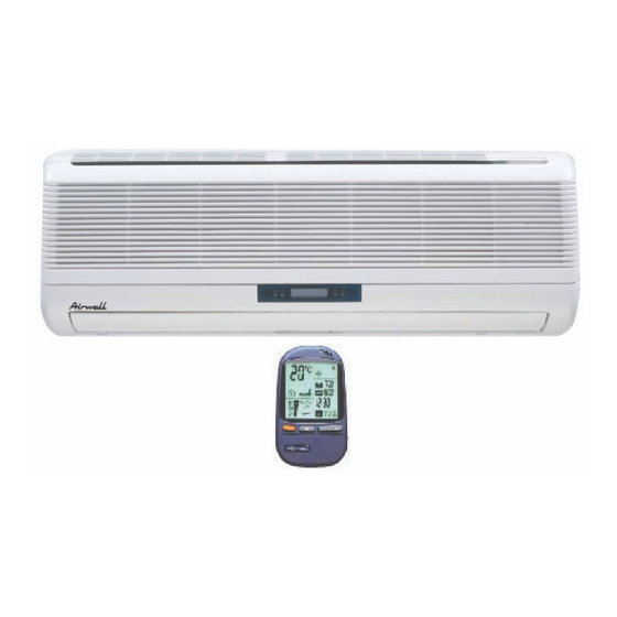
Technical Manual
REFRIGERANT
TM FLO-N A 0 GB
FLO N LCD Series
Indoor Units
FLO 7 N
FLO 9 N
FLO 12 N
FLO 14 N
FLO18 N
FLO 24 N
WNG 25
FLO 30 N
R410A
Outdoor Units
GC 7 N
ONG 7
GC 9 N
ONG 9
GC 12 N
ONG 12
GC 14 N
ONG 14
GC 18 N
—
GC 24 N
OU7-24
GC 24
—
GC 30 N
OU8 30/33
HEAT PUMP
08- 2005
Table of
Contents
Previous
Page
Next
Page
1
2
3
4
5
Advertisement
Table of Contents
Need help?
Do you have a question about the FLO 7 N and is the answer not in the manual?
Ask a question
Questions and answers
Related Manuals for Airwell FLO 7 N
Air Conditioner Airwell FLO 18 DCI Service Manual
Flo dc inverter series (105 pages)
Heat Pump Airwell SX 9 DCI Service Manual
Sx dci series (88 pages)
Heat Pump Airwell KXL DCI Series Service Manual
(55 pages)
Air Conditioner Airwell FLO 9 DCI Service Manual
Multi split trio quattro dci (94 pages)
Air Conditioner Airwell FLO 9 DCI Service Manual
Flo 9/12 dci series indoor/outdoor units (56 pages)
Air Conditioner Airwell Flo 9 INV Instruction Manual
Range inverter (30 pages)
Air Conditioner Airwell FLO 24 series Programming And Operating Manual
Dc inverter air conditioner split wall mounted (14 pages)
Air Conditioner Airwell DUO OU7-0909 Technical Manual
Duo n series, 9+9, 9+12 (44 pages)
Air Conditioner Airwell FLO 12 Technical Manual
Duo n series, 9+9, 9+12 (44 pages)
Air Conditioner Airwell Flow Logic II Series Operation & Installation Manual
Indoor unit (37 pages)
Air Conditioner Airwell HAF Series Operating Manual
Wall mounted range, r410a (10 pages)
Air Conditioner Airwell GCD 036 DCR Service Manual
Fbd floor ceiling dci series (133 pages)
Air Conditioner Airwell GCD 036 DCR Service Manual
Dc inverter (211 pages)
Air Conditioner Airwell FVVA-025N-01M22 User & Installation Manual
Ceiling floor type indoor unit fvva r410a (138 pages)
Air Conditioner Airwell FDMX-050N-09M25 User & Installation Manual
Ceiling & floor type air conditioner (39 pages)
Air Conditioner Airwell FFMD-100N-01T25 User & Installation Manual
Ceiling & floor type air conditioner (77 pages)
This manual is also suitable for:
Gc 7 n
Ong 7
Gc 9 n
Ong 9
Flo 12 n
Gc 12 n
...
Show all
Flo 14 n
Ong 12
Gc 14 n
Ong 14
Flo 9 n
Gc 18 n
Flo18 n
Flo 24 n
Wng 25
Gc 24 n
Ou7-24
Gc 24
Flo 30 n
Ou8 30/33
Gc 30 n
Table of Contents
Print
Rename the bookmark
Delete bookmark?
Delete from my manuals?
Login
Sign In
OR
Sign in with Facebook
Sign in with Google
Upload manual
Upload from disk
Upload from URL


Need help?
Do you have a question about the FLO 7 N and is the answer not in the manual?
Questions and answers