Advertisement
Quick Links
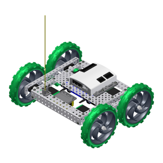
Build Phase
Overview
This phase describes the steps for building a VEX Tumbler robot.
The Vex Tumbler Robot
Phase Objectives
After completing this phase, you will be able to:
Identify and use the different parts of the VEX Classroom Kit.
Identify and use VEX parts to complete subassemblies in the creation of the Tumbler robot.
Assemble and drive a VEX Tumbler robot.
Prerequisites and Resources
Related phase resources are:
Introduction to VEX and Robotics.
75
Build Phase
Advertisement

Related Manuals for Vex Robotics Tumbler


Summary of Contents for Vex Robotics Tumbler
- Page 1 After completing this phase, you will be able to: Identify and use the different parts of the VEX Classroom Kit. Identify and use VEX parts to complete subassemblies in the creation of the Tumbler robot. Assemble and drive a VEX Tumbler robot.
- Page 2 Quantity Part Number Abbreviations ANTENNA HOLDER ANTENNA TUBE 7.2 VOLT RECHARGEABLE BATTERY BATTERY-STRAP BEAM-1000 BEARING-FLAT BEARING-RIVET CHASSIS BUMPER, 15 HOLE CHASSIS RAIL, 15 HOLE JUMPER ROUGH TERRAIN WHEEL MICROCONTROLLER NUT-832-KEPS Autodesk's VEX Robotics Unit 1: Introduction to VEX and Robotics...
- Page 3 Quantity Part Number Abbreviations PLATE, 5x15 HOLE RECEIVER RX75 SCREW-632-0250 SCREW-832-0250 SCREW-832-0375 SHAFT-3000 SHAFT COLLAR SPACER-THIN VEX MOTOR with CLUTCH Build Phase...
- Page 4 Activity Tumbler Right Side Drive In this activity, you build a complete robot called Tumbler. You start by building the right-side drive train. The completed model is as shown: To complete the first step: Locate one Chassis Rail [R15]. Fasten two Bearing Flats [BF] to the Chassis Rail using two Bearing Rivets [BR] for each Bearing Flat.
- Page 5 Build Phase...
- Page 6 Locate an additional Chassis Rail [R15] from the kit. Fasten two motors [MOT] to the Chassis Rail using two #6-32 x 1/4" screws [SS2] per motor. Make sure the motors are oriented correctly. Autodesk's VEX Robotics Unit 1: Introduction to VEX and Robotics...
- Page 7 To complete the next step: Orient the two assemblies and connect them by inserting #8-32 x 1/4" Screws [S2] into the end of the Beams. Insert a 3" Shaft [SQ3] into each motor, adding a Collar [COL] to the shaft as you insert it through the two rails.
- Page 8 To complete the next step: Slide a Thin Spacer [SP1] onto each shaft. Slide a Rough Terrain Wheel [W5] onto each shaft. Slide Shaft Collars [COL] up against the wheels and tighten. Autodesk's VEX Robotics Unit 1: Introduction to VEX and Robotics...
- Page 9 The right-side drive train is complete! Build Phase...
- Page 10 Fasten two Bearing Flats [BF] to the Chassis Rail using two Bearing Rivets [BR] for each Bearing Flat. Fasten two 1" Beams [B1] to the Chassis Rail using using #8-32 x 1/4" screws [S2]. The completed model is as shown: Autodesk's VEX Robotics Unit 1: Introduction to VEX and Robotics...
- Page 11 To complete the next step: Locate an additional Chassis Rail [R15] from the kit. Fasten two motors [MOT] to the Chassis Rail using two #6-32 x 1/4" screws [SS2] per motor. Make sure the motors are oriented correctly. The completed model is as shown: Build Phase...
- Page 12 When you have seated the shaft into the motor, slide the collar against the Bearing Flat and tighten. The collar prevents the shaft from coming out of the motor. Autodesk's VEX Robotics Unit 1: Introduction to VEX and Robotics...
- Page 13 To complete the next step: Slide a Thin Spacer [SP1] onto each shaft. Slide a Rough Terrain Wheel [W5] onto each shaft. Slide Shaft Collars [COL] up against the wheels and tighten. Build Phase...
- Page 14 The left side drive train is complete! Autodesk's VEX Robotics Unit 1: Introduction to VEX and Robotics...
- Page 15 Assemble the Base You now assemble the base, and then add the receiver, controller, battery, and antenna. To complete the first step: Bolt a Chassis Bumper [A15] to one end of the right side drive assembly using three #8-32 x 1/4"...
- Page 16 Attach the left side drive assembly using the same procedure as the previous step. The completed model is as shown: Autodesk's VEX Robotics Unit 1: Introduction to VEX and Robotics...
- Page 17 Attach a Plate 5x15 [P15] to the top of the chassis using #8-32 x 1/4" screws [S2] and Keps Nuts [NK]. The completed model is as shown: Build Phase...
- Page 18 Attach the Receiver Module [RX75] to the underside of the chassis using two #8-32 x 3/8" screws [S3] and Keps Nuts [NK]. Autodesk's VEX Robotics Unit 1: Introduction to VEX and Robotics...
- Page 19 The completed model is as shown: Build Phase...
- Page 20 Attach the Microcontroller [VMC] to the top of the chassis using two #8-32 x 3/8" screws [S3] and Keps Nuts [NK]. Autodesk's VEX Robotics Unit 1: Introduction to VEX and Robotics...
- Page 21 The completed model is as shown: Build Phase...
- Page 22 Attach two Battery Straps [BST] to the underside of the chassis using two #8-32 x 3/8" screws [S3] and Keps Nuts [NK] per strap. Attach the 7.2 Volt Robot Battery [BP]. Autodesk's VEX Robotics Unit 1: Introduction to VEX and Robotics...
- Page 23 The completed model is as shown: Build Phase...
- Page 24 Attach the Antenna Holder [AH] to the top of the chassis using one #8-32 x 3/8" screw [S3] and Keps Nut [NK]. Slide the antenna wire into the Antenna Tube [AT]. Insert the Antenna Tube into the Antenna Holder. Autodesk's VEX Robotics Unit 1: Introduction to VEX and Robotics...
- Page 25 The completed model is as shown: Build Phase...
- Page 26 Connect motor 1 [MOT-1] to port 1. Connect motor 2 [MOT-2] to port 2. Connect motor 3 [MOT-3] to port 8. Connect motor 4 [MOT-4], the motor nearest the antenna, to port 7. Autodesk's VEX Robotics Unit 1: Introduction to VEX and Robotics...
- Page 27 Insert a jumper into ANALOG/DIGITAL port 14 on the Microcontroller. To complete the next step: Connect the Receiver Module to port Rx1 on the microcontroller. Connect the Battery to the power port. Build Phase...
- Page 28 Your Tumbler is ready to roll! Note: Electrical connections are not shown. Autodesk's VEX Robotics Unit 1: Introduction to VEX and Robotics...
-
Page 29: Configure The Transmitter
Configure the Transmitter You now configure the Transmitter to reverse the directional controls on channel 1. See the VEX Inventor's Guide for detailed information on configuring the transmitter. Turn on the Transmitter. Check the voltage. If the voltage is less than 8.9 volts, recharge the batteries in the transmitter. Press and hold the MODE and SELECT buttons simultaneously until the CONFIG menu is displayed. - Page 30 Press the DATA INPUT minus key once. The arrow should display next to REV (below CH on the display). Press and hold the MODE and SELECT buttons simultaneously until the voltage is displayed. Turn on the Microcontroller and go for a drive! Autodesk's VEX Robotics Unit 1: Introduction to VEX and Robotics...
- Page 31 Amaze Phase Overview In this phase, students test their first VEX robot, Tumbler. Phase Objectives After completing this phase, you will be able to: Test and demonstrate a VEX robot. Identify the basic components of a VEX robot. Prerequisites and Resources Before starting this phase, you must have: Completed all sections in the Unit 1: Introduction to VEX and Robotics up to the Amaze phase.
- Page 32 Evaluation Tumbler Challenge In this challenge, you set up a basic obstacle course to test drive the Tumbler. You learn to drive a VEX robot, while discovering some of the neat features that Tumbler showcases. Challenge Instructions Choose any two “obstacles” available to you in your classroom. These obstacles act as pylons for the robot to navigate around.
- Page 33 Engineering Notebook In your engineering notebook, record a journal entry describing your experiences with the Tumbler robot. Now that you have gotten a taste of the VEX Robotics Design System, brainstorm a list of robots you would like to create.
Need help?
Do you have a question about the Tumbler and is the answer not in the manual?
Questions and answers