Table of Contents
Advertisement
Quick Links
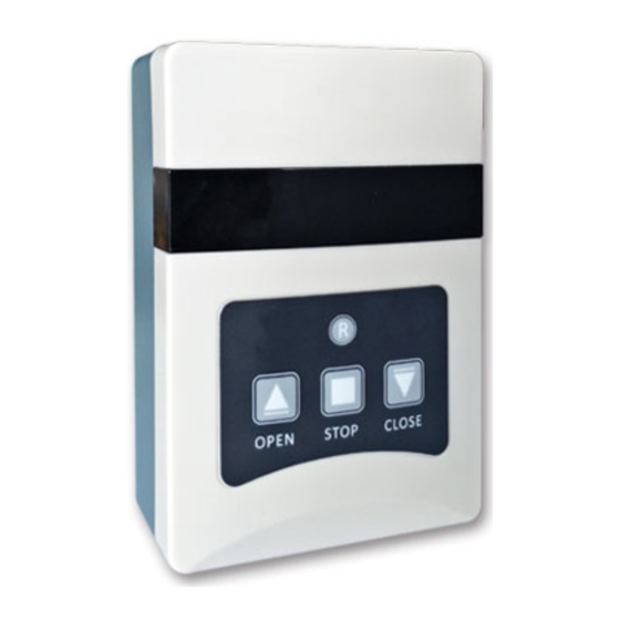
LK‐CP711‐30A EXTERNAL 30A POWER CONTROL PANEL
Feature
Consists of a motherboard and a membrane switch
Reset, Open/Stop/Close buttons and LED indicators
Single channel control
Can be cascaded with LK‐CP6/7/8 and LK‐FP3 control panel that achieves windows
of zone control and group control
Compatible with all Linkayl remote
Can handle external input signal of Manual Switch, Remote Control,
Smoke/Gas/Rain /Temperature & Humidity Sensors
Inching mode and continued‐run mode settable
With stroke memory function
External power supply up to DC24V/30A
Model List
Input Volt
Output Volt
Model
(V)
DC24
DC24 DC12
LK‐CP711‐30A
Application
External
Model
LK‐SCE‐D
Power
LK‐CP711‐30A 720W
25
Panel Description
LED / KEY
Color
L1 / K1
Blue
L2 / K2
Green
L3 / K3
Red
L4 / K4
Yellow
Freq
Temp (℃)
(V)
(MHz)
‐20 ~ +65
433.92
160L*110W*40H
LK‐L38A
LK‐LCD
LK‐TC
LK‐L
LK‐L‐S
600N/1KN
15
7
15
15
Status
Function
On / Off
AC power indicator, Reset
On / Off / Flash
Open
On / Off / Flash
Stop
On / Off / Flash
Close
Size (mm)
LK‐L38A
1500N
15
10
Advertisement
Table of Contents

Related Manuals for LinkAYL LK-CP711-30A


Summary of Contents for LinkAYL LK-CP711-30A
- Page 1 Feature Consists of a motherboard and a membrane switch Reset, Open/Stop/Close buttons and LED indicators Single channel control Can be cascaded with LK‐CP6/7/8 and LK‐FP3 control panel that achieves windows of zone control and group control Compatible with all Linkayl remote LED / KEY Color Status Function Can handle external input signal of Manual Switch, Remote Control, L1 / K1 Blue On / Off AC power indicator, Reset Smoke/Gas/Rain /Temperature & Humidity Sensors Inching mode and continued‐run mode settable ...
- Page 2 Terminals Control Mode Controler has inching mode and continued‐run mode which is default In the continued‐run mode, press the up / down key less than 1.5 seconds, the motor will run continuously, press the up / down key more than 1.5 seconds, the motor will stop after running a very short moment In the inching mode, press the up / down key less than 1.5 seconds, the motor will stop after running a very short moment, press the up / down key more than 1.5 seconds, the motor will run continuously Only the manual buttons on the panel, manual switch, remote control and cascade signal have inching mode Keep pressing both of UP and STOP button on the controler for 5 seconds, LEDs flash 3 times and turn off it’s inching mode for the controler, repeat the operation the controler turns to continued‐run mode Manual control After power on all the LEDs light for 1 second and turn off, the power indicator LED normally on Press reset button, all the LEDs light for 1 second and turn off, reset successfully Symbol ...
- Page 3 flashes 3 times and turns off T/H signal includes the signal from temperature or humidity sensor Press [UP] within 15 seconds Reset and Shielding LED flashes 3 times and turns off, code matched successfully After manual signal processed controler resets & receives input signal in real time After processing the signal from fire centre, smoke sensor or gas detector, the Clearing Single Code controler immediately shields all the input signals, the controler must be reset by Power controler on pressing K1 manually. Press STOP key on the controler for 5S, LED flashes 3 times and turns off After wired rain sensor signal processed, the controler shields lower priority ...
- Page 4 In the stroke memory setting state, the manual keys are forced to the more in the open condition The distance between controler and ground should be greater than 1.5 meters continued‐run mode, the remote control keys are forced to the inching mode Determine the stroke that needs to be memorized by pressing the manual key or The distance between controler and ceiling should be greater than 0.3 meters The distance between controler and motor should be greater than 1.5 meters the remote control key After the memorized strokes determined, press the up and down keys on the Avoid static interference and prevent static damage to electronic components ...
Need help?
Do you have a question about the LK-CP711-30A and is the answer not in the manual?
Questions and answers