
Related Manuals for InfiRay AT20


Summary of Contents for InfiRay AT20
- Page 1 AT20 Online Thermal Camera User Manual V1.0.5 IRay Technology Co., Ltd. www.iraytek.com...
-
Page 2: Table Of Contents
AT20 Online Thermal Camera User Manual Table of Contents 1. Legal Disclaimer ..............1 1.1 Legal Disclaimer .............. 1 1.2 Copyright ................. 2 1.3 Quality Assurance ............3 2. Safety Information ..............4 3. Notice to User ................. 6 3.1 Calibration ............... 6 3.2 Accuracy ................ - Page 3 AT20 Online Thermal Camera User Manual 9.1 Alarm Input ..............16 9.2 Alarm Output ..............16 10. Protocol Introduction ............17 10.1 Modbus TCP ..............17 10.2 MQTT ................17 11. Technical Data ..............24 12. Pin Configuration for Interfaces ........27 12.1 Ethernet Pin Configuration (8pin) .......
-
Page 4: Legal Disclaimer
AT20 Online Thermal Camera User Manual 1. Legal Disclaimer 1.1 Legal Disclaimer The thermal cameras manufactured by IRAY TECHNOLOGY are warranted for a period of two-year and the accessories are warranted for a period of three-month form the delivery date of the original purchase, provided such products have been under normal storage, use and maintenance. -
Page 5: Copyright
AT20 Online Thermal Camera User Manual 1.2 Copyright ©IRay Technology Co., Ltd. 2020. All right reserved worldwide. All contents in this manual, including words, pictures, images, etc., belong to IRAY TECHNOLOGY CO., LTD. (Hereinafter referred to as “THE COMPANY” or “IRAY TECHNOLOGY”). No part of the... -
Page 6: Quality Assurance
AT20 Online Thermal Camera User Manual 1.3 Quality Assurance The Quality Management System under which these products are developed and manufactured has been certified in accordance with the ISO 9001 standard. We reserve the right to make changes and improvements on any of... -
Page 7: Safety Information
AT20 Online Thermal Camera User Manual 2. Safety Information WARNING Before using the cleanser, make sure you read all applicable material safety data sheets (SDS) and warning labels on cleanser containers. WARNING Do not use too long screws when installing the front/rear mounting bracket, which may damage the thermal camera. - Page 8 AT20 Online Thermal Camera User Manual CAUTION Never apply cleaning solutions or similar liquids directly to the thermal camera, cables, or other components. CAUTION Be careful when you clean the infrared lenses. The lens has an anti-reflective coating which is easily damaged. Damage to the infrared lens can occur with...
-
Page 9: Notice To User
AT20 Online Thermal Camera User Manual 3. Notice to User 3.1 Calibration Annual calibration to the thermal camera is recommended to ensure the accuracy of temperature measurement, either through IRAY TECHNOLOGY or third-party organizations. 3.2 Accuracy For accurate measurement, it’s recommended that you use the thermal camera after it is stable for 30 minutes. -
Page 10: Camera Introduction
AT20 Online Thermal Camera User Manual 4. Camera Introduction Main Features: Accurate temperature measurement ⚫ Compact size ⚫ Support PoE ⚫ Bi-spectral display ⚫ Support multi-protocol access to industrial or IoT systems ⚫ Powerful web client ⚫ Wi-Fi hotspot configuration ⚫... -
Page 11: Product Figure And Explanation
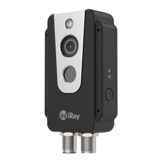
AT20 Online Thermal Camera User Manual 5. Product Figure and Explanation Table 5.1 Explanation of Product Appearance Explanation No. Explanation Fill light DC power supply and alarm input/output Digital camera Power LED light Infrared lens Network LED light Ethernet and PoE cable interface... -
Page 12: Quick Start Guide
1. After installing the thermal camera in the desired position, use the cable to connect the thermal camera and the computer normally. There are two power supply methods for AT20. Connect the device to the PoE port of the power supply through the M12 8-pin adapter cable or connect to the DC power supply through the M12 12-pin adapter cable. -
Page 13: Product And Accessories List
AT20 Online Thermal Camera User Manual 7. Product and Accessories List Table 7.1 Product and Accessories List Product and Accessories AT20 online thermal camera 44cm long M12 8-pin adapter cable Fixing accessories(screws, mounting stickers) Optional Accessories M12 12-pin adapter cable &alarm input/output cable... -
Page 14: Mechanical Installation
AT20 Online Thermal Camera User Manual 8. Mechanical Installation The front and back of the thermal camera are equipped with mounting interfaces, which can be installed with screws after the holes are punched with the auxiliary stickers in the package. In addition, we also provide two optional forms of front and back installation. -
Page 15: Installing Rear Shell
AT20 Online Thermal Camera User Manual Figure 8.1 Front Shell Installation 8.1.2 Installing Rear Shell As shown in Figure 8.2, please paste the sticker to the position to be installed, and then punch 4 Φ2.5 mounting holes according to the label on the sticker, and use 4 M2 screws to install the rear shell. -
Page 16: Front Mounting
AT20 Online Thermal Camera User Manual 8.2 Front Mounting There are four M4 threaded holes on the front mounting bracket for fixing. Step 1 Install the front mounting bracket As shown in Figure 8.3, connect the front mounting bracket and the thermal camera with ST2.2*8 self-tapping screws. -
Page 17: Rear Mounting
AT20 Online Thermal Camera User Manual Figure 8.5 8.3 Rear Mounting There are four M4 threaded holes on the rear mounting bracket for fixing. Step 1 Install the rear mounting bracket As shown in Figure 8.6, connect the rear mounting bracket and the thermal camera with ST2.2*8 self-tapping screws. - Page 18 AT20 Online Thermal Camera User Manual to the designated location. Figure 8.6 Figure 8.7 Figure 8.8...
-
Page 19: Alarm Input And Output
AT20 Online Thermal Camera User Manual 9. Alarm Input and Output 9.1 Alarm Input Support 1 active alarm input (photoelectric isolation), and the input voltage range is 3~5.5V. 9.2 Alarm Output Support 2 alarm outputs (switch value and photoelectric isolation),... -
Page 20: Protocol Introduction
Bit4:whether to trigger an alarm 0x000E+N*4 the highest temperature in the region 0x000F+N*4 the average temperature in the region 0x0010+N*4 the lowest temperature in the region *N:0~15 10.2 MQTT AT20 supports the MQTT protocol, as defined below: 1. The server sends the subject. AT20_IRAY... - Page 21 AT20 Online Thermal Camera User Manual 2. Set the configuration MQTT parameters through the Web interface, and enable the MQTT function. The configuration will be valid after saving and restarting. The camera will automatically connect to the MQTT server after restarting.
- Page 22 AT20 Online Thermal Camera User Manual Temperature data: "timestamp": "2021.4.9.15:52", # time stamp "ip": "192.168.1.21", #camera IP "type": 1, # data type : 0-image 1-temperature 2-temperature measurement "unit": "C", #Unit:℃ "data": ".." # temperature data base64 encode Temperature measurement data: temperature measurement function needs to be enabled in Web interface.
- Page 23 AT20 Online Thermal Camera User Manual "index": 1, "enable": "type": 0, "x0": "y0": "x1": "y1": "maxTemp": 0, "minTemp": 0, "avgTemp": 0 }, { "index": 2, "enable": "type": 0, "x0": "y0": "x1": "y1": "maxTemp": 0, "minTemp": 0, "avgTemp": 0 }, { "index": 3,...
- Page 24 AT20 Online Thermal Camera User Manual "index": 5, "enable": "type": 0, "x0": "y0": "x1": "y1": "maxTemp": 0, "minTemp": 0, "avgTemp": 0 }, { "index": 6, "enable": "type": 0, "x0": "y0": "x1": "y1": "maxTemp": 0, "minTemp": 0, "avgTemp": 0 }, { "index": 7,...
- Page 25 AT20 Online Thermal Camera User Manual "index": 9, "enable": "type": 0, "x0": "y0": "x1": "y1": "maxTemp": 0, "minTemp": 0, "avgTemp": 0 }, { "index": 10, "enable": "type": 0, "x0": "y0": "x1": "y1": "maxTemp": 0, "minTemp": 0, "avgTemp": 0 }, { "index": 11,...
- Page 26 AT20 Online Thermal Camera User Manual "index": 13, "enable": "type": 0, "x0": "y0": "x1": "y1": "maxTemp": 0, "minTemp": 0, "avgTemp": 0 }, { "index": 14, "enable": "type": 0, "x0": "y0": "x1": "y1": "maxTemp": 0, "minTemp": 0, "avgTemp": 0 }, { "index": 15,...
-
Page 27: Technical Data
AT20 Online Thermal Camera User Manual 11. Technical Data Table 11.1 AT20 Performance Parameters Imaging and Optical Data Resolution 256×192 NETD 40mK Frequency 30Hz Infrared Lens 3.2mm 56°×42° Focus Focus free Visible Light Pixels 2 million(SC2310) Visible 72°×61° Light Fill Light... - Page 28 AT20 Online Thermal Camera User Manual Ethernet Ethernet Functions control, imaging and power supply Ethernet Connector Type RJ45/ hotspot of thermal camera Ethernet Power Supply PoE is supported Network Protocol TCP,UDP,RTSP,HTTP,SMTP Interface Protocol ONVIF,GB28181,Modbus TCP,MQTT Image transmission Image Stream H.264/H.265 Format visible light1080P;...
- Page 29 AT20 Online Thermal Camera User Manual Shock 25G, IEC68-2-29 Vibration 2G, IEC68-2-6 Physical Data Dimension 109×55.9×29.5mm Weight 170g Housing Material Front shell is plastic and rear shell is aluminum alloy. . Others Certification CE/FCC/ROHS Cross-platform that supports secondary development of customers.
-
Page 30: Pin Configuration For Interfaces
AT20 Online Thermal Camera User Manual 12. Pin Configuration for Interfaces 12.1 Ethernet Pin Configuration (8pin) Configuration 12.2 Power Pin Configuration (12pin) Configuration Power + Power Ground ALARM_POWER1 ALARM_OUT1 ALARM_POWER2 ALARM_OUT2 ALARM_IN+ ALARM_IN- 11,12... -
Page 31: Mechanical Drawings
AT20 Online Thermal Camera User Manual 13. Mechanical Drawings... -
Page 32: Common Troubleshooting
AT20 Online Thermal Camera User Manual 14. Common Troubleshooting Troubles Possible Cause Solutions The supply voltage exceeds Check whether the power supply the normal working supply voltage is between 12 and 24V Camera cannot be voltage range. started. The power connector is Check whether the power cable is loose. -
Page 33: Cleaning Thermal Camera
AT20 Online Thermal Camera User Manual 15. Cleaning Thermal Camera 15.1 Cleaning Camera Housing, Cables and Other Items 15.1.1 Cleaning Liquids One of the following liquids can be used. ⚫warm water ⚫mild detergent solution 15.1.2 Cleaning Tools soft cloth 15.1.3 Cleaning Procedure Please follow this procedure: 1. -
Page 34: Cleaning Tools
AT20 Online Thermal Camera User Manual Commercial lens cleaning liquid with more than 30% isopropyl ⚫ alcohol. 96% ethyl alcohol (C ⚫ 15.2.2 Cleaning Tools Dustless cloth, absorbent cotton 15.2.3 Cleaning Procedure Please follow this procedure (Take dustless cloth as an example). -
Page 35: Appendix: Emissivity Of Common Materials
AT20 Online Thermal Camera User Manual Appendix: Emissivity of Common Materials Temperature(℃) Material Emissivity Water 0~100 0.95~0.98 Soil(dry) 0.92 Soil(wet) 0.95 Woods 0.962 Sand Sandstone 0.909~0.935 PVC plastic 0.93 Asphalt 0.967 Paint 0.92~0.94 Wallpaper 0.85~0.90 Cloth 0.98 Concrete 0.92 Pavement surface 0.974...
Need help?
Do you have a question about the AT20 and is the answer not in the manual?
Questions and answers