
Related Manuals for Eaton ZE/XTOM Series


Summary of Contents for Eaton ZE/XTOM Series
- Page 1 Handbuch/Manual 09/15 MN03407003Z-DE/EN Motorschutzrelais ZE/XTOM… Überlastüberwachung von Ex e-Motoren ZE/XTOM… motor-protective relay Overload monitoring of Ex e motors...
- Page 2 Alle Rechte, auch die der Übersetzung, vorbehalten. Kein Teil dieses Handbuches darf in irgendeiner Form (Druck, Fotokopie, Mikrofilm oder einem anderen Verfahren) ohne schriftliche Zustimmung der Firma Eaton Industries GmbH, Bonn, reproduziert oder unter Verwendung elektronischer Systeme verarbeitet, vervielfältigt oder verbreitet werden.
- Page 3 Gefahr! Danger! Gefährliche Dangerous elektrische electrical Spannung! voltage! Vor Beginn der Installationsarbeiten Before commencing the installation • Gerät spannungsfrei schalten • Disconnect the power supply of the device. • Gegen Wiedereinschalten sichern • Ensure relosing interlock that devices cannot be accidentally restarted. •...
- Page 4 09/15 MN03402003Z-DE/EN Überblick/Overview Motorschutzrelais ZE/XTOM… Überlastüberwachung von Ex e-Motoren ZE/XTOM… motor-protective relay Overload monitoring of Ex e motors Anhang/Appendix...
-
Page 5: Table Of Contents
09/15 MN03407003Z-DE/EN Inhalt Motorschutzrelais ZE/XTOM… Überlastüberwachung von Ex e- Motoren ZE/XTOM… motor-protective relay Overload monitoring of Ex e motors Anhang/Appendix Zu diesem Handbuch Zielgruppe Abkürzungen und Symbole Änderungsprotokoll Motorschutzrelais ZE/XTOM Vorwort Geräteübersicht Gerätebeschreibung – Überlastschutz mit Bimetallrelais – Strombereiche der ZE/XTOM-Relais –... - Page 6 09/15 MN03407003Z-DE/EN Geräte betreiben Einstellungen – Rücksetzung – Test Anhang/Appendix Typenschilder/ Rating plates ZE/XTOM Auslösekennlinien/Tripping characteristics ZE/XTOM – ZE-0,16/XTOMP16AC1 – ZE-0,24/XTOMP24AC1 – ZE-0,4/XTOMP40AC1 – ZE-0,6/XTOMP60AC1 – ZE-1,0/XTOM001AC1 – ZE-1,6/XTOM1P6AC1 – ZE-2,4/XTOM2P4AC1 – ZE-4/XTOM004AC1 – ZE-6/XTOM006AC1 – ZE-9/XTOM009AC1 – ZE-12/XTOM012AC1 EG-Konformitätserklärung/Declaration of CE Conformity (Doc No.: K 020710)
-
Page 7: Überlastüberwachung Von Ex E- Motoren
09/15 MN03407003Z-DE/EN Zu diesem Handbuch Das vorliegende Handbuch gilt für die Motorschutzrelais ZE/XTOM. Dieses Handbuch beschreibt die Überlastüberwachung zum Schutz von Ex e-Motoren in explosiongefährdeten Bereichen. Zielgruppe Das Handbuch richtet sich an Fachpersonal, das die Motor- schutzrelais installiert, in Betrieb nimmt und wartet. Abkürzungen und Symbole In diesem Handbuch werden Abkürzungen und Symbole eingesetzt, die folgende Bedeutung haben: Ex e... -
Page 8: Änderungsprotokoll
Änderungen ergeben: Redaktions- Seite Stichwort geän- ent- datum dert fällt 09/15 Sicherheitstechnische Betrachtung Zulassungen 01/11 allg. Aufnahme der Eaton-Typen allg. EEx e (jetzt: Ex e) EG-Baumusterprüfbescheinigungs- Nummer Typenschilder/Rating Plates EG-Konformitätserklärung/ Declaration of CE Conformity 02/02 – Erstausgabe – – –... -
Page 9: Motorschutzrelais Ze/Xtom
09/15 MN03407003Z-DE/EN Motorschutzrelais ZE/XTOM Vorwort Für den Schutz von Motoren in explosionsgefährdeten Bereichen gelten zusätzlich zu den Vorschriften nach EN 60079-14 und VDE 0165 Teil 1 separate Vorschriften für die entsprechenden Zündschutzarten. Für Motoren in der Zündschutzart „e“ „Erhöhte Sicherheit“ verlangt die Vorschrift EN 60079-7 zusätzliche Maßnahmen. -
Page 10: Geräteübersicht
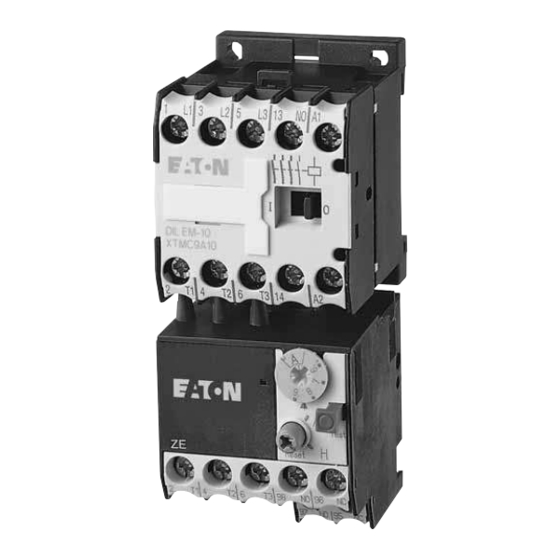
09/15 MN03407003Z-DE/EN Motorschutzrelais ZE/XTOM Geräteübersicht ① ② ③ Abbildung 1: Motorschutzrelais ZE/XTOM a Einstellrad Motorstrom b Taste AUS, Test c Wahlknopf Reset, Wiedereinschaltsperre Gerätebeschreibung Überlastschutz mit Bimetallrelais Die Motorschutzrelais ZE/XTOM sind dreipolige elektro- mechanische Motorschutzrelais mit Bimetallen. Sie sind zur Überwachung von Gleich- und Wechselstrom geeignet. -
Page 11: Strombereiche Der Ze/Xtom-Relais
09/15 MN03407003Z-DE/EN Gerätebeschreibung L1 L2 L3 (Q11/1) -S11 -Q11 -Q11 U V W Abbildung 2: Schaltbild eines Motorabganges mit Motorschutzrelais ZE/XTOM Sicherung Motorschutzrelais Motorschütz Motor Strombereiche der ZE/XTOM-Relais Die Motorschutzrelais werden mit Hilfe der Strom-Einstell- scheibe (a Abb. 1 auf Seite 6) auf den Motornennstrom eingestellt. -
Page 12: Temperaturkompensation
09/15 MN03407003Z-DE/EN Motorschutzrelais ZE/XTOM Tabelle 1: Strombereich der Motorschutzrelais ZE/XTOM Strombereich I ZE-0,16 XTOMP16AC1 0,10 - 0,16 ZE-0,24 XTOMP24AC1 0,16 - 0,24 ZE-0,4 XTOMP40AC1 0,24 - 0,4 ZE-0,6 XTOMP60AC1 0,4 - 0,6 ZE-1,0 XTOM001AC1 0,6 - 1,0 ZE-1,6 XTOM1P6AC1 1,0 - 1,6 ZE-2,4 XTOM2P4AC1 1,6 - 2,4... - Page 13 09/15 MN03407003Z-DE/EN Gerätebeschreibung Wird bei einem Phasenausfall ein Bimetall weniger ausge- lenkt, bleibt die Differenzialbrücke zurück und der Weg wird in zusätzlichen Auslöseweg umgewandelt, so dass es zu einer vorzeitigen Auslösung kommt. 97 95 97 95 98 96 98 96 98 96 Normalbetrieb ungestört dreiphasige Überlast...
-
Page 14: Wiedereinschaltung
09/15 MN03407003Z-DE/EN Motorschutzrelais ZE/XTOM Wiedereinschaltung Nach einer Auslösung müssen zunächst die Bimetalle abkühlen, bevor das Motorschutzrelais wieder zurückgesetzt werden kann. Mittels eines Wahlschalters kann zwischen manuellem und automatischem Zurücksetzen gewählt werden (a Abschnitt „Rücksetzung“ auf Seite 21). In der Stellung „Automatik“ fallen die Kontakte nach dem Abkühlen der Bimetalle automatisch zurück;... -
Page 15: Sicherheitstechnische Betrachtung
09/15 MN03407003Z-DE/EN Gerätebeschreibung Sicherheitstechnische Betrachtung Folgende Kenndaten für die funktionale Sicherheit wurden für das Motorschutzrelais ZE/XTOM ermittelt: Für die Betriebsart mit niedriger Anforderungsrate und der Architektur 1oo1, bestehend aus Subsystemen nach Typ A und Hardware-Fehler-Toleranz (HFT) 0 (siehe EN 61508 Teil 1 Tabelle 3 und EN 61508 Teil 2 Tabelle 2) für die Motorschutzrelais bei einer Umgebungstemperatur von 50 °C:... - Page 16 09/15 MN03407003Z-DE/EN Mittlere Wahrscheinlichkeit eines gefahrbringenden Ausfalls bei Anforderung der Sicherheitsfunktion bei einem Intervall für die Wiederholungsprüfung von 36 Monaten: 1. Anforderungsrate F 1/Jahr (low demand mode): : 2,6 x 10 Die mittlere Betriebsdauer zwischen zwei Ausfällen (MTBF) beträgt: 61 Jahre. Für die sicherheitsbezogenen Teile von Steuerungen nach EN ISO 13849 wurden bei einer Umgebungstemperatur von 50 °C folgende Daten ermittelt:...
-
Page 17: Projektierung
09/15 MN03407003Z-DE/EN Projektierung Überlastüberwachung von Durch besondere konstruktive Maßnahmen erreicht man bei Motoren im Ex e-Bereich Motoren die Zündschutzart Ex e. Die Motoren werden auf Basis der höchst zulässigen Oberflächentemperaturen Temperaturklassen zugeordnet. Zusätzlich werden die Erwärmungszeit t sowie das Verhältnis I von Anlauf- strom I zu Nennstrom I... - Page 18 09/15 MN03407003Z-DE/EN Projektierung Beispiel: I = 6, t = 10 s 7 8 9 10 Abbildung 5: Auslösekennlinie des Motorschutzrelais Der Motor wird zuverlässig geschützt.
-
Page 19: Kurzschluss-Schutz Der Motorschutzrelais
09/15 MN03407003Z-DE/EN Kurzschlussschutz der Motor- schutzrelais Kurzschlussschutz der Der Kurzschlussschutz der Motorschutzrelais ZE/XTOM kann Motorschutzrelais zum Teil sicherungslos oder sicherungsbehaftet erreicht werden. Die Zuordnungsart bezieht sich auf das eingesetzte Schütz DILEEM bzw. DILEM/XTMC (a nachfolgende Tabelle 2). Vorsicht! Zum Schutz von Ex e-Motoren ist nach EN 60947-4-1 nur die Zuordnungsart „2“... -
Page 20: Zulassungen
09/15 MN03407003Z-DE/EN Zulassungen Die Motorschutzrelais ZE/XTOM sind nach der Vorschrift IEC EN 60947 „Niederspannungsschaltgeräte“ gebaut und erfüllen die Forderungen nach der Richtlinie 94/9/EG (ATEX 100a) zum Schutz von Ex e-Motoren. Die Motorabgangsverdrahtung ist nach IEC/EN 60947-1 auszuführen. PTB 10 ATEX 3014 II(2)G [Ex d] [Ex e] [Ex px] II(2)D [Ex p] [Ex t] 0102... -
Page 21: Installation
09/15 MN03407003Z-DE/EN Installation Hinweise zur Installation Bei der mechanischen und elektrischen Installation ist die Montageanweisung IL03407007Z (frühere Bezeichnung AWA23-883) auf der Innenseite der Kartonverpackung zu beachten. Gefahr! Für den Explosionsschutz ist nur ein manuelles Zurück- setzen/Einschalten nach Abkühlung der Bimetalle des ZE/XTOM oder ein automatisches Zuschalten über eine Steuerungsverriegelung zum Motor bzw. - Page 22 09/15 MN03407003Z-DE/EN Installation L1 L2 L3 (Q11/1) -S11 -Q11 -Q11 U V W Abbildung 6: Schaltung verhindert automatischen Wiederanlauf F1 Sicherung F2 Motorschutzrelais Q11 Leistungsschütz M1 Motor Die Selbsthaltung des Leistungsschützes Q11 verhindert einen automatischen Wiederanlauf. Die Funktion „Fernreset“ bzw. „Remote“ kann erzielt werden, indem das Motorschutzrelais auf AUTO gestellt wird.
-
Page 23: Geräte Montieren
09/15 MN03407003Z-DE/EN Geräte montieren Geräte montieren Montieren Sie das Motorschutzrelais ZE/XTOM am Schütz DIL(E)EM/XTMC. 1.2 Nm Abbildung 7: Montage DIL(E)EM/XTMC und ZE/XTOM Montieren Sie beide in beliebiger Einbaulage, außer wie in Abb. 8 dargestellt. Abbildung 8: Nicht zugelassene Einbaulagen für DIL(E)EM/XTMC und ZE/XTOM (A1, A2 Spulenanschluss) - Page 24 09/15 MN03407003Z-DE/EN Verdrahten Sie die Motorleitungen. 1∼/ Abbildung 9: Hauptstromverdrahtung Folgende maximale Leitungsquerschnitte sind möglich. Tabelle 3: Maximale Leitungsquerschnitte der Motorzuleitungen ZE-... T1, T2, T3 T1, T2, T3 XTOM… 95-96, 97-98 95-96, 97-98 min. max. min. max. 0,75 – – 0,75 –...
-
Page 25: Geräte Betreiben
09/15 MN03407003Z-DE/EN Geräte betreiben Einstellungen Vor der Erstinbetriebnahme des Motorschutzrelais muss der Motornennstrom mit Hilfe einer Stromeinstellscheibe am Relais eingestellt werden (a Tabelle 1 auf Seite 8). Warnung! Bei einem kühlen Aufstellungsort des Motorschutzrelais (z. B. -5 °C) und einem warmen Aufstellungsort des Motors (z. -
Page 26: Test
09/15 MN03407003Z-DE/EN Test Das Motorschutzrelais ist mit einer Taste „Test“ versehen, in der eine Doppelfunktion integriert ist. TEST NO 97 NC 95 NO 98 NC 96 Abbildung 11: Schaltmöglichkeiten der Taste „Test“ Ein Ziehen der Taste hat das Öffnen der Hilfskontaktes 95-96 zur Folge und kann zum Abschalten des Schützes genutzt werden. - Page 27 09/15 MN03407003Z-DE/EN Contents Motorschutzrelais ZE/XTOM… Überlastüberwachung von Ex e- Motoren ZE/XTOM… motor-protective relay Overload monitoring of Ex e motors Anhang/Appendix About This Manual Target group Abbreviations and symbols List of revisions ZE/XTOM overload relays Foreword Device overview Description of device –...
-
Page 28: Ze/Xtom
09/15 MN03407003Z-DE/EN Using the device Settings – Reset – Test Anhang/Appendix Typenschilder/ Rating plates ZE/XTOM Auslösekennlinien/Tripping characteristics ZE/XTOM – ZE-0,16/XTOMP16AC1 – ZE-0,24/XTOMP24AC1 – ZE-0,4/XTOMP40AC1 – ZE-0,6/XTOMP60AC1 – ZE-1,0/XTOM001AC1 – ZE-1,6/XTOM1P6AC1 – ZE-2,4/XTOM2P4AC1 – ZE-4/XTOM004AC1 – ZE-6/XTOM006AC1 – ZE-9/XTOM009AC1 – ZE-12/XTOM012AC1 EG-Konformitätserklärung/Declaration of CE Conformity (Doc No.: K 020710) -
Page 29: Monitoring Of Ex E Motors
09/15 MN03407003Z-DE/EN About This Manual This manual covers the ZE/XTOM overload relays. It describes the overload monitoring system for the protec- tion of motors operating in potentially explosive atmo- spheres Ex e areas. Target group This manual addresses qualified personnel who install, commission and service the motor overload relays. -
Page 30: List Of Revisions
Page Keyword Modi- Omit- date fied 09/15 Safety analysis Approvals 01/11 General Inclusion of Eaton models General EEx e (now: Ex e) EC prototype test certification numbers Typenschilder/Rating Plates EG-Konformitätserklärung/ Declaration of CE Conformity 02/02 – Initial issue – –... -
Page 31: Ze/Xtom Overload Relays
09/15 MN03407003Z-DE/EN ZE/XTOM overload relays Foreword In addition to the degree of protection specified in the standards EN 60079-14 and VDE 0165 Part 1, further provisions have been made to ensure safety from ignition for motors operated in potentially explosive atmospheres. EN 60079-7 prescribes additional measures to be taken for the operation motors with “increased safety”... -
Page 32: Device Overview
09/15 MN03407003Z-DE/EN ZE/XTOM overload relays Device overview ① ② ③ Figure 1: ZE/XTOM overload relay a Setting dial for motor current b OFF button, test c Reset knob, reset lock-out Description of device Overload protection relays with bimetallic release The ZE/XTOM overload relays are 3 pole electromechanical overload relays using bimetallic elements. -
Page 33: Current Ranges For Ze/Xtom Relays
09/15 MN03407003Z-DE/EN Description of device L1 L2 L3 (Q11/1) -S11 -Q11 -Q11 U V W Figure 2: Circuit diagram of a motor connection with a ZE/XTOM overload relay Fuse Overload relay Motor contactor Motor Current ranges for ZE/XTOM relays The overload relays are set to the rated current of the motor by means of a current setting dial (a Fig. -
Page 34: Temperature Compensation
09/15 MN03407003Z-DE/EN ZE/XTOM overload relays Table 1: Current range of ZE/XTOM motor overload relays Type Current range I ZE-0.16 XTOMP16AC1 0.10 - 0.16 ZE-0.24 XTOMP24AC1 0.16 - 0.24 ZE-0.4 XTOMP40AC1 0.24 - 0.4 ZE-0.6 XTOMP60AC1 0.4 - 0.6 ZE-1.0 XTOM001AC1 0.6 - 1.0 ZE-1.6 XTOM1P6AC1... - Page 35 09/15 MN03407003Z-DE/EN Description of device If the path of action of one of the bimetallic releases is reduced due to a phase loss, the differential bridge is retarded and the distance is converted into an additional tripping distance, which leads to an early tripping. 97 95 97 95 98 96...
-
Page 36: Re-Closing
09/15 MN03407003Z-DE/EN ZE/XTOM overload relays Re-closing After tripping, the bimetallic releases must first cool down before the overload relay can be reset. Manual and auto- matic reset can be selected by means of a selector switch (a section "Reset" on Page 43). In auto mode, the contacts automatically fall back after the bimetallic releases have cooled down, whereas in manual mode the tripping must be acknowledged locally on the... -
Page 37: Safety Analysis
09/15 MN03407003Z-DE/EN Description of device Safety analysis The following functional safety characteristics were deter- mined for the motor overload relay ZE/XTOM: For low demand operating mode with a 1oo1 architecture, consisting of type A subsystems and a hardware fault toler- ance (HFT) of 0 (see Table 3 in EN 61508 Part 1 and Table 2 in EN 61508 Part 2) for the overload relays at an ambient temperature of 50 °C:... - Page 38 09/15 MN03407003Z-DE/EN Average probability of a dangerous failure when the safety function is on demand, using an interval of 36 months for repeat test: 1st demand level F 1/year (low demand mode): : 2.6 x 10 The mean lifespan between two failures (MTBF) is 61 years. For the safety-related parts of control systems as per EN ISO 13849, the following data was determined at an ambient temperature of 50 °C:...
-
Page 39: Projection
09/15 MN03407003Z-DE/EN Projection Overload monitoring of The Ex e protection of motors is achieved by means of motors in the Ex e area special design measures. The motors are assigned to temperature classes on the basis of the highest permissible surface temperatures. - Page 40 09/15 MN03407003Z-DE/EN Projection Example: I = 6, t = 10 s 7 8 9 10 Figure 5: Tripping characteristic of the overload relay The motor is reliably protected.
-
Page 41: Short-Circuit Protection Of The Overload Relay
09/15 MN03407003Z-DE/EN Short-circuit protection of the overload relay Short-circuit protection of The short-circuit protection of the ZE/XTOM overload relay the overload relay can be partially implemented either with or without a fuse. The type of coordination is related to the type of DILEEM or DILEM/XTMC contactor that is used (a following Table2). -
Page 42: Approvals
09/15 MN03407003Z-DE/EN Approvals The ZE/XTOM overload relays are compliant with IEC EN 60947 regulations for low-voltage switchgear and meet the requirements of the 94/9/EU (ATEX 100a) directives for the protection of Ex e motors. The wiring of the motor feeder must be carried out in accordance with IEC/EN 60947-1. -
Page 43: Installation
09/15 MN03407003Z-DE/EN Installation Installation instructions The mechanical and electrical instructional leaflet IL03407007Z (previous description AWA23-883) on the inside of the cardboard package must be observed. Danger! For explosion protection, it is only permissible to reset/switch on the motor protection relay manually, after the bimetallic release of ZE/XTOM has cooled down, or automatically via a control interlock circuit for the motor or electrical machinery. - Page 44 09/15 MN03407003Z-DE/EN Installation L1 L2 L3 (Q11/1) -S11 -Q11 -Q11 U V W Figure 6: Circuit prevents automatic restart F1 Fuse F2 Overload relay Q11 Contactor M1 Motor The latching function of the Q11 contactor relay prevents an automatic restart. The “remote reset”/“remote”...
-
Page 45: Fitting The Device
09/15 MN03407003Z-DE/EN Fitting the device Fitting the device Mount the ZE/XTOM overload relay on the DIL(E)EM/XTMC contactor. 1.2 Nm Figure 7: Mounting DIL(E)EM/XTMC and ZE/XTOM Both can be mounted in any position, apart from as shown in Fig. 8. Figure 8: Impermissible mounting positions for DIL(E)EM/XTMC and ZE/XTOM (A1, A2 coil connection) - Page 46 09/15 MN03407003Z-DE/EN Wire the motor cables. 1∼/ Figure 9: Main circuit wiring The following maximum cable cross sections are possible. Table 3: Maximum conductor cross-sections of the motor cables ZE-... T1, T2, T3 T1, T2, T3 XTOM… 95-96, 97-98 95-96, 97-98 Min.
-
Page 47: Using The Device
09/15 MN03407003Z-DE/EN Using the device Settings Prior to initial commissioning, the rated motor current must be set on the overload relay by means of the current dial (a Table 1 on Page 30). Warning! If the overload relay is installed at a cool location (e.g. -
Page 48: Test
09/15 MN03407003Z-DE/EN Test The overload relay is provided with a Test button that contains a double function. TEST NO 97 NC 95 NO 98 NC 96 Figure 11: Switching options of the Test button The auxiliary contact 95-96 is opened by pulling the Test button, and can thus be used to switch off the contactor relay. -
Page 49: Anhang/Appendix
09/15 MN03407003Z-DE/EN Anhang/Appendix Typenschilder/ Rating plates ZE/XTOM IEC/EN 60947-4-1 6000 V 690 V Class 10A max. Type "1" A gL/gG max. Type "2" A gL/gG IEC/EN 60947-5-1 Normal Test AC-15 U 220/240 380/415 500 95-96 97-98 0102 II(2)G [Ex d][Ex e][Ex px] II(2)D [Ex p][Ex t] GB 14048.4 PTB 10 ATEX 3010... - Page 50 09/15 MN03407003Z-DE/EN Anhang/Appendix Tabelle/Table 4: Werte der einzelnen Typen/Values for indivi- dual types ZE-0,16 XTOMP16AC1 ZE-0,24 XTOMP24AC1 ZE-0,4 XTOMP40AC1 ZE-0,6 XTOMP60AC1 ZE-1,0 XTOM001AC1 ZE-1,6 XTOM1P6AC1 ZE-2,4 XTOM2P4AC1 ZE-4 XTOM004AC1 ZE-6 XTOM006AC1 ZE-9 XTOM009AC1 ZE-12 XTOM012AC1...
-
Page 51: Ze/Xtom
09/15 MN03407003Z-DE/EN Auslösekennlinien/ Tripping characteristics ZE/XTOM Auslösekennlinien/ Tripping characteristics ZE/XTOM... -
Page 52: Ze-0,16/Xtomp16Ac1
09/15 MN03407003Z-DE/EN Anhang/Appendix ZE-0,16/XTOMP16AC1 Bereich/Range 0,10 - 0,16 A (NM - HM) Umgebungstemperatur/Ambient air temperature 20 °C Auslöseklasse/Tripping class 10 A Toleranzbereich/Tolerance range g 20 % Datum/Date 10.09.97 Einstellung/ Auslösezeit/Tripping time t [s] Setting 3-phase a 2-phase c 3-phase b 2-phase d 3 x I 7,2 x I... -
Page 53: Ze-0,24/Xtomp24Ac1
09/15 MN03407003Z-DE/EN Auslösekennlinien/ Tripping characteristics ZE/XTOM ZE-0,24/XTOMP24AC1 Bereich/Range 0,16 - 0,24 A (NM - HM) Umgebungstemperatur/Ambient air temperature 20 °C Auslöseklasse/Tripping class 10 A Toleranzbereich/Tolerance range g 20 % Datum/Date 02.10.97 Einstellung/ Auslösezeit/Tripping time t [s] Setting 3-phase a 2-phase c 3-phase b 2-phase d 3 x I... -
Page 54: Ze-0,4/Xtomp40Ac1
09/15 MN03407003Z-DE/EN Anhang/Appendix ZE-0,4/XTOMP40AC1 Bereich/Range 0,24 - 0,4 A (NM - HM) Umgebungstemperatur/Ambient air temperature 20 °C Auslöseklasse/Tripping class 10 A Toleranzbereich/Tolerance range g 20 % Datum/Date 06.10.97 Einstellung/ Auslösezeit/Tripping time t [s] Setting 3-phase a 2-phase c 3-phase b 2-phase d 3 x I 11,8... -
Page 55: Ze-0,6/Xtomp60Ac1
09/15 MN03407003Z-DE/EN Auslösekennlinien/ Tripping characteristics ZE/XTOM ZE-0,6/XTOMP60AC1 Bereich/Range 0,4 - 0,6 A (NM - HM) Umgebungstemperatur/Ambient air temperature 20 °C Auslöseklasse/Tripping class 10 A Toleranzbereich/Tolerance range g 20 % Datum/Date 06.10.97 Einstellung/ Auslösezeit/Tripping time t [s] Setting 3-phase a 2-phase c 3-phase b 2-phase d 3 x I... -
Page 56: Ze-1,0/Xtom001Ac1
09/15 MN03407003Z-DE/EN Anhang/Appendix ZE-1,0/XTOM001AC1 Bereich/Range 0,6 - 1,0 A (NM - HM) Umgebungstemperatur/Ambient air temperature 20 °C Auslöseklasse/Tripping class 10 A Toleranzbereich/Tolerance range g 20 % Datum/Date 06.10.97 Einstellung/ Auslösezeit/Tripping time t [s] Setting 3-phase a 2-phase c 3-phase b 2-phase d 3 x I 25,5... -
Page 57: Ze-1,6/Xtom1P6Ac1
09/15 MN03407003Z-DE/EN Auslösekennlinien/ Tripping characteristics ZE/XTOM ZE-1,6/XTOM1P6AC1 Bereich/Range 1,0 - 1,6 A (NM - HM) Umgebungstemperatur/Ambient air temperature 20 °C Auslöseklasse/Tripping class 10 A Toleranzbereich/Tolerance range g 20 % Datum/Date 06.10.97 Einstellung/ Auslösezeit/Tripping time t [s] Setting 3-phase a 2-phase c 3-phase b 2-phase d 3 x I... -
Page 58: Ze-2,4/Xtom2P4Ac1
09/15 MN03407003Z-DE/EN Anhang/Appendix ZE-2,4/XTOM2P4AC1 Bereich/Range 1,6 - 2,4 A (NM - HM) Umgebungstemperatur/Ambient air temperature 20 °C Auslöseklasse/Tripping class 10 A Toleranzbereich/Tolerance range g 20 % Datum/Date 06.10.97 Einstellung/ Auslösezeit/Tripping time t [s] Setting 3-phase a 2-phase c 3-phase b 2-phase d 3 x I 24,7... -
Page 59: Ze-4/Xtom004Ac1
09/15 MN03407003Z-DE/EN Auslösekennlinien/ Tripping characteristics ZE/XTOM ZE-4/XTOM004AC1 Bereich/Range 2,4 - 4 A (NM - HM) Umgebungstemperatur/Ambient air temperature 20 °C Auslöseklasse/Tripping class 10 A Toleranzbereich/Tolerance range g 20 % Datum/Date 29.06.01 Einstellung/ Auslösezeit/Tripping time t [s] Setting 3-phase a 2-phase c 3-phase b 2-phase d 3 x I... -
Page 60: Ze-6/Xtom006Ac1
09/15 MN03407003Z-DE/EN Anhang/Appendix ZE-6/XTOM006AC1 Bereich/Range 4 - 6 A (NM - HM) Umgebungstemperatur/Ambient air temperature 20 °C Auslöseklasse/Tripping class 10 A Toleranzbereich/Tolerance range g 20 % Datum/Date 06.10.97 Einstellung/ Auslösezeit/Tripping time t [s] Setting 3-phase a 2-phase c 3-phase b 2-phase d 3 x I 18,1... -
Page 61: Ze-9/Xtom009Ac1
09/15 MN03407003Z-DE/EN Auslösekennlinien/ Tripping characteristics ZE/XTOM ZE-9/XTOM009AC1 Bereich/Range 6 - 9 A (NM - HM) Umgebungstemperatur/Ambient air temperature 20 °C Auslöseklasse/Tripping class 10 A Toleranzbereich/Tolerance range g 20 % Datum/Date 08.10.97 Einstellung/ Auslösezeit/Tripping time t [s] Setting 3-phase a 2-phase c 3-phase b 2-phase d 3 x I... -
Page 62: Ze-12/Xtom012Ac1
09/15 MN03407003Z-DE/EN Anhang/Appendix ZE-12/XTOM012AC1 Bereich/Range 9 - 12 A (NM - HM) Umgebungstemperatur/Ambient air temperature 20 °C Auslöseklasse/Tripping class 10 A Toleranzbereich/Tolerance range g 20 % Datum/Date 05.01.98 Einstellung/ Auslösezeit/Tripping time t [s] Setting 3-phase a 2-phase c 3-phase b 2-phase d 3 x I 7,2 x I... -
Page 63: Eg-Konformitätserklärung/Declaration Of
(Doc No.: CE1400095) EG-Konformitätserklärung / Declaration of EC Conformity (Doc No.: CE1400095) EG-Konformitätserklärung Declaration of EC Conformity Wir / We, Eaton Industries GmbH Hein-Moeller-Str. 7-11, 53115 Bonn (Germany) erklären hiermit, dass das Produkt (die Produktfamilie) declare that the product (family) entsprechend der Auflistung auf Seite 2 und vorausgesetzt, dass es unter Berücksichtigung der relevanten Herstellerangaben, Einbauanweisungen und... - Page 64 09/15 MN03407003Z-DE/EN Anhang/Appendix EG-Konformitätserklärung / Declaration of EC Conformity (Doc No.: CE1400095) Typen des Sortiments Types within the range Die Konformitätserklärung gilt für folgende Typen der Produktfamilie und in Kombination mit den darunter folgenden Produkten: The declaration of conformity applies to the following types within the product family and in combination with products listed below: 28.09.2015 28.09.2015...
Need help?
Do you have a question about the ZE/XTOM Series and is the answer not in the manual?
Questions and answers