Table of Contents
Advertisement
Available languages
Available languages
Quick Links
Advertisement
Chapters
Table of Contents

Related Manuals for Eaton ZB12/XTOB BC1 Series


Summary of Contents for Eaton ZB12/XTOB BC1 Series
- Page 1 10/10 MN03407004Z-DE/EN Handbuch/Manual ersetzt/replaces 05/05 AWB2300-1527D/GB Motorschutzrelais/Motor-protective relays ZB12/XTOB…BC1 und/and ZB32/XTOB…CC1 Überlastüberwachung von Ex e-Motoren/ Overload monitoring of Ex e motors...
- Page 2 Alle Rechte, auch die der Übersetzung, vorbehalten. Kein Teil dieses Handbuches darf in irgendeiner Form (Druck, Fotokopie, Mikrofilm oder einem anderen Verfahren) ohne schriftliche Zustimmung der Firma Eaton Industries GmbH, Bonn, reproduziert oder unter Verwendung elektronischer Systeme verarbeitet, vervielfältigt oder verbreitet werden.
- Page 3 Gefahr! Danger! Gefährliche Dangerous elektrische electrical Spannung! voltage! Vor Beginn der Installationsarbeiten Before commencing the installation • Gerät spannungsfrei schalten • Disconnect the power supply of the device. • Gegen Wiedereinschalten sichern • Ensure relosing interlock that devices cannot be accidentally restarted. •...
- Page 4 10/10 MN03407004Z-DE/EN Überblick/Overview Motorschutzrelais ZB12/XTOB…BC1 und ZB32/XTOB…CC1 Überlastüberwachung von Ex e-Motoren Motor-protective relays ZB12/XTOB…BC1 and ZB32/XTOB…CC1 Overload monitoring of Ex e motors Anhang/Appendix...
-
Page 5: Table Of Contents
10/10 MN03407004Z-DE/EN Inhalt Zu diesem Handbuch Zielgruppe Abkürzungen und Symbole Änderungsprotokoll Motorschutzrelais ZB12/XTOB…BC1 und ZB32/XTOB…CC1 Vorwort Geräteübersicht Gerätebeschreibung – Überlastschutz mit Bimetallrelais – Strombereiche der Motorschutzrelais – Temperaturkompensation – Phasenausfall – Wiedereinschaltung – Testfunktion Projektierung Überlastüberwachung von Motoren im Ex e-Bereich Einstellung der Überstromschutzeinrichtung –... - Page 6 10/10 MN03407004Z-DE/EN Inhalt Anhang/Appendix Typenschilder/Rating plates – Motorschutzrelais/Overload relay ZB12/ XTOB…BC1 und/and ZB32/XTOB…CC1 Auslösekennlinien/ Tripping characteristics – ZB12-0,16/XTOBP16BC1 und/and ZB32-0,16/ XTOBP16CC1 – ZB12-0,24/XTOBP24BC1 und/and ZB32-0,24/ XTOBP24CC1 – ZB12-0,4/XTOBP40BC1 und/and ZB32-0,4/ XTOBP40CC1 – ZB12-0,6/XTOBP60BC1 und/and ZB32-0,6/ XTOBP60CC1 – ZB12-1/XTOB001BC1 und/and ZB32-1/ XTOB001CC1 –...
-
Page 7: Zu Diesem Handbuch
10/10 MN03407004Z-DE/EN Zu diesem Handbuch Das vorliegende Handbuch gilt für die Motorschutzrelais ZB12/XTOB…BC1 und ZB32/XTOB…CC1. Dieses Handbuch beschreibt die Überlastüberwachung zum Schutz von Ex e-Motoren in explosiongefährdeten Berei- chen. Zielgruppe Dieses Handbuch richtet sich an Fachpersonal, das die Motorschutzrelais installiert, in Betrieb nimmt und wartet. Abkürzungen und Symbole In diesem Handbuch werden Abkürzungen und Symbole eingesetzt, die folgende Bedeutung haben: Ex e... -
Page 8: Änderungsprotokoll
10/10 MN03407004Z-DE/EN Zu diesem Handbuch Gefahr! warnt vor schweren Sachschäden und schweren Verletzungen oder Tod. Für eine gute Übersichtlichkeit finden Sie auf den linken Seiten im Kopf die Kapitelüberschrift und auf den rechten Seiten den aktuellen Abschnitt, Ausnahmen sind Kapitel- anfangsseiten und leere Seiten am Kapitelende. -
Page 9: Motorschutzrelais Zb12/Xtob
10/10 MN03407004Z-DE/EN Motorschutzrelais ZB12/ XTOB…BC1 und ZB32/XTOB…CC1 Vorwort Für den Schutz von Motoren in explosionsgefährdeten Bereichen gelten zusätzlich zu den Vorschriften nach EN 60079-14 und VDE 0165 Teil 1 separate Vorschriften für die entsprechenden Zündschutzarten. Für Motoren in der Zündschutzart „e“ „Erhöhte Sicherheit“ verlangt die Vorschrift EN 60079-7 zusätzliche Maßnahmen. -
Page 10: Geräteübersicht
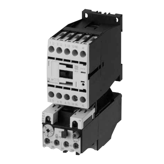
10/10 MN03407004Z-DE/EN Motorschutzrelais ZB12/ XTOB…BC1 und ZB32/ XTOB…CC1 Geräteübersicht Abbildung 1: Motorschutzrelais ZB12/XTOB…BC1 Abbildung 2: Motorschutzrelais ZB32/XTOB…CC1 Gerätebeschreibung Überlastschutz mit Bimetallrelais Die Motorschutzrelais ZB12/XTOB...BC1 und ZB32/ XTOB…CC1 sind dreipolige elektromechanische Motor- schutzrelais mit Bimetallen. Sie sind zur Überwachung von Gleich- und Wechselstrom geeignet. Die Motorschutzrelais ZB12/XTOB...BC1 und ZB32/ XTOB…CC1 sind als Direktanbau an die Schütze DILM…/ XTCE…... - Page 11 10/10 MN03407004Z-DE/EN Gerätebeschreibung Zusätzlich ist das Relais ZB32/XTOB…CC1 in Kombination mit einer Einzelaufstellung einzeln einsetzbar. Tabelle 2: Einzelaufstellung Motorschutzrelais Einzelaufstellung ZB32-… XTOB…CC1 ZB32-XEZ XTOBXDINC Bei einer Überlastauslösung schalten die Hilfsschalter 95-96 und 97-98 um und unterbrechen den Steuerstromkreis des zugehörigen Leistungsschützes. Sie schalten so indirekt den Stromfluss des zu überwachenden Motors ab.
-
Page 12: Strombereiche Der Motorschutzrelais
10/10 MN03407004Z-DE/EN Motorschutzrelais ZB12/ XTOB…BC1 und ZB32/ XTOB…CC1 Strombereiche der Motorschutzrelais Die Motorschutzrelais werden mit Hilfe einer Strom-Einstell- scheibe auf den Motornennstrom eingestellt. Mit verschiedenen Typen können Motoren von 0,1 bis 32 A Motornennstrom überwacht werden. Tabelle 3: Strombereiche ZB12/XTOB…BC1 Strombereich I [A] ZB12-0,16 XTOBP16BC1... -
Page 13: Temperaturkompensation
10/10 MN03407004Z-DE/EN Gerätebeschreibung Tabelle 4: Strombereiche ZB32/XTOB…CC1 Strombereich I [A] ZB32-0,16 XTOBP16CC1 0,1 - 0,16 ZB32-0,24 XTOBP24CC1 0,16 - 0,24 ZB32-0,4 XTOBP40CC1 0,24 - 0,4 ZB32-0,6 XTOBP60CC1 0,4 - 0,6 ZB32-1,0 XTOB001CC1 0,6 - 1,0 ZB32-1,6 XTOB1P6CC1 1,0 - 1,6 ZB32-2,4 XTOB2P4CC1 1,6 - 2,4... -
Page 14: Phasenausfall
10/10 MN03407004Z-DE/EN Motorschutzrelais ZB12/ XTOB…BC1 und ZB32/ XTOB…CC1 Phasenausfall Motorschutzrelais ZB12/XTOB…BC1 und ZB32/XTOB…CC1 sind phasenausfallempfindlich. Die Auslenkung aller drei Bimetalle wirkt auf eine Auslösebrücke, die bei Erreichen des Grenzwertes einen Sprungschalter umschaltet. Gleichzeitig verschieben alle drei Bimetalle die Differenzialbrücke. Wird bei einem Phasenausfall ein Bimetall weniger ausgelenkt, bleibt die Differentialbrücke zurück und der Weg wird in zusätzlichen Auslöseweg umgewandelt, so dass es zu einer... -
Page 15: Wiedereinschaltung
10/10 MN03407004Z-DE/EN Gerätebeschreibung Abbildung 5: Verdrahtung der Motorschutzrelais für den Schutz von Wechselstrom- oder Gleichstrommotoren (Reihenschaltung der Bimetallauslöser) (a Abschnitt „Auslösekennlinien“ ab Seite 55) Wiedereinschaltung Nach einer Auslösung müssen zunächst die Bimetalle abkühlen, bevor das Motorschutzrelais wieder zurückgesetzt werden kann. Mittels eines Wahlschalters kann zwischen manuellem und automatischer Rücksetzung gewählt werden (a Abschnitt „Rücksetzung“auf Seite 25). -
Page 16: Testfunktion
10/10 MN03407004Z-DE/EN Motorschutzrelais ZB12/ XTOB…BC1 und ZB32/ XTOB…CC1 Testfunktion Durch eine zusätzliche Testtaste kann die Funktionstüchtig- keit der Hilfsschalter kontrolliert werden. Hierbei hat die Testtaste eine Doppelfunktion: • Das Drücken der Testtaste öffnet den Öffner 95-96. Nach dem Loslassen fällt der Öffner wieder zurück. Diese Funktion kann zum manuellen Ausschalten des Motors genutzt werden. -
Page 17: Projektierung
10/10 MN03407004Z-DE/EN Projektierung Überlastüberwachung von Durch besondere konstruktive Maßnahmen erreicht man bei Motoren im Ex e-Bereich Motoren die Zündschutzart Ex e. Die Motoren werden auf Basis der höchst zulässigen Oberflächentemperaturen Temperaturklassen zugeordnet. Zusätzlich wird die Erwär- mungszeit t und das Verhältnis Anlaufstrom zu Nennstrom bestimmt und auf dem Motor angegeben. -
Page 18: Kurzschlussschutz Der Motorschutzrelais
10/10 MN03407004Z-DE/EN Projektierung Beispiel: I = 6, t = 10 s 7 8 9 10 Abbildung 6: Auslösekennlinie des Motorschutzrelais Der Motor wird zuverlässig geschützt. Kurzschlussschutz der Motorschutzrelais Der Kurzschlussschutz der Motorschutzrelais wird durch Sicherungen realisiert. Bei Direktanbau an ein Schütz wird die Vorsicherung des Schützes für die entsprechende Zuord- nungsart mit berücksichtigt. - Page 19 10/10 MN03407004Z-DE/EN Einstellung der Über- stromschutzeinrichtung Tabelle 5: ZB12/XTOB…BC1 in Direktanbau Motorschutzrelais Schütz Sicherung gG/gL [A] Bemessungs- Zuord- Zuord- kurzschluss- nungsart nungsart strom „1“ „2“ [kA] ZB12-0,16 XTOBP16BC1 DILM7 DILM9 ZB12-0,24 XTOBP24BC1 DILM12 ZB12-0,4 XTOBP40BC1 DILM15 XTCE007B ZB12-0,6 XTOBP60BC1 XTCE009B ZB12-1,0 XTOB001BC1 XTCE012B...
-
Page 20: Zb32/Xtob
10/10 MN03407004Z-DE/EN Projektierung Tabelle 6: ZB32/XTOB…CC1 in Direktanbau oder Einzelaufstellung Motorschutzrelais Schütz Sicherung gG/gL [A] Bemessungs- Zuord- Zuord- kurzschluss- nungsart nungsart strom „1“ „2“ [kA] ZB32-0,16 XTOBP16CC1 DILM17 DILM25 ZB32-0,24 XTOBP24CC1 DILM32 ZB32-0,4 XTOBP40CC1 XTCE018C XTCE025C ZB32-0,6 XTOBP60CC1 XTCE032C ZB32-1,0 XTOB001CC1 ZB32-1,6 XTOB1P6CC1... -
Page 21: Zulassungen
10/10 MN03407004Z-DE/EN Zulassungen Zulassungen Die Motorschutzrelais ZB12/XTOB…BC1 und ZB32/ XTOB…CC1 sind nach der Vorschrift IEC EN 60947 Nieder- spannungsschaltgeräte gebaut und erfüllen die Forderungen nach der Richtlinie 94/9/EG (ATEX 100a) zum Schutz von Ex e-Motoren. Außerdem können nach EN 50281-1-1 und EN 50281-1-2 Motoren in den Zonen 21 und 22 (Bereiche mit brennbarem Staub) geschützt werden. - Page 22 10/10 MN03407004Z-DE/EN...
-
Page 23: Installation
10/10 MN03407004Z-DE/EN Installation Hinweise zur Installation Bei der mechanischen und elektrischen Installation ist die entsprechende Montageanweisung zu beachten. Die Monta- geanweisung ist auf der Innenseite der Kartonverpackung aufgedruckt. ZB12/XTOB…BC1, ZB32/XTOB…CC1 Die Montageanweisung AWA2300-2114 ist ab der Ausgabe mit Redaktionsdatum 10/10 umbenannt in IL03407015Z. - Page 24 10/10 MN03407004Z-DE/EN Installation L1 L2 L3 (Q11/1) -S11 -Q11 -Q11 U V W Abbildung 7: Schaltung verhindert automatischen Wiederanlauf F1 Sicherung F2 Motorschutzrelais Q11 Leistungsschütz M1 Motor Die Selbsthaltung des Leistungsschützes Q11 verhindert einen automatischen Wiederanlauf.
-
Page 25: Geräte Montieren
10/10 MN03407004Z-DE/EN Geräte montieren Geräte montieren Die Motorschutzrelais ZB12/XTOB…BC1 und ZB32/ XTOB…CC1 können direkt am Schütz montiert werden. Das ZB32/XTOB…CC1 kann zusätzlich in Kombination mit der Einzelaufstellung einzeln eingesetzt werden. Tabelle 7: Direktanbau Motorschutzrelais Schütz ZB12-… XTOB…BC1 DILM7 XTCE007B DILM9 XTCE009B DILM12 XTCE012B... - Page 26 10/10 MN03407004Z-DE/EN Installation Montieren Sie die Geräte wie in den nachfolgenden Abbildungen angegeben. ZB12/XTOB…BC1 ZB32/XTOB…CC1 ZB32/XTOB…CC1 ZB32-XEZ/ XTOBXDINC Abbildung 8: Montage ZB12/XTOB…BC1, ZB32/XTOB…CC1 Die Einzelaufstellung ZB32-XEZ/XTOBXDINC kann auf einer Hutschiene oder direkt auf der Montageplatte montiert werden. Tabelle 9: Maße zur Montage ZB32-XEZ/XTOBXDINC Bohrmaße (B x H) [mm] 35 x 75...
- Page 27 10/10 MN03407004Z-DE/EN Geräte montieren Verdrahten Sie die Motorleitungen. 1h/H Abbildung 9: Hauptstromverdrahtung Folgende Leitungsquerschnitte sind möglich. Tabelle 10: Leitungsquerschnitte Hauptstrombahnen Hilfsstrombahnen ZB12-.../ ZB32-.../ 95-96 XTOB…BC1 XTOB…CC1 97-98 1 x (1 - 6) 1 x (1 - 6) 1 x (0,75 - 4) 2 x (1 - 6) 2 x (1 - 6) 2 x (0,75 - 4)
- Page 28 10/10 MN03407004Z-DE/EN...
-
Page 29: Geräte Betreiben
10/10 MN03407004Z-DE/EN Geräte betreiben Einstellungen Vor der Erstinbetriebnahme des Motorschutzrelais muss der Motornennstrom mit Hilfe einer Stromeinstellscheibe am Relais eingestellt werden (a Tabelle 3 und Tabelle 4, Seite 8). Warnung! Bei einem kühlen Aufstellungsort des Motorschutzrelais (z. B. -5 °C) und einem warmen Aufstellungsort des Motors (z. -
Page 30: Test
10/10 MN03407004Z-DE/EN Geräte betreiben Test Die Motorschutzrelais ZB12/XTOB…BC1 und ZB32/ XTOB…CC1 sind mit einer Taste Test versehen, in der eine Doppelfunktion integriert ist. TEST NO 97 NC 95 NO 98 NC 96 Abbildung 11: Schaltmöglichkeiten der Taste Test Ein Drücken der Taste hat das Öffnen des Hilfskontaktes 95-96 zur Folge und kann zum Abschalten des Schützes genutzt werden. - Page 31 10/10 MN03407004Z-DE/EN Contents About this manual Target group Abbreviations and symbols Modification index ZB12/XTOB…BC1 and ZB32/XTOB…CC1 overload relays Preface Overview of the devices Device description – Overload protection relays with bimetallic release – Current ranges of the motor-protective relays – Temperature compensation –...
- Page 32 10/10 MN03407004Z-DE/EN Contents Anhang/Appendix Typenschilder/Rating plates – Motorschutzrelais/Overload relay ZB12/ XTOB…BC1 und/and ZB32/XTOB…CC1 Auslösekennlinien/ Tripping characteristics – ZB12-0,16/XTOBP16BC1 und/and ZB32-0,16/ XTOBP16CC1 – ZB12-0,24/XTOBP24BC1 und/and ZB32-0,24/ XTOBP24CC1 – ZB12-0,4/XTOBP40BC1 und/and ZB32-0,4/ XTOBP40CC1 – ZB12-0,6/XTOBP60BC1 und/and ZB32-0,6/ XTOBP60CC1 – ZB12-1/XTOB001BC1 und/and ZB32-1/ XTOB001CC1 –...
-
Page 33: About This Manual
10/10 MN03407004Z-DE/EN About this manual This manual applies to the motor-protective relays ZB12/ XTOB…BC1 and ZB32/XTOB…CC1. It describes the overload monitoring system for the protection of motors operating in potentially explosive atmospheres Ex e areas. Target group This manual addresses special personnel who install, commission and service the motor-protective relay. -
Page 34: Modification Index
10/10 MN03407004Z-DE/EN About this manual Danger! Warns of the risk of heavy material damage and of serious or lethal injury. The chapter title in the header on the left side and the title of the current topic on the right side provide you with a good overview of this documentation. -
Page 35: Zb12/Xtob
10/10 MN03407004Z-DE/EN ZB12/XTOB…BC1 and ZB32/ XTOB…CC1 overload relays Preface In addition to the type of protection specified in the standards EN 60079-14 and VDE 0165 Part 1, further provisions have been made to ensure the safety from ignition for motors operated in potentially explosive atmospheres. EN 50019 demands additional measures for operating motors with "increased safety"... -
Page 36: Overview Of The Devices
10/10 MN03407004Z-DE/EN ZB12/XTOB…BC1 and ZB32/ XTOB…CC1 overload relays Overview of the devices Figure 1: ZB12/XTOB…BC1 overload relay Figure 2: ZB32/XTOB…CC1 overload relay Device description Overload protection relays with bimetallic release The overload relays ZB12/XTOB…BC1 and ZB32/ XTOB…CC1/XTOB…CC1 are 3-pole electromechanical motor-protective relays and are equipped with bimetallic releases. - Page 37 10/10 MN03407004Z-DE/EN Device description Furthermore, the ZB32/XTOB…CC1 relay can be used individually in combination with an individual mounting. Table 2: Individual mounting Motor-protective relay Individual mounting ZB32-… XTOB…CC1 ZB32-XEZ XTOBXDINC In the event of overload tripping, the auxiliary contacts 95-96 and 97-98 change over and disconnect the control voltage circuit from the corresponding contactor relay, and thus indirectly switch off the current flow to the monitored motor.
-
Page 38: Current Ranges Of The Motor-Protective Relays
10/10 MN03407004Z-DE/EN ZB12/XTOB…BC1 and ZB32/ XTOB…CC1 overload relays Current ranges of the motor-protective relays The rated motor current is set on the overload relays by means of a current setting dial. The various types can be used to monitor motors operating at a rated current of 0.1 to 32 A. -
Page 39: Temperature Compensation
10/10 MN03407004Z-DE/EN Device description Table 4: ZB32/XTOB…CC1 current ranges Type Current range I [A] ZB32-0,16 XTOBP16CC1 0.1 - 0.16 ZB32-0,24 XTOBP24CC1 0.16 - 0.24 ZB32-0,4 XTOBP40CC1 0.24 - 0.4 ZB32-0,6 XTOBP60CC1 0.4 - 0.6 ZB32-1,0 XTOB001CC1 0.6 - 1.0 ZB32-1,6 XTOB1P6CC1 1.0 - 1.6 ZB32-2,4... -
Page 40: Phase Loss
10/10 MN03407004Z-DE/EN ZB12/XTOB…BC1 and ZB32/ XTOB…CC1 overload relays Phase loss ZB12/XTOB…BC1 and ZB32/XTOB…CC1 overload relays are single-phasing sensitive. The deflecting action of all three bimetallic releases is directed towards a tripping bridge that switches over a quick-break switch when the limit value is reached. -
Page 41: Reset
10/10 MN03407004Z-DE/EN Device description Figure 5: Wiring of the motor-protective relay for the protection of AC or DC motors (bimetallic release switched in series) (a Section "Tripping characteristics" as of page 55) Reset After tripping, the bimetallic releases must first cool down before the motor-protective relay can be reset. -
Page 42: Test Function
10/10 MN03407004Z-DE/EN ZB12/XTOB…BC1 and ZB32/ XTOB…CC1 overload relays Test function The function of the auxiliary contacts can be verified by means of an additional test button that has a dual function: • Pressing the test button will open the break contact (NC) 95-96. -
Page 43: Configuration
10/10 MN03407004Z-DE/EN Configuration Monitoring overload of Ex e type of protection is achieved on motors by special motors in the Ex e area constructive measures. The motors are assigned according to the highest permissible surface temperature classes. The temperature rise time t and the ratio between startup current and rated current I are calculated also and... - Page 44 10/10 MN03407004Z-DE/EN Configuration Example: I = 6, t = 10 s 7 8 9 10 Figure 6: Tripping characteristics of the motor-protective relay The motor is reliably protected. Short-circuit protection of the motor-protective relays The motor-protective relays are short-circuit protected by means of fuses.
- Page 45 10/10 MN03407004Z-DE/EN Adjusting the overload current protection Table 5: ZB12/XTOB…BC1 direct mounting Motor-protective relay Contactor Fuse gG/gL [A] Rated relay short- Type of Type of circuit assignment assignment current "1" "2" [kA] ZB12-0,16 XTOBP16BC1 DILM7 DILM9 ZB12-0,24 XTOBP24BC1 DILM12 ZB12-0,4 XTOBP40BC1 DILM15 XTCE007B...
- Page 46 10/10 MN03407004Z-DE/EN Configuration Table 6: Direct mounting or individual installation of the ZB32/ XTOB…CC1 Motor-protective relay Contactor Fuse gG/gL [A] Rated relay short- Type of Type of circuit assignment assignment current "1" "2" [kA] ZB32-0,16 XTOBP16CC1 DILM17 DILM25 ZB32-0,24 XTOBP24CC1 DILM32 ZB32-0,4 XTOBP40CC1...
-
Page 47: Approvals
10/10 MN03407004Z-DE/EN Approvals Approvals The ZB12/XTOB…BC1 and ZB32/XTOB…CC1 overload relays are manufactured conform to the IEC EN 60947 low- voltage switchgear standards and comply with the demands of the 94/9/EC (ATEX 100a) directive for the protection of Ex e-motors. Furthermore, motors in zones 21 and 22 (areas with combustible dusts) can be protected conform to EN 50281-1-1 and EN 50281-1-2. - Page 48 10/10 MN03407004Z-DE/EN...
-
Page 49: Installation
10/10 MN03407004Z-DE/EN Installation Notes on installation The mechanical and electrical installation instructions must be observed. The installation instructions are printed on the inside of the cardboard packaging. ZB12/XTOB…BC1, ZB32/XTOB…CC1 The installation instructions AWA2300-2114 are renamed from edition 10/10 in IL03407015Z. Danger! To ensure explosion-proof operation, the motor-protective relay may only be reset/switched on manually, or... - Page 50 10/10 MN03407004Z-DE/EN Installation L1 L2 L3 (Q11/1) -S11 -Q11 -Q11 U V W Figure 7: The circuit prevents an automatic restart. Fuse Motor-protective relay Q11 Contactor relay M1 Motor The latching function of the Q11 contactor relay prevents an automatic restart.
-
Page 51: Mounting The Devices
10/10 MN03407004Z-DE/EN Mounting the devices Mounting the devices The ZB12/XTOB…BC1 and ZB32/XTOB…CC1 overload relays can be mounted directly on the contactor. The ZB32/XTOB…CC1 can additionally be used in combination with an individual mounting. Table 7: Direct mounting Motor-protective relay Contactor relay ZB12-…... - Page 52 10/10 MN03407004Z-DE/EN Installation Mount the devices as shown in the figures below. ZB32/XTOB…CC1 ZB12/XTOB…BC1 ZB32/XTOB…CC1 ZB32-XEZ/ XTOBXDINC Figure 8: Mounting ZB12/XTOB…BC1, ZB32/XTOB…CC1 The individually mounted ZB32-XEZ/XTOBXDINC can be mounted on a top-hat rail or directly on a mounting plate. Table 9: Mounting dimensions ZB32-XEZ/XTOBXDINC Bore dimensions (W x H) [mm]...
- Page 53 10/10 MN03407004Z-DE/EN Mounting the devices Wire the motor cables. 1h/H Figure 9: Mains wiring The following conductor cross-sections can be used. Table 10: Conductor cross-sections Mains circuit Auxiliary voltage circuit ZB12-…/ ZB32-…/ 95-96 XTOB…BC1 XTOB…CC1 97-98 1 x (1 - 6) 1 x (1 - 6) 1 x (0.75 - 4) 2 x (1 - 6)
- Page 54 10/10 MN03407004Z-DE/EN...
-
Page 55: Operating The Devices
10/10 MN03407004Z-DE/EN Operating the devices Settings Prior to initial commissioning, the rated motor current must be set on the motor-protective relay by means of the current dial (a table 3 and table 4, page 34). Warning! If the overload relay is installed at a cool location (e.g. -
Page 56: Test
10/10 MN03407004Z-DE/EN Operating the devices Test The motor-protective relays ZB12/XTOB…BC1 and ZB32/ XTOB…CC1 are equipped with a test button that has an integral dual function. TEST NO 97 NC 95 NO 98 NC 96 Figure 11: Switching options of the test button The auxiliary contact 95-96 is opened by pressing the button, and can thus be used to switch off the contactor relay. -
Page 57: Anhang/Appendix
10/10 MN03407004Z-DE/EN Anhang/Appendix Typenschilder/Rating Motorschutzrelais/Overload relay ZB12/XTOB…BC1 plates und/and ZB32/XTOB…CC1 IEC/EN 60947-4-1 6000 V 690 V max. Type "1" A gL/gG max. Type "2" A gL/gG IEC/EN 60947-5-1 Normal Test AC-15 U 200/240 380/415 500 95-96: 97-98: II(2)GD 0102 GB 14048.4 PTB 10 ATEX 3010 Made in Germany Abbildung/Figure 12: Typenschild... - Page 58 10/10 MN03407004Z-DE/EN Anhang/Appendix Tabelle/Table 11: Werte der einzelnen Typen/Values of the various types ZB12-0,16 XTOBP16BC1 ZB12-0,24 XTOBP24BC1 ZB12-0,4 XTOBP40BC1 ZB12-0,6 XTOBP60BC1 ZB12-1 XTOB001BC1 ZB12-1,6 XTOBP1P6BC1 ZB122,4 XTOBP2P4BC1 ZB12-4 XTOBP004BC1 ZB12-6 XTOBP006BC1 ZB12-10 XTOBP010BC1 ZB12-12 XTOBP012BC1 ZB12-16 XTOBP016BC1 ZB32-0,16 XTOBP16CC1 ZB32-0,24 XTOBP24CC1 ZB32-0,4 XTOBP40CC1...
-
Page 59: Auslösekennlinien/Tripping Characteristics
10/10 MN03407004Z-DE/EN Auslösekennlinien/ Tripping characteristics Auslösekennlinien/ Tripping characteristics... -
Page 60: Zb12-0,16/Xtobp16Bc1 Und/And Zb32-0,16/Xtobp16Cc1
10/10 MN03407004Z-DE/EN Anhang/Appendix ZB12-0,16/XTOBP16BC1 und/and ZB32-0,16/XTOBP16CC1 Bereich/Range 0.1 - 0.16 A (NM - HM) Umgebungstemperatur/Ambient temperature 20 °C Auslöseklasse/Tripping class 10 A Toleranzbereich/Tolerance range g 20 % Einstellung/ Auslösezeit/Tripping time t [s] Setting 3-phase a 2-phase c 3-phase b 2-phase d 3 x I 17.5 7.2 x I... - Page 61 10/10 MN03407004Z-DE/EN Auslösekennlinien/ Tripping characteristics 1000 9 10 Abbildung/Figure 13: ZB12-0,16/XTOBP16BC1 und/and ZB32-0,16/XTOBP16CC1...
-
Page 62: Zb12-0,24/Xtobp24Bc1 Und/And Zb32-0,24/Xtobp24Cc1
10/10 MN03407004Z-DE/EN Anhang/Appendix ZB12-0,24/XTOBP24BC1 und/and ZB32-0,24/XTOBP24CC1 Bereich/Range 0.16 - 0.24 A (NM - HM) Umgebungstemperatur/Ambient temperature 20 °C Auslöseklasse/Tripping class 10 A Toleranzbereich/Tolerance range g 20 % Einstellung/ Auslösezeit/Tripping time t [s] Setting 3-phase a 2-phase c 3-phase b 2-phase d 3 x I 13.5 7.2 x I... - Page 63 10/10 MN03407004Z-DE/EN Auslösekennlinien/ Tripping characteristics 1000 9 10 Abbildung/Figure 14: ZB12-0,24/XTOBP24BC1 und/and ZB32-0,24/XTOBP24CC1...
-
Page 64: Zb12-0,4/Xtobp40Bc1 Und/And Zb32-0,4/Xtobp40Cc1
10/10 MN03407004Z-DE/EN Anhang/Appendix ZB12-0,4/XTOBP40BC1 und/and ZB32-0,4/XTOBP40CC1 Bereich/Range 0.24 - 0.4 A (NM - HM) Umgebungstemperatur/Ambient temperature 20 °C Auslöseklasse/Tripping class 10 A Toleranzbereich/Tolerance range g 20 % Einstellung/ Auslösezeit/Tripping time t [s] Setting 3-phase a 2-phase c 3-phase b 2-phase d 3 x I 23.5 13.5... - Page 65 10/10 MN03407004Z-DE/EN Auslösekennlinien/ Tripping characteristics 1000 9 10 Abbildung/Figure 15: ZB12-0,4/XTOBP40BC1 und/and ZB32-0,4/XTOBP40CC1...
-
Page 66: Zb12-0,6/Xtobp60Bc1 Und/And Zb32-0,6/Xtobp60Cc1
10/10 MN03407004Z-DE/EN Anhang/Appendix ZB12-0,6/XTOBP60BC1 und/and ZB32-0,6/XTOBP60CC1 Bereich/Range 0.4 - 0.6 A (NM - HM) Umgebungstemperatur/Ambient temperature 20 °C Auslöseklasse/Tripping class 10 A Toleranzbereich/Tolerance range g 20 % Einstellung/ Auslösezeit/Tripping time t [s] Setting 3-phase a 2-phase c 3-phase b 2-phase d 3 x I 19.5 15.5... - Page 67 10/10 MN03407004Z-DE/EN Auslösekennlinien/ Tripping characteristics 1000 9 10 Abbildung/Figure 16: ZB12-0,6/XTOBP60BC1 und/and ZB32-0,6/XTOBP60CC1...
-
Page 68: Zb12-1/Xtob001Bc1 Und/And Zb32-1/Xtob001Cc1
10/10 MN03407004Z-DE/EN Anhang/Appendix ZB12-1/XTOB001BC1 und/and ZB32-1/XTOB001CC1 Bereich/Range 0.6 - 1 A (NM - HM) Umgebungstemperatur/Ambient temperature 20 °C Auslöseklasse/Tripping class 10 A Toleranzbereich/Tolerance range g 20 % Einstellung/ Auslösezeit/Tripping time t [s] Setting 3-phase a 2-phase c 3-phase b 2-phase d 3 x I 29.4 7.2 x I... - Page 69 10/10 MN03407004Z-DE/EN Auslösekennlinien/ Tripping characteristics 1000 9 10 Abbildung/Figure 17: ZB12-1/XTOB001BC1 und/and ZB32-1/XTOB001CC1...
-
Page 70: Zb12-1,6/Xtob1P6Bc1 Und/And Zb32-1,6/Xtob1P6Cc1
10/10 MN03407004Z-DE/EN Anhang/Appendix ZB12-1,6/XTOB1P6BC1 und/and ZB32-1,6/XTOB1P6CC1 Bereich/Range 1 - 1.6 A (NM - HM) Umgebungstemperatur/Ambient temperature 20 °C Auslöseklasse/Tripping class 10 A Toleranzbereich/Tolerance range g 20 % Einstellung/ Auslösezeit/Tripping time t [s] Setting 3-phase a 2-phase c 3-phase b 2-phase d 3 x I 7.2 x I... - Page 71 10/10 MN03407004Z-DE/EN Auslösekennlinien/ Tripping characteristics 1000 9 10 Abbildung/Figure 18: ZB12-1,6/XTOB1P6BC1 und/and ZB32-1,6/XTOB1P6CC1...
-
Page 72: Zb12-2,4/Xtob2P4Bc1 Und/And Zb32-2,4/Xtob2P4Cc1
10/10 MN03407004Z-DE/EN Anhang/Appendix ZB12-2,4/XTOB2P4BC1 und/and ZB32-2,4/XTOB2P4CC1 Bereich/Range 1.6 - 2.4 A (NM - HM) Umgebungstemperatur/Ambient temperature 20 °C Auslöseklasse/Tripping class 10 A Toleranzbereich/Tolerance range g 20 % Einstellung/ Auslösezeit/Tripping time t [s] Setting 3-phase a 2-phase c 3-phase b 2-phase d 3 x I 28.5 15.3... - Page 73 10/10 MN03407004Z-DE/EN Auslösekennlinien/ Tripping characteristics 1000 9 10 Abbildung/Figure 19: ZB12-2,4/XTOB2P4BC1 und/and ZB32-2,4/XTOB2P4CC1...
-
Page 74: Zb12-4/Xtob004Bc1 Und/And Zb32-4/Xtob004Cc1
10/10 MN03407004Z-DE/EN Anhang/Appendix ZB12-4/XTOB004BC1 und/and ZB32-4/XTOB004CC1 Bereich/Range 2.4 - 4 A (NM - HM) Umgebungstemperatur/Ambient temperature 20 °C Auslöseklasse/Tripping class 10 A Toleranzbereich/Tolerance range g 20 % Einstellung/ Auslösezeit/Tripping time t [s] Setting 3-phase a 2-phase c 3-phase b 2-phase d 3 x I 32.1 17.9... - Page 75 10/10 MN03407004Z-DE/EN Auslösekennlinien/ Tripping characteristics 1000 9 10 Abbildung/Figure 20: ZB12-4/XTOB004BC1 und/and ZB32-4/XTOB004CC1...
-
Page 76: Zb12-6/Xtob006Bc1 Und/And Zb32-6/Xtob006Cc1
10/10 MN03407004Z-DE/EN Anhang/Appendix ZB12-6/XTOB006BC1 und/and ZB32-6/XTOB006CC1 Bereich/Range 4 - 6 A (NM - HM) Umgebungstemperatur/Ambient temperature 20 °C Auslöseklasse/Tripping class 10 A Toleranzbereich/Tolerance range g 20 % Einstellung/ Auslösezeit/Tripping time t [s] Setting 3-phase a 2-phase c 3-phase b 2-phase d 3 x I 32.5 24.5... - Page 77 10/10 MN03407004Z-DE/EN Auslösekennlinien/ Tripping characteristics 1000 9 10 Abbildung/Figure 21: ZB12-6/XTOB006BC1 und/and ZB32-6/XTOB006CC1...
-
Page 78: Zb12-10/Xtob010Bc1 Und/And Zb32-10/Xtob010Cc1
10/10 MN03407004Z-DE/EN Anhang/Appendix ZB12-10/XTOB010BC1 und/and ZB32-10/XTOB010CC1 Bereich/Range 6 - 10 A (NM - HM) Umgebungstemperatur/Ambient temperature 20 °C Auslöseklasse/Tripping class 10 A Toleranzbereich/Tolerance range g 20 % Einstellung/ Auslösezeit/Tripping time t [s] Setting 3-phase a 2-phase c 3-phase b 2-phase d 3 x I 33.5 23.7... - Page 79 10/10 MN03407004Z-DE/EN Auslösekennlinien/ Tripping characteristics 1000 9 10 Abbildung/Figure 22: ZB12-10/XTOB010BC1 und/and ZB32-10/XTOB010CC1...
-
Page 80: Zb12-12/Xtob012Bc1
10/10 MN03407004Z-DE/EN Anhang/Appendix ZB12-12/XTOB012BC1 Bereich/Range 9 - 12 A (NM - HM) Umgebungstemperatur/Ambient temperature 20 °C Auslöseklasse/Tripping class 10 A Toleranzbereich/Tolerance range g 20 % Einstellung/ Auslösezeit/Tripping time t [s] Setting 3-phase a 2-phase c 3-phase b 2-phase d 3 x I 30.7 18.8 27.2... - Page 81 10/10 MN03407004Z-DE/EN Auslösekennlinien/ Tripping characteristics 1000 9 10 Abbildung/Figure 23: ZB12-12/XTOB012BC1...
-
Page 82: Zb12-16/Xtob016Bc1
10/10 MN03407004Z-DE/EN Anhang/Appendix ZB12-16/XTOB016BC1 Bereich/Range 12 - 16 A (NM - HM) Umgebungstemperatur/Ambient temperature 20 °C Auslöseklasse/Tripping class 10 A Toleranzbereich/Tolerance range g 20 % Einstellung/ Auslösezeit/Tripping time t [s] Setting 3-phase a 2-phase c 3-phase b 2-phase d 3 x I 7.2 x I... - Page 83 10/10 MN03407004Z-DE/EN Auslösekennlinien/ Tripping characteristics 1000 9 10 Abbildung/Figure 24: ZB12-16/XTOB016BC1...
-
Page 84: Zb32-16/Xtob016Cc1
10/10 MN03407004Z-DE/EN Anhang/Appendix ZB32-16/XTOB016CC1 Bereich/Range 10 - 16 A (NM - HM) Umgebungstemperatur/Ambient temperature 20 °C Auslöseklasse/Tripping class 10 A Toleranzbereich/Tolerance range g 20 % Einstellung/ Auslösezeit/Tripping time t [s] Setting 3-phase a 2-phase c 3-phase b 2-phase d 3 x I 16.4 7.2 x I... - Page 85 10/10 MN03407004Z-DE/EN Auslösekennlinien/ Tripping characteristics 1000 t [s] 9 10 Abbildung/Figure 25: ZB32-16/XTOB016CC1...
-
Page 86: Zb32-24/Xtob024Cc1
10/10 MN03407004Z-DE/EN Anhang/Appendix ZB32-24/XTOB024CC1 Bereich/Range 16 - 24 A (NM - HM) Umgebungstemperatur/Ambient temperature 20 °C Auslöseklasse/Tripping class 10 A Toleranzbereich/Tolerance range g 20 % Einstellung/ Auslösezeit/Tripping time t [s] Setting 3-phase a 2-phase c 3-phase b 2-phase d 3 x I 34.5 24.5 7.2 x I... - Page 87 10/10 MN03407004Z-DE/EN Auslösekennlinien/ Tripping characteristics 1000 9 10 Abbildung/Figure 26: ZB32-24/XTOB024CC1...
-
Page 88: Zb32-32/Xtob032Cc1
10/10 MN03407004Z-DE/EN Anhang/Appendix ZB32-32/XTOB032CC1 Bereich/Range 24 - 32 A (NM - HM) Umgebungstemperatur/Ambient temperature 20 °C Auslöseklasse/Tripping class 10 A Toleranzbereich/Tolerance range g 20 % Einstellung/ Auslösezeit/Tripping time t [s] Setting 3-phase a 2-phase c 3-phase b 2-phase d 3 x I 30.2 21.8 26.6... - Page 89 10/10 MN03407004Z-DE/EN Auslösekennlinien/ Tripping characteristics 1000 9 10 Abbildung/Figure 27: ZB32-32/XTOB032CC1...
-
Page 90: Eg-Konformitätserklärung/Declaration Of Ce Conformity (Doc. No.: K 020810)
10/10 MN03407004Z-DE/EN Anhang/Appendix EG-Konformitätserklärung/Declaration of CE Conformity (Doc. No.: K 020810) - Page 91 10/10 MN03407004Z-DE/EN EG-Konformitätserklärung/ Declaration of CE Conformity (Doc. No.: K 020810)
- Page 92 10/10 MN03407004Z-DE/EN...
- Page 93 Eaton Corporation Eaton ist ein führendes Energie- Management-Unternehmen. Weltweit ist Eaton mit Produkten, Systemen und Dienstleistungen in den Bereichen Electrical, Hydraulics, Aerospace, Truck und Automotive tätig. Eatons Electrical Sector Eatons Electrical Sector ist weltweit führend bei Produkten, Systemen und Dienstleistungen...
Need help?
Do you have a question about the ZB12/XTOB BC1 Series and is the answer not in the manual?
Questions and answers