Table of Contents
Advertisement
Available languages
Available languages
Advertisement
Chapters
Table of Contents

Related Manuals for Eaton ZB65 Series


Summary of Contents for Eaton ZB65 Series
- Page 1 Handbuch/Manual 09/15 MN03407005Z-DE/EN Motorschutzrelais ZB65-…/XTOB…DC1 und ZB150-…/XTOB…GC1 Überlastüberwachung von Ex e-Motoren Motor-protective relays ZB65-…/XTOB…DC1 and ZB150-…/XTOB…GC1 Overload monitoring of Ex e motors...
- Page 2 Alle Rechte, auch die der Übersetzung, vorbehalten. Kein Teil dieses Handbuches darf in irgendeiner Form (Druck, Fotokopie, Mikrofilm oder einem anderen Verfahren) ohne schriftliche Zustimmung der Firma Eaton Industries GmbH, Bonn, reproduziert oder unter Verwendung elektronischer Systeme verarbeitet, vervielfältigt oder verbreitet werden.
- Page 3 Gefahr! Danger! Gefährliche Dangerous elektrische electrical Spannung! voltage! Vor Beginn der Installationsarbeiten Before commencing the installation • Gerät spannungsfrei schalten • Disconnect the power supply of the device. • Gegen Wiedereinschalten sichern • Ensure relosing interlock that devices cannot be accidentally restarted. •...
- Page 4 09/15 MN03407005Z-DE/EN Überblick/Overview Motorschutzrelais ZB65/XTOB…DC1 und ZB150/XTOB…GC1 Überlastüberwachung von Ex e-Motoren Motor-protective relays ZB65/XTOB…DC1 and ZB150/XTOB…GC1 Overload monitoring of Ex e motors Anhang/Appendix...
-
Page 5: Table Of Contents
09/15 MN03407005Z-DE/EN Inhalt Motorschutzrelais ZB65/XTOB…DC1 und ZB150/XTOB…GC1 Überlastüberwachung von Ex e-Motoren Motor-protective relays ZB65/XTOB…DC1 and ZB150/XTOB…GC1 Overload monitoring of Ex e motors Anhang/Appendix Zu diesem Handbuch Zielgruppe Abkürzungen und Symbole Änderungsprotokoll Motorschutzrelais ZB65-…/XTOB…DC1 und ZB150-…/XTOB…GC17 Vorwort Geräteübersicht Gerätebeschreibung – Überlastschutz mit Bimetallrelais –... - Page 6 09/15 MN03407005Z-DE/EN Geräte betreiben Einstellungen – Rücksetzung – Test Anhang/Appendix Typenschilder/ Rating plates – Motorschutzrelais/Overload relay ZB65/XTOB…DC1 – Motorschutzrelais/Overload relay ZB150/XTOB…GC1 Auslösekennlinien/ Tripping characteristics – ZB65-10/XTOB010DC1 – ZB65-16/XTOB016DC1 – ZB65-24/XTOB024DC1 – ZB65-40/XTOB040DC1 – ZB65-57/XTOB057DC1 – ZB65-65/XTOB065DC1 – ZB65-75/XTOB075DC1 – ZB150-35/XTOB35GC1, ZB150-35KK/XTOB035GC1S –...
-
Page 7: Zu Diesem Handbuch
09/15 MN03407005Z-DE/EN Zu diesem Handbuch Das vorliegende Handbuch gilt für die Motorschutzrelais ZB65-…/XTOB…DC1 und ZB150-…/XTOB…GC1. Es beschreibt die Überlastüberwachung zum Schutz von Ex e-Motoren in explosionsgefährdeten Bereichen. Zielgruppe Das Handbuch richtet sich an Fachpersonal, das die Motor- schutzrelais installiert, in Betrieb nimmt und wartet. Abkürzungen und Symbole In diesem Handbuch werden Abkürzungen und Symbole eingesetzt, die folgende Bedeutung haben: Ex e... - Page 8 09/15 MN03407005Z-DE/EN Zu diesem Handbuch Gefahr! warnt vor schweren Sachschäden und schweren Verletzungen oder Tod. Für eine gute Übersichtlichkeit finden Sie auf den linken Seiten im Kopf die Kapitelüberschrift und auf den rechten Seiten den aktuellen Abschnitt, Ausnahmen sind Kapitel- anfangsseiten und leere Seiten am Kapitelende.
-
Page 9: Änderungsprotokoll
09/15 Sicherheitstechnische Betrachtung Zulassungen Montage einer Plombierhaube 01/11 allg. Aufnahme der Eaton Typen allg. EEx e (jetzt: Ex e) Hinweis auf zusätzliche Maßnahmen bei Motoren in explosionsgefährdeten Staub-Luft-Gemischen EG-Baumusterprüfbescheinigungs- Nummer 61, 63 Typenschilder 72, 82, 83 Auslösekennlinien 84, 86 EG-Konformitätserklärung... - Page 10 09/15 MN03407005Z-DE/EN...
-
Page 11: Motorschutzrelais Zb65/Xtob
09/15 MN03407005Z-DE/EN Motorschutzrelais ZB65-…/XTOB…DC1 und ZB150-…/XTOB…GC1 Vorwort Für den Schutz von Motoren in explosionsgefährdeten Bereichen gelten zusätzlich zu den Vorschriften nach EN 60079-14 und VDE 0165 Teil 1 separate Vorschriften für die entsprechenden Zündschutzarten. Für Motoren in der Zündschutzart „e“ „Erhöhte Sicherheit“, verlangt die Vorschrift EN 60079-7 zusätzliche Maßnahmen. -
Page 12: Geräteübersicht
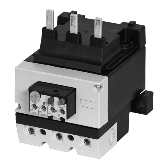
09/15 MN03407005Z-DE/EN Motorschutzrelais ZB65-…/XTOB…DC1 und ZB150-…/XTOB…GC1 Geräteübersicht Abbildung 1: Motorschutzrelais ZB65-…/XTOB…DC1 Abbildung 2: Motorschutzrelais ZB150-…/XTOB…GC1 Abbildung 3: Motorschutzrelais ZB150-…KK/XTOB…GC1S... -
Page 13: Gerätebeschreibung
09/15 MN03407005Z-DE/EN Gerätebeschreibung Gerätebeschreibung Überlastschutz mit Bimetallrelais Die Motorschutzrelais ZB65-…/XTOB…DC1 und ZB150-…/XTOB…GC1 sind dreipolige elektromechanische Motorschutzrelais mit Bimetallen. Sie sind zur Überwachung von Gleich- und Wechselstrom geeignet. Die Motorschutzrelais ZB65-…/XTOB…DC1 und ZB150-…/XTOB…GC1 sind als Direktanbau an die Schütze DIL einsetzbar. Direktanbau Motorschutzrelais Schütz... -
Page 14: Strombereiche Der Motorschutzrelais
09/15 MN03407005Z-DE/EN Motorschutzrelais ZB65-…/XTOB…DC1 und ZB150-…/XTOB…GC1 L1 L2 L3 (Q11/1) -S11 -Q11 -Q11 U V W Abbildung 4: Schaltbild eines Motorabgangs mit Motorschutzrelais Sicherung Motorschutzrelais Motorschütz Motor Strombereiche der Motorschutzrelais Die Motorschutzrelais werden mit Hilfe der Strom-Einstell- scheibe auf den Motornennstrom eingestellt. Mit entsprechenden Typen können Motoren von 6 bis 175 A Motornennstrom überwacht werden. - Page 15 09/15 MN03407005Z-DE/EN Gerätebeschreibung ZB65-…/XTOB…DC1 Tabelle 1: Strombereich der Relais Strombereich I [A] ZB65-10 XTOB010DC1 6 - 10 ZB65-16 XTOB016DC1 10 - 16 ZB65-24 XTOB024DC1 16 - 24 ZB65-40 XTOB040DC1 24 - 40 ZB65-57 XTOB057DC1 40 - 57 ZB65-65 XTOB065DC1 50 - 65 ZB65-75 XTOB075DC1 65 - 75...
-
Page 16: Temperaturkompensation
09/15 MN03407005Z-DE/EN Motorschutzrelais ZB65-…/XTOB…DC1 und ZB150-…/XTOB…GC1 Temperaturkompensation Zwei Parameter beeinflussen die Ausbiegung der Bimetalle: Zum einen die Wärme, die proportional zum fließenden Strom erzeugt wird, zum anderen die Umgebungstempe- ratur. Der Einfluss der Umgebungstemperatur wird mit Hilfe eines zusätzlichen Bimetalls, das nicht vom Motorstrom durch- flossen wird, im Temperaturbereich von -5 °C bis +55 °C kontinuierlich durch Korrektur des Auslöseweges selbsttätig kompensiert. -
Page 17: Wiedereinschaltung
09/15 MN03407005Z-DE/EN Gerätebeschreibung Soll mit einem Motorschutzrelais ZB…/XTOB… ein Wechselstrommotor oder ein Gleichstrommotor über- wacht werden, muss der Strom über alle drei Strom- bahnen geführt werden, um Frühauslösungen zu vermeiden. Abbildung 6: Verdrahtung der Motorschutzrelais für den Schutz von Wechselstrom- oder Gleichstrommotoren (Reihenschaltung der Bimetallauslöser) (a Abschnitt „Auslösekennlinien“... -
Page 18: Testfunktion
09/15 MN03407005Z-DE/EN Motorschutzrelais ZB65-…/XTOB…DC1 und ZB150-…/XTOB…GC1 Testfunktion Durch eine zusätzliche Testtaste kann die Funktionstüchtig- keit der Hilfsschalter kontrolliert werden. Hierbei hat die Testtaste eine Doppelfunktion: • Das Drücken der Testtaste öffnet den Öffner 95-96. Nach dem Loslassen fällt der Öffner wieder zurück. Diese Funktion kann zum manuellen Ausschalten des Motors genutzt werden. -
Page 19: Sicherheitstechnische Betrachtung
09/15 MN03407005Z-DE/EN Gerätebeschreibung Sicherheitstechnische Betrachtung Folgende Kenndaten für die funktionale Sicherheit wurden für die Motorschutzrelais ZB65-…/XTOB…DC1 und ZB150-…/XTOB…GC1 ermittelt: Für die Betriebsart mit niedriger Anforderungsrate und der Architektur 1oo1, bestehend aus Subsystemen nach Typ A und Hardware-Fehler-Toleranz (HFT) 0 (siehe EN 61508 Teil 1 Tabelle 3 und EN 61508 Teil 2 Tabelle 2) für die Motorschutzrelais bei einer Umgebungstemperatur von 55 °C:... - Page 20 09/15 MN03407005Z-DE/EN Motorschutzrelais ZB65-…/XTOB…DC1 und ZB150-…/XTOB…GC1 Mittlere Wahrscheinlichkeit eines gefahrbringenden Ausfalls bei Anforderung der Sicherheitsfunktion bei einem Intervall für die Wiederholungsprüfung von 36 Monaten: 1. Anforderungsrate F 1/Jahr (low demand mode): : 2,2 x 10 Die mittlere Betriebsdauer zwischen zwei Ausfällen (MTBF) beträgt: 43 Jahre.
-
Page 21: Projektierung
09/15 MN03407005Z-DE/EN Projektierung Überlastüberwachung von Durch besondere konstruktive Maßnahmen erreicht man bei Motoren im Ex e-Bereich Motoren die Zündschutzart Ex e. Den Motoren werden auf Basis der höchstzulässigen Oberflächentemperaturen Temperaturklassen zugeordnet. Zusätzlich werden die Erwärmungszeit t sowie das Verhältnis I von Anlauf- strom I zu Nennstrom I... - Page 22 09/15 MN03407005Z-DE/EN Projektierung Beispiel: I = 6, t = 10 s 7 8 9 10 Abbildung 7: Auslösekennlinie des Motorschutzrelais Der Motor wird zuverlässig geschützt.
-
Page 23: Kurzschlussschutz Der Motorschutzrelais
09/15 MN03407005Z-DE/EN Einstellung der Über- stromschutzeinrichtung Kurzschlussschutz der Motorschutzrelais Der Kurzschlussschutz der Motorschutzrelais wird durch Sicherungen realisiert. Bei Direktanbau an ein Schütz wird die Vorsicherung des Schützes für die entsprechende Zuord- nungsart mit berücksichtigt. Vorsicht! Zum Schutz von Ex e-Motoren ist nach EN 60947-4-1 nur die Zuordnungsart „2“... - Page 24 09/15 MN03407005Z-DE/EN Projektierung XTOB…GC1 Tabelle 4: ZB150-…/ in Direktanbau Schütz Sicherung gG/gL [A] Zuord- Zuord- nungsart „1“ nungsart „2“ ZB150-35 XTOB035GC1 DILM80 / XTCE080F ZB150-50 XTOB050GC1 DILM80 / XTCE080F ZB150-70 XTOB070GC1 DILM80 / XTCE080F ZB150-100 XTOB100GC1 DILM95 / XTCE095F ZB150-125 XTOB125GC1 DILM115 / XTCE115G ZB150-150...
-
Page 25: Zulassungen
09/15 MN03407005Z-DE/EN Zulassungen Zulassungen Die Motorschutzrelais ZB65-…/XTOB…DC1 und ZB150-…/XTOB…GC1 sind nach der Vorschrift IEC EN 60947 „Niederspannungsschaltgeräte“ gebaut und erfüllen die Forderungen nach der Richtlinie 94/9/EG (ATEX 100a) zum Schutz von Ex e-Motoren. Außerdem können nach EN 60079-14 Motoren in den Zonen 21 und 22 (Bereiche mit brennbarem Staub) geschützt werden. - Page 26 09/15 MN03407005Z-DE/EN...
-
Page 27: Installation
09/15 MN03407005Z-DE/EN Installation Hinweise zur Installation Bei der mechanischen und elektrischen Installation ist die entsprechende Montageanweisung zu beachten. Die Monta- geanweisung liegt den Relais ZB150-…/XTOB…GC1 bei; bei den Relais ZB65-…/XTOB…DC1 ist sie auf der Innen- seite der Kartonverpackung aufgedruckt. ZB65-…/XTOB…DC1: IL03407008Z (vormals AWA2300-2113) ZB150-…/XTOB…GC1: IL03407006Z (vormals AWA2300-2115) - Page 28 09/15 MN03407005Z-DE/EN Installation L1 L2 L3 (Q11/1) -S11 -Q11 -Q11 U V W Abbildung 8: Schaltung verhindert automatischen Wiederanlauf F1 Sicherung F2 Motorschutzrelais Q11 Leistungsschütz M1 Motor Die Selbsthaltung des Leistungsschützes Q11 verhindert einen automatischen Wiederanlauf. Die Funktion „Fernreset“ bzw. „Remote“ kann erzielt werden, indem das Motorschutzrelais auf AUTO gestellt wird.
-
Page 29: Geräte Montieren
09/15 MN03407005Z-DE/EN Geräte montieren Geräte montieren Die Motorschutzrelais ZB65-…/XTOB…DC1 können sowohl direkt am Schütz montiert als auch in Kombination mit der Einzelaufstellung aufgebaut werden. Die Relais ZB150-…/XTOB…GC1 sind für den Direktanbau an das Schütz gebaut; die Relais ZB150-…KK/XTOB…GC1S werden einzeln aufgestellt. Tabelle 6: Direktanbau Motorschutzrelais... - Page 30 09/15 MN03407005Z-DE/EN Installation ZB65-XEZ/ XTOBXDIND DIL.../ XTCE... ZB65/ XTOB...DC1 ZB65/ XTOB...DC1 Abbildung 9: Montage ZB65-…/XTOB…DC1 Die Einzelaufstellungen ZB65-XEZ/XTOBXDIND können auf einer Hutschiene oder direkt auf der Montageplatte montiert werden. DIL.../ XTCE... ZB150-.../ XTOB...GC1 Abbildung 10: Montage ZB150-…/XTOB…GC1...
- Page 31 09/15 MN03407005Z-DE/EN Geräte montieren Die Relais ZB150-…KK/XTOB…GC1S werden direkt auf die Montageplatte montiert. Tabelle 8: Maße zur Montage ZB65-XEZ/ ZB150-…KK/ XTOBXDIND XTOB…GC1S Bohrmaße (B x H) [mm] 50 x 75 100 x 74 Schraube [mm] 2 x (M5 x 12) 2 x (M6 x 20) Montage einer Plombierhaube Durch die Montage einer Plombierhaube...
- Page 32 09/15 MN03407005Z-DE/EN Installation Verdrahten Sie die Motorleitungen wie in Abb. 12. 1∼/ Abbildung 12: Hauptstromverdrahtung Folgende Leitungsquerschnitte sind möglich. Tabelle 10: Leitungsquerschnitte Hauptstrombahnen Hilfsstrombahnen ZB65-…/XTOB…DC1 ZB150-…/XTOB…GC1 95-96, 97-98 1 x (1 – 16) 1 x (4 – 16) 1 x (0,75 – 4) 2 x (1 –...
-
Page 33: Geräte Betreiben
09/15 MN03407005Z-DE/EN Geräte betreiben Einstellungen Vor der Erstinbetriebnahme des Motorschutzrelais muss der Motornennstrom mit Hilfe einer Stromeinstellscheibe am Relais eingestellt werden (a Tabelle 1 und Tabelle 2 auf Seite 11). Warnung! Bei einem kühlen Aufstellungsort des Motorschutzrelais (z. B. -5 °C) und einem warmen Aufstellungsort des Motors (z. -
Page 34: Test
09/15 MN03407005Z-DE/EN Geräte betreiben Test Die Motorschutzrelais ZB…/XTOB… sind mit einer Taste „Test“ versehen, in der eine Doppelfunktion integriert ist. TEST NO 97 NC 95 NO 98 NC 96 Abbildung 14: Schaltmöglichkeiten der Taste „Test“ Ein Ziehen der Taste hat das Öffnen des Hilfskontaktes 95-96 zur Folge und kann zum Abschalten des Schützes genutzt werden. -
Page 35: Overload Monitoring Of Ex E Motors
09/15 MN03407005Z-DE/EN Contents Motorschutzrelais ZB65/XTOB…DC1 und ZB150/XTOB…GC1 Überlastüberwachung von Ex e-Motoren Motor-protective relays ZB65/XTOB…DC1 and ZB150/XTOB…GC1 Overload monitoring of Ex e motors Anhang/Appendix About this manual Target group Abbreviations and symbols List of revisions ZB65-.../XTOB…DC1 and ZB150-.../XTOB…GC1 overload relays37 Foreword Device overview Description of device –... -
Page 36: Motorschutzrelais/Overload Relay
09/15 MN03407005Z-DE/EN Contents Using the device Settings – Reset – Test Anhang/Appendix Typenschilder/ Rating plates – Motorschutzrelais/Overload relay ZB65/XTOB…DC1 – Motorschutzrelais/Overload relay ZB150/XTOB…GC1 Auslösekennlinien/ Tripping characteristics – ZB65-10/XTOB010DC1 – ZB65-16/XTOB016DC1 – ZB65-24/XTOB024DC1 – ZB65-40/XTOB040DC1 – ZB65-57/XTOB057DC1 – ZB65-65/XTOB065DC1 – ZB65-75/XTOB075DC1 –... -
Page 37: About This Manual
09/15 MN03407005Z-DE/EN About this manual This manual applies to the ZB65/XTOB…DC1 and ZB150-.../XTOB…GC1 overload relays. It describes the overload monitoring system for the protection of motors operating in potentially explosive atmospheres Ex e areas. Target group This manual addresses qualified personnel who install, commission and service the motor overload relay. - Page 38 09/15 MN03407005Z-DE/EN About this manual Caution! warns of the possibility of serious damage and slight injury. Danger! warns of the possibility of serious damage and slight injury or death. For clarity of layout, we adhere to the following conventions in this manual: at the top of left-hand pages you will find the Chapter heading, at the top of right-hand pages the current Section heading;...
-
Page 39: List Of Revisions
09/15 Safety analysis Approvals Mounting a sealable shroud 01/11 General Inclusion of Eaton models General EEx e (now: Ex e) Notes about additional measures for motors in explosive dust-air mixtures EC prototype test certification numbers 61, 63 Rating Plates... - Page 40 09/15 MN03407005Z-DE/EN...
-
Page 41: Overload Relays37
09/15 MN03407005Z-DE/EN ZB65-.../XTOB…DC1 and ZB150-.../XTOB…GC1 overload relays Foreword In addition to the degree of protection specified in the standards EN 60079-14 and VDE 0165 Part 1, further provisions have been made to ensure safety from ignition for motors operated in potentially explosive atmospheres. EN 60079-7 prescribes additional measures to be taken for the operation motors with “increased safety”... -
Page 42: Device Overview
09/15 MN03407005Z-DE/EN ZB65-.../XTOB…DC1 and ZB150-.../XTOB…GC1 overload relays Device overview Figure 1: ZB65-…/XTOB…DC1 overload relays Figure 2: ZB150-…/XTOB…GC1 overload relays Figure 3: ZB150-…KK/XTOB…GC1S overload relays... -
Page 43: Description Of Device
09/15 MN03407005Z-DE/EN Description of device Description of device Overload protection with current transformer-oper- ated overload relay The ZB65-.../XTOB…DC1 and ZB150-.../XTOB…GC1 over- load relays are 3 pole electromechanical overload relays and are equipped with bimetallic releases. They are suitable both for AC and for DC operation. The ZB65-.../XTOB…DC1 and ZB150-.../XTOB…GC1 over- load relays can be mounted directly onto DIL contactor relays. -
Page 44: Current Ranges Of The Overload Relays
09/15 MN03407005Z-DE/EN ZB65-.../XTOB…DC1 and ZB150-.../XTOB…GC1 overload relays L1 L2 L3 (Q11/1) -S11 -Q11 -Q11 U V W Figure 4: Circuit diagram of the motor feeder with an overload relay Fuse Overload relay Motor contactor Motor Current ranges of the overload relays The overload relays are set to the rated current of the motor by means of a current setting dial. - Page 45 09/15 MN03407005Z-DE/EN Description of device Table 1: Current range of ZB65-…/XTOB…DC1 relays Type Current range I [A] ZB65-10 XTOB010DC1 6 - 10 ZB65-16 XTOB016DC1 10 - 16 ZB65-24 XTOB024DC1 16 - 24 ZB65-40 XTOB040DC1 24 - 40 ZB65-57 XTOB057DC1 40 - 57 ZB65-65 XTOB065DC1 50 - 65...
-
Page 46: Temperature Compensation
09/15 MN03407005Z-DE/EN ZB65-.../XTOB…DC1 and ZB150-.../XTOB…GC1 overload relays Temperature compensation Two parameters influence the deflection of the bimetallic releases: Firstly, the heat which is generated in proportion to the current flow, and secondly, the ambient air temperature. The influence of the ambient air temperature is automati- cally compensated within a temperature range from -5 °C to +55 °C by means of an additional current-free bimetallic release that continuously corrects the tripping range. -
Page 47: Re-Closing
09/15 MN03407005Z-DE/EN Description of device When a ZB…/XTOB… overload relay is to be used for monitoring an AC or DC motor, the current must flow across all three current paths in order to avoid early tripping. Figure 6: Wiring of the overload relay for the protection of AC or DC motors (bimetallic release switched in series) (a Section "Tripping characteristics"... -
Page 48: Test Function
09/15 MN03407005Z-DE/EN ZB65-.../XTOB…DC1 and ZB150-.../XTOB…GC1 overload relays Test function An additional Test button enables the operation of the auxiliary contact to be checked. The Test button has a dual function here: • When the button is pressed, the N/C contact 95-96 opens. It falls back again when the button is released. -
Page 49: Safety Analysis
09/15 MN03407005Z-DE/EN Description of device Safety analysis The following functional safety characteristics were determined for overload relays ZB65-…/XTOB…DC1 and ZB150-…/XTOB…GC1: For low demand operating mode with a 1oo1 architecture, consisting of type A subsystems and a hardware fault toler- ance (HFT) of 0 (see Table 3 in EN 61508 Part 1 and Table 2 in EN 61508 Part 2) for the overload relays at an ambient temperature of 55 °C: Motor protection (overload) - Page 50 09/15 MN03407005Z-DE/EN ZB65-.../XTOB…DC1 and ZB150-.../XTOB…GC1 overload relays Average probability of a dangerous failure when the safety function is on demand, using an interval of 36 months for repeat test: 1st demand level F 1/year (low demand mode): : 2.2 x 10 The mean lifespan between two failures (MTBF) is 43 years.
-
Page 51: Projection
09/15 MN03407005Z-DE/EN Projection Overload monitoring of The Ex e protection of motors is achieved by means of motors in the Ex e area special design measures. The motors are assigned to temper- ature classes on the basis of the highest permissible surface temperatures. - Page 52 09/15 MN03407005Z-DE/EN Projection Example: I = 6, t = 10 s 7 8 9 10 Figure 7: Tripping characteristic of the overload relay The motor is reliably protected.
-
Page 53: Short-Circuit Protection Of The Overload Relays
09/15 MN03407005Z-DE/EN Adjusting the overload current protection Short-circuit protection of the overload relays The overload relays are short-circuit protected by means of fuses. When the relay is mounted directly onto a contactor relay, the corresponding primary fuse of the contactor relay is taken into account accordingly. - Page 54 09/15 MN03407005Z-DE/EN Projection Table 4: ZB150-…/XTOB…GC1 direct mounting Type Contactor Fuse gG/gL [A] Type of coor- Type of coor- dination “1” dination “2” ZB150-35 XTOB035GC1 DILM80 / XTCE080F ZB150-50 XTOB050GC1 DILM80 / XTCE080F ZB150-70 XTOB070GC1 DILM80 / XTCE080F ZB150-100 XTOB100GC1 DILM95 / XTCE095F ZB150-125 XTOB125GC1...
-
Page 55: Approvals
09/15 MN03407005Z-DE/EN Approvals Approvals The ZB65-.../XTOB…DC1 and ZB150-.../XTOB…GC1 over- load relays are compliant with IEC EN 60947 regulations for “low-voltage switchgear” and meet the requirements of the 94/9/EU (ATEX 100a) directives for the protection of Ex e motors. Furthermore, motors can be explosion protected in zones 21 and 22 (areas with combustible dusts) in compliance with EN 60079-14. - Page 56 09/15 MN03407005Z-DE/EN...
-
Page 57: Installation
09/15 MN03407005Z-DE/EN Installation Installation instructions The mechanical and electrical instruction leaflet must be observed. The instructional leaflet is included with the ZB150-.../XTOB…GC1 relays. For the ZB65-.../XTOB…DC1 relays, these instructions are imprinted on the inside of the cardboard packing. ZB65-…/XTOB…DC1: IL03407008Z (former AWA2300-2113) ZB150-…/XTOB…GC1: IL03407006Z (former AWA2300-2115) - Page 58 09/15 MN03407005Z-DE/EN Installation L1 L2 L3 (Q11/1) -S11 -Q11 -Q11 U V W Figure 8: Circuit prevents automatic restart F1 Fuse F2 Overload relay Q11 Contactor relay M1 Motor The latching function of the Q11 contactor relay prevents an automatic restart. The “remote reset“/ “remote”...
-
Page 59: Fitting The Device
09/15 MN03407005Z-DE/EN Fitting the device Fitting the device The ZB65-…/XTOB…DC1 overload relays can either be mounted directly onto the contactor relay, or in combination with the single-mount assembly. relays are designed for ZB150-…/XTOB…GC1 direct mounting to the contactor, whereas the ZB150-…KK/XTOB…GC1S relays are installed individually. - Page 60 09/15 MN03407005Z-DE/EN Installation ZB65-XEZ/ XTOBXDIND DIL.../ XTCE... ZB65/ XTOB...DC1 ZB65/ XTOB...DC1 Figure 9: Mounting the ZB65-…/XTOB…DC1 The single-mount assemblies ZB65-XEZ/XTOBXDIND can be mounted individually on DIN rail or directly on a mounting panel. DIL.../ XTCE... ZB150-.../ XTOB...GC1 Figure 10: Mounting the ZB150-.../XTOB…GC1...
- Page 61 09/15 MN03407005Z-DE/EN Fitting the device The ZB150-…KK/XTOB…GC1S relays are mounted directly on a mounting panel. Table 8: Mounting dimensions ZB65-XEZ/ ZB150-…KK/ XTOBXDIND XTOB…GC1S Bore dimensions (W x H) [mm] 50 x 75 100 x 74 Screw [mm] 2 x (M5 x 12) 2 x (M6 x 20) Mounting a sealable shroud To prevent changes from being made to the overload setting,...
- Page 62 09/15 MN03407005Z-DE/EN Installation Connect the motor cables as shown in Fig. 12. 1∼/ Figure 12: Main circuit wiring The following cable cross sections are possible. Table 10: Cable cross-sections Main circuits Auxiliary circuits ZB65-…/XTOB…DC1 ZB150-…/XTOB…GC1 95-96, 97-98 1 x (1 – 16) 1 x (4 –...
-
Page 63: Using The Device
09/15 MN03407005Z-DE/EN Using the device Settings Prior to initial commissioning, the rated motor current must be set on the overload relay by means of the current dial (a Table 1 and Table 2 on Page 41). Warning! If the overload relay is installed at a cool location (e.g. -
Page 64: Test
09/15 MN03407005Z-DE/EN Using the device Test The ZB…/XTOB… overload relays are equipped with a Test button that has an integral dual function. TEST NO 97 NC 95 NO 98 NC 96 Figure 14: Switching options of the Test button The auxiliary contact 95-96 is opened by pulling the Test button, and can thus be used to switch off the contactor relay. -
Page 65: Anhang/Appendix
09/15 MN03407005Z-DE/EN Anhang/Appendix Typenschilder/ Motorschutzrelais/Overload relay ZB65/XTOB…DC1 Rating plates IEC/EN 60947-4-1 6000 V 690 V ~ max. Type "1" A gL/gG max. Type "2" A gL/gG IEC/EN 60947-5-1 Normal Test AC-15 U 220/240 380/415 500 95-96 97-98 0102 II(2)G [Ex d][Ex e][Ex px] II(2)D [Ex p][Ex t] GB 14048.4 PTB 10 ATEX 3010... - Page 66 09/15 MN03407005Z-DE/EN Anhang/Appendix Tabelle/Table 11: Werte der einzelnen Typen/Values of the various types ZB65-10 XTOB010DC1 ZB65-16 XTOB016DC1 ZB65-24 XTOB024DC1 ZB65-40 XTOB040DC1 ZB65-57 XTOB057DC1 ZB65-65 XTOB065DC1 ZB65-75 XTOB075DC1...
-
Page 67: Motorschutzrelais/Overload Relay Zb150/Xtob
09/15 MN03407005Z-DE/EN Typenschilder/ Rating plates Motorschutzrelais/Overload relay ZB150/XTOB…GC1 IEC/EN 60947-4-1 6000 V 690 V ~ max. Type "1" A gL/gG max. Type "2" A gL/gG IEC/EN 60947-5-1 Normal Test AC-15 U 220/240 380/415 500 95-96 97-98 0102 II(2)G [Ex d][Ex e][Ex px] II(2)D [Ex p][Ex t] GB 14048.4 PTB 10 ATEX 3010... - Page 68 09/15 MN03407005Z-DE/EN Anhang/Appendix Die Zuordnungen der Werte zu den jeweiligen Typen sind der nachfolgenden Tabelle 12 zu entnehmen. For information on the assignment of values to the relevant types, please refer to table 12. Tabelle/Table 12: Werte der einzelnen Typen/Values of the various types ZB150-35 XTOB035GC1...
-
Page 69: Auslösekennlinien/Tripping Characteristics
09/15 MN03407005Z-DE/EN Auslösekennlinien/ Tripping characteristics Auslösekennlinien/ Tripping characteristics... -
Page 70: Zb65-10/Xtob010Dc1
09/15 MN03407005Z-DE/EN Anhang/Appendix ZB65-10/XTOB010DC1 Bereich/Range 6 - 10 A (NM - HM) Umgebungstemperatur/Ambient temperature 20 °C Auslöseklasse/Tripping class 10 A Toleranzbereich/Tolerance range g20 % Einstellung/ Auslösezeit/Tripping time t [s] Setting 3-phase a 2-phase c 3-phase b 2-phase d 3 x I 16.5 7.2 x I 7 8 9 10... -
Page 71: Zb65-16/Xtob016Dc1
09/15 MN03407005Z-DE/EN Auslösekennlinien/ Tripping characteristics ZB65-16/XTOB016DC1 Bereich/Range 10 - 16 A (NM - HM) Umgebungstemperatur/Ambient temperature 20 °C Auslöseklasse/Tripping class 10 A Toleranzbereich/Tolerance range g20 % Einstellung/ Auslösezeit/Tripping time t [s] Setting 3-phase a 2-phase c 3-phase b 2-phase d 3 x I 29.7 7.2 x I... -
Page 72: Zb65-24/Xtob024Dc1
09/15 MN03407005Z-DE/EN Anhang/Appendix ZB65-24/XTOB024DC1 Bereich/Range 16 - 24 A (NM - HM) Umgebungstemperatur/Ambient temperature 20 °C Auslöseklasse/Tripping class 10 A Toleranzbereich/Tolerance range g20 % Einstellung/ Auslösezeit/Tripping time t [s] Setting 3-phase a 2-phase c 3-phase b 2-phase d 3 x I 24.5 7.2 x I 7 8 9 10... -
Page 73: Zb65-40/Xtob040Dc1
09/15 MN03407005Z-DE/EN Auslösekennlinien/ Tripping characteristics ZB65-40/XTOB040DC1 Bereich/Range 24 - 40 A (NM - HM) Umgebungstemperatur/Ambient temperature 20 °C Auslöseklasse/Tripping class 10 A Toleranzbereich/Tolerance range g20 % Einstellung/ Auslösezeit/Tripping time t [s] Setting 3-phase a 2-phase c 3-phase b 2-phase d 3 x I 23.5 18.2... -
Page 74: Zb65-57/Xtob057Dc1
09/15 MN03407005Z-DE/EN Anhang/Appendix ZB65-57/XTOB057DC1 Bereich/Range 40 - 57 A (NM - HM) Umgebungstemperatur/Ambient temperature 20 °C Auslöseklasse/Tripping class 10 A Toleranzbereich/Tolerance range g20 % Einstellung/ Auslösezeit/Tripping time t [s] Setting 3-phase a 2-phase c 3-phase b 2-phase d 3 x I 28.8 16.6 7.2 x I... -
Page 75: Zb65-65/Xtob065Dc1
09/15 MN03407005Z-DE/EN Auslösekennlinien/ Tripping characteristics ZB65-65/XTOB065DC1 Bereich/Range 50 - 65 A (NM - HM) Umgebungstemperatur/Ambient temperature 20 °C Auslöseklasse/Tripping class 10 A Toleranzbereich/Tolerance range g20 % Einstellung/ Auslösezeit/Tripping time t [s] Setting 3-phase a 2-phase c 3-phase b 2-phase d 3 x I 26.4 18.5... -
Page 76: Zb65-75/Xtob075Dc1
09/15 MN03407005Z-DE/EN Anhang/Appendix ZB65-75/XTOB075DC1 Bereich/Range 65 - 75 A (NM - HM) Umgebungstemperatur/Ambient temperature 20 °C Auslöseklasse/Tripping class 10 A Toleranzbereich/Tolerance range g20 % Einstellung/ Auslösezeit/Tripping time t [s] Setting 3-phase a 2-phase c 3-phase b 2-phase d 3 x I 26.4 18.5 23.9... -
Page 77: Zb150-35/Xtob35Gc1, Zb150-35Kk/Xtob035Gc1S
09/15 MN03407005Z-DE/EN Auslösekennlinien/ Tripping characteristics ZB150-35/XTOB35GC1, ZB150-35KK/XTOB035GC1S Bereich/Range 25 - 35 A (NM - HM) Umgebungstemperatur/Ambient temperature 20 °C Auslöseklasse/Tripping class 10 A Toleranzbereich/Tolerance range g20 % Einstellung/ Auslösezeit/Tripping time t [s] Setting 3-phase a 2-phase c 3-phase b 2-phase d 3 x I 7.2 x I 7 8 9 10... -
Page 78: Zb150-50/Xtob050Gc1
09/15 MN03407005Z-DE/EN Anhang/Appendix ZB150-50/XTOB050GC1 Bereich/Range 35 - 50 A (NM - HM) Umgebungstemperatur/Ambient temperature 20 °C Auslöseklasse/Tripping class 10 A Toleranzbereich/Tolerance range g20 % Einstellung/ Auslösezeit/Tripping time t [s] Setting 3-phase a 2-phase c 3-phase b 2-phase d 3 x I 15.8 13.8 7.2 x I... -
Page 79: Zb150-50Kk/Xtob050Gc1S
09/15 MN03407005Z-DE/EN Auslösekennlinien/ Tripping characteristics ZB150-50KK/XTOB050GC1S Bereich/Range 36 - 50 A (NM - HM) Umgebungstemperatur/Ambient temperature 20 °C Auslöseklasse/Tripping class 10 A Toleranzbereich/Tolerance range g20 % Einstellung/ Auslösezeit/Tripping time t [s] Setting 3-phase a 2-phase c 3-phase b 2-phase d 3 x I 12.8 7.2 x I... -
Page 80: Zb150-70/Xtob070Gc1, Zb150-70Kk/Xtob070Gc1S
09/15 MN03407005Z-DE/EN Anhang/Appendix ZB150-70/XTOB070GC1, ZB150-70KK/XTOB070GC1S Bereich/Range 50 - 70 A (NM - HM) Umgebungstemperatur/Ambient temperature 20 °C Auslöseklasse/Tripping class 10 A Toleranzbereich/Tolerance range g20 % Einstellung/ Auslösezeit/Tripping time t [s] Setting 3-phase a 2-phase c 3-phase b 2-phase d 3 x I 15.3 7.2 x I 7 8 9 10... -
Page 81: Zb150-100/Xtob100Gc1
09/15 MN03407005Z-DE/EN Auslösekennlinien/ Tripping characteristics ZB150-100/XTOB100GC1 Bereich/Range 70 - 100 A (NM - HM) Umgebungstemperatur/Ambient temperature 20 °C Auslöseklasse/Tripping class 10 A Toleranzbereich/Tolerance range g20 % Einstellung/ AuslösezeitTripping time t [s] Setting 3-phase a 2-phase c 3-phase b 2-phase d 3 x I 7.2 x I 7 8 9 10... -
Page 82: Zb150-100Kk/Xtob100Gc1S
09/15 MN03407005Z-DE/EN Anhang/Appendix ZB150-100KK/XTOB100GC1S Bereich/Range 70 - 100 A (NM - HM) Umgebungstemperatur/Ambient temperature 20 °C Auslöseklasse/Tripping class 10 A Toleranzbereich/Tolerance range g20 % Einstellung/ Auslösezeit/Tripping time t [s] Setting 3-phase a 2-phase c 3-phase b 2-phase d 3 x I 7.2 x I 7 8 9 10 Abbildung/Figure 29: ZB150-100KK/XTOB100GC1S... -
Page 83: Zb150-125/Xtob125Gc1, Zb150-125Kk/Xtob125Gc1S
09/15 MN03407005Z-DE/EN Auslösekennlinien/ Tripping characteristics ZB150-125/XTOB125GC1, ZB150-125KK/XTOB125GC1S Bereich/Range 95 - 125 A (NM - HM) Umgebungstemperatur/Ambient temperature 20 °C Auslöseklasse/Tripping class 10 A Toleranzbereich/Tolerance range g20 % Einstellung/ Auslösezeit/Tripping time t [s] Setting 3-phase a 2-phase c 3-phase b 2-phase d 3 x I 24.5 7.2 x I... -
Page 84: Zb150-150/Xtob150Gc1
09/15 MN03407005Z-DE/EN Anhang/Appendix ZB150-150/XTOB150GC1 Bereich/Range 120 - 150 A (NM - HM) Umgebungstemperatur/Ambient temperature 20 °C Auslöseklasse/Tripping class 10 A Toleranzbereich/Tolerance range g20 % Einstellung/ Auslösezeit/Tripping time t [s] Setting 3-phase a 2-phase c 3-phase b 2-phase d 3 x I 7.2 x I 7 8 9 10 Abbildung/Figure 31: ZB150-150/XTOB150GC1... -
Page 85: Zb150-150Kk/Xtob150Gc1S
09/15 MN03407005Z-DE/EN Auslösekennlinien/ Tripping characteristics ZB150-150KK/XTOB150GC1S Bereich/Range 120 - 150 A (NM - HM) Umgebungstemperatur/Ambient temperature 20 °C Auslöseklasse/Tripping class 10 A Toleranzbereich/Tolerance range g20 % Einstellung/ Auslösezeit/Tripping time t [s] Setting 3-phase a 2-phase c 3-phase b 2-phase d 3 x I 7.2 x I 7 8 9 10... -
Page 86: Zb150-175/Xtob175Gc1
09/15 MN03407005Z-DE/EN Anhang/Appendix ZB150-175/XTOB175GC1 Bereich/Range 145 - 175 A (NM - HM) Umgebungstemperatur/Ambient temperature 20 °C Auslöseklasse/Tripping class 10 A Toleranzbereich/Tolerance range g20 % Einstellung/ Auslösezeit/Tripping time t [s] Setting 3-phase a 2-phase c 3-phase b 2-phase d 3 x I 7.2 x I 7 8 9 10 Abbildung/Figure 33: ZB150-175/XTOB175GC1... -
Page 87: Zb150-175Kk/Xtob175Gc1S
09/15 MN03407005Z-DE/EN Auslösekennlinien/ Tripping characteristics ZB150-175KK/XTOB175GC1S Bereich/Range 145 - 175 A (NM - HM) Umgebungstemperatur/Ambient temperature 20 °C Auslöseklasse/Tripping class 10 A Toleranzbereich/Tolerance range g20 % Einstellung/ Auslösezeit/Tripping time t [s] Setting 3-phase a 2-phase c 3-phase b 2-phase d 3 x I 7.2 x I 7 8 9 10... -
Page 88: Eg-Konformitätserklärung/Declaration Of Ec Conformity (Doc. No.: Ce1400094) Zb65
Anhang/Appendix EG-Konformitätserklärung/Declaration of EC Conformity (Doc. No.: CE1400094) ZB65 EG-Konformitätserklärung Declaration of EC Conformity Wir / We, Eaton Industries GmbH Hein-Moeller-Str. 7-11, 53115 Bonn (Germany) erklären hiermit, dass das Produkt (die Produktfamilie) declare that the product (family) ZB65 entsprechend der Auflistung auf Seite 2 und vorausgesetzt, dass es unter Berücksichtigung der relevanten Herstellerangaben, Einbauanweisungen und... - Page 89 09/15 MN03407005Z-DE/EN EG-Konformitätserklärung/ Declaration of EC Conformity (Doc. No.: CE1400094) ZB65 EG-Konformitätserklärung/Declaration of EC Conformity (Doc. No.: CE1400094) ZB65 Typen des Sortiments Types within the range Die Konformitätserklärung gilt für folgende Typen der Produktfamilie und in Kombination mit den darunter folgenden Produkten: The declaration of conformity applies to the following types within the product family and in combination with products listed below: ZB65-XEZ...
-
Page 90: Eg-Konformitätserklärung/Declaration Of Ec Conformity (Doc. No.: Ce1400092) Zb150
Anhang/Appendix EG-Konformitätserklärung/Declaration of EC Conformity (Doc. No.: CE1400092) ZB150 EG-Konformitätserklärung Declaration of EC Conformity Wir / We, Eaton Industries GmbH Hein-Moeller-Str. 7-11, 53115 Bonn (Germany) erklären hiermit, dass das Produkt (die Produktfamilie) declare that the product (family) ZB150 entsprechend der Auflistung auf Seite 2 und vorausgesetzt, dass es unter Berücksichtigung der relevanten Herstellerangaben, Einbauanweisungen und... - Page 91 09/15 MN03407005Z-DE/EN EG-Konformitätserklärung/ Declaration of EC Conformity (Doc. No.: CE1400092) ZB150 EG-Konformitätserklärung/Declaration of EC Conformity (Doc. No.: CE1400092) ZB150 Typen des Sortiments Types within the range Die Konformitätserklärung gilt für folgende Typen der Produktfamilie und in Kombination mit den darunter folgenden Produkten: The declaration of conformity applies to the following types within the product family and in combination with products listed below: / Supplementary Notes:...
- Page 92 09/15 MN03407005Z-DE/EN...
Need help?
Do you have a question about the ZB65 Series and is the answer not in the manual?
Questions and answers