SonoSite M-Turbo Service Manual
Hide thumbs
Also See for M-Turbo:
- User manual (280 pages) ,
- Quick start manual (14 pages) ,
- Quick manual (2 pages)
Table of Contents
Advertisement
Advertisement
Table of Contents

Subscribe to Our Youtube Channel
Related Manuals for SonoSite M-Turbo


Summary of Contents for SonoSite M-Turbo
- Page 1 M-Turbo Ultrasound System Service Manual...
- Page 2 Federal (United States) law restricts this device to sale by or on the order of a physician. M-Turbo, SiteLink, SonoCalc, SonoHD, SonoMB, and SonoSite are registered trademarks or trademarks of SonoSite, Inc. DICOM is the registered trademark of the National Electrical Manufacturers Association for its standards publications relating to digital communications of medical information.
-
Page 3: Table Of Contents
Contents Chapter 1: Introduction Audience ........................... 1 Conventions ........................1 Contact Information ..................... 1 Chapter 2: System Overview About the System ......................3 Theory of Operation ..................... 4 Description of Operating Modes ..............5 Additional System Feature Performances ........... 7 ECG Module ...................... - Page 4 Control Panel .........................42 System ..........................43 Transducer Nest Frame Assembly .................46 Ordering Replacement Parts ...................46 Appendix B: Service Event Report Service Event Report Form ..................48 Service Event Report Instructions .................49 Returning Products to SonoSite ................50 Shipping Instructions ..................50 Index ........................51...
-
Page 5: Chapter 1: Introduction
Chapter 1: Introduction Before servicing the M-Turbo ultrasound system, please read this manual. The information applies only to the SonoSite M-Turbo ultrasound system product manufactured after December 5, 2007. The ultrasound system has multiple configurations and feature sets. All are described in this service manual but not every option may apply to your system. - Page 6 Chapter 1: Introduction...
-
Page 7: Chapter 2: System Overview
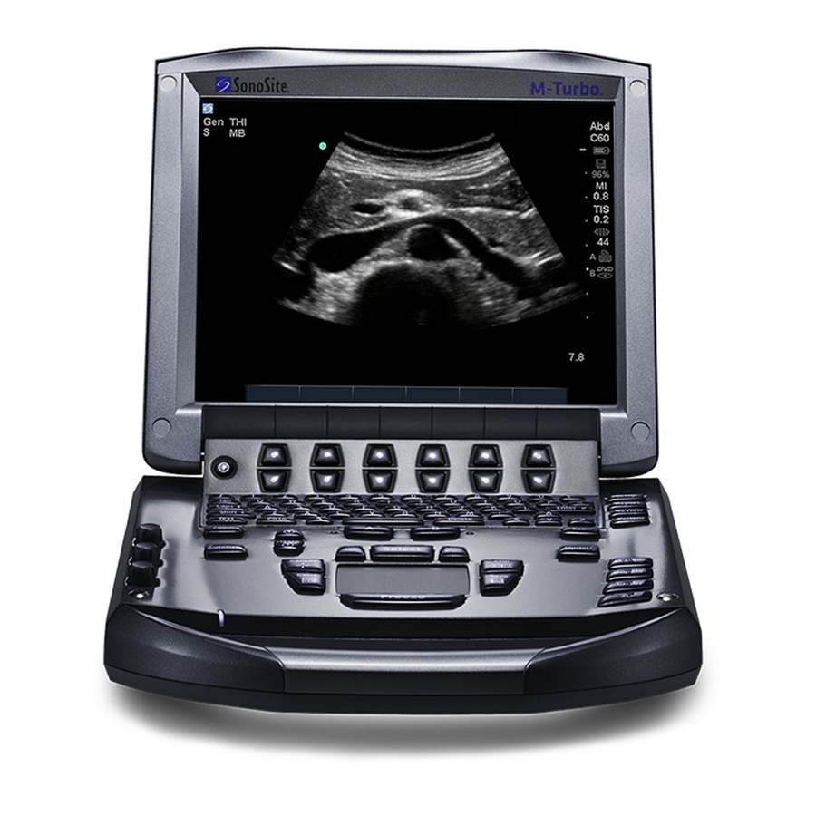
Chapter 2: System Overview About the System The SonoSite M-Turbo high-resolution ultrasound system is a portable, full featured, general purpose, software controlled, diagnostic ultrasound system using all digital architecture. The system is used to acquire and display high-resolution, real-time ultrasound data in 2D, M Mode, Pulsed Wave (PW) Doppler, Continuous Wave (CW) Doppler, Color Power Doppler (CPD), and color Doppler (Color) or in a combination of these modes. -
Page 8: Theory Of Operation
Theory of Operation The M-Turbo ultrasound system has seven (7) major functional groups: • Transducer • Acquisition Subsystem • Processing Subsystem • Display Subsystem • Control Subsystem • User Interface Subsystem • Power Subsystem Figure 2.1 is a system block diagram that shows the relationship of the functional groups. -
Page 9: Description Of Operating Modes
The Display Subsystem converts the detected ultrasound data into picture elements (pixels). The software user interface graphics are combined with the ultrasound information and converted to a video stream. The external video port supports NTSC and PAL format. The Control Subsystem consists of the central processing unit, program and video memory, permanent image storage and retrieval memory, external communication interface ports, and connection to the user interface keys. - Page 10 Color In color Doppler, a real-time, two-dimensional cross-section of blood flow is displayed. The Doppler 2D cross-section may be presented as a rectangle, parallelogram, trapezoid, sector, or a full (Color) circle, depending on the particular transducer used. The 2D cross-section is presented as a full color display, with various colors being used to represent the velocity, both positive and negative, of the blood flow echoes.
-
Page 11: Additional System Feature Performances
Pulsed Wave PW provides a real-time representation of blood flow and is displayed as a (PW) Doppler velocity-versus-time sweeping output. Velocity (or frequency) is presented as the vertical axis with time along the horizontal axis. The magnitude of the detected signal is represented as different gray scale values. -
Page 12: Ecg Module
System Specifications This section contains system and accessory specifications and agency approvals. The specifications for recommended peripherals can be found in the manufacturers’ instructions. See the applicable SonoSite accessory user guide for information on the accessories. Chapter 2: System Overview... -
Page 13: System Dimensions
System Dimensions Length: 11.8 in. (29.97 cm) Width: 10.8 in. (27.43 cm) Height: 3.1 in. (7.87 cm) Weight: 8.5 lbs. (3.9 kg) with the C60x transducer and battery installed Display Dimensions Length: 8.4 in. (21.34 cm) Height: 6.3 in. (16 cm) Diagonal: 10.4 in. -
Page 14: Peripherals
Triple Transducer Connect Video and printer cables Cables See the M-Turbo Ultrasound System User Guide, MDSm User Guide, and the MDS Lite II User Guide for information on cables. Peripherals Peripherals include the following medical grade (conforming to the requirements of EN60601-1) and non-medical grade (commercial) products. -
Page 15: Temperature, Pressure, And Humidity Limits
Temperature, Pressure, and Humidity Limits Note: The temperature, pressure, and humidity limits apply only to the ultrasound system and transducers. Operating Limits: System • 10–40°C (50–104°F), 15–95% R.H. • 700 to 1060hPa (0.7 to 1.05 ATM) Operating Limits: Battery • 10–40°C (50–104°F), 15–95% R.H. •... -
Page 16: Electromechanical Safety Standards
CISPR11:2004, International Electrotechnical Commission, International Special Committee on Radio Interference. Industrial, Scientific, and Medical (ISM) Radio-Frequency Equipment Electromagnetic Disturbance Characteristics-Limits and Methods of Measurement. The Classification for the SonoSite system, SiteStand, accessories, and peripherals when configured together is: Group 1, Class A. Airborne Equipment Standards RTCA/DO]160E:2004, Radio Technical Commission for Aeronautics, Environmental Conditions and Test Procedures for Airborne Equipment, Section 21.0 Emission of Radio Frequency Energy, Category B. -
Page 17: Chapter 3: Troubleshooting
System and Subsystem Diagnosis This section covers basic diagnostic and troubleshooting procedures you may follow if the system does not operate properly. To diagnose system failures, consult the referenced diagnostic figures that follow or SonoSite Technical Support. Table 3.1: Troubleshooting Subassemblies and Diagnostic Figures... -
Page 18: Failure (Assert) Codes
• If the assert condition remains, corrective action must be taken; usually replacement of the main PCBA is required. Contact SonoSite Technical Support for assistance and to obtain repair parts. If the Power button is not functional, all sources of power must be removed to allow the system to power down. -
Page 19: Dicom
Image settings. E.g,. failed Color (RGB) or Grayscale (Monochrome) DICOM network TDNETWORK_OPEN_FAILURE Device does not Verify that M-Turbo AE Title or IP communication recognize address is correctly configured on failed M-Turbo, rejects the Printer/Archiver. association Note: Some devices require that the... - Page 20 Chapter 3: Troubleshooting...
-
Page 21: Chapter 4: Replacement Procedures
Caution: All fasteners should be torqued to 5.5 inch pounds except where noted. Display Replacement Required Parts Service Assembly, LCD Display, M-Turbo (P08659) Required Tools • #1 Phillips screwdriver • Torque screwdriver, 2.0–10.0 inch pounds (0.23–1.1 newton meter) • An anti-static mat •... - Page 22 Lay the system on the top, and remove the two screws from the bottom of the system per Figure 4.2. Screws (2) Figure 4.2 System Bottom Turn the system over, fully open the display, and lift off the Control Panel per Figure 4.3.
- Page 23 Disconnect the two connectors from the display to the Main PCBA per Figure 4.4. Connectors (2) Figure 4.4 Display Connectors The replacement Display Assembly does not include the Display Rear Enclosure. Remove the Display Rear Enclosure by removing the two screw caps, two screws, and then sliding the rear enclosure up and away from the display as show in Figure 4.5.
-
Page 24: Display Replacement
Remove the four screws from the Display Hinges per Figure 4.6. Screws (4) Figure 4.6 Display Screws Display Replacement Display Set the new display in place. Replacement Install the four hinge screws that hold the Display in place. Torque the screws to 5.5 inch pounds. -
Page 25: Control Panel Subassembly Replacement
Control Panel Subassembly Replacement Required Parts One of the following: • P08856 Service Assembly, Control Panel M-Turbo, English • P08878 Service Assembly, Control Panel M-Turbo, French • P08879 Service Assembly, Control Panel M-Turbo, German • P08880 Service Assembly, Control Panel M-Turbo, Italian •... -
Page 26: Main System Disassembly For Repair And/Or Replacement
• P08939 Service Assembly Main PCBA, M-Turbo • P08850 Service Assembly Power Supply, M-Turbo • P05470 Service Assembly TGC, MicroMaxx (compatible with MicroMaxx and M-Turbo) • P05473 Service Assembly Speaker, M-Turbo • Nest Frame Assembly, M-Turbo (order these parts individually as necessary) •... - Page 27 Major System Components Main PCBA SD Card Daughter-card Nest frame assembly Power supply TGC assembly Speaker Speaker Figure 4.7 System Components Speaker Replacement Caution: Use caution when removing the left speaker connector to prevent damage to the Main PCBA components around the connector. Speaker Press on the connector release and pull the connector out of the receptacle.
- Page 28 Power Supply PCBA Replacement Power Supply Gently pry the shield from the power supply and set it aside. This part will be used in Removal reassembly. Note that the shield fits only one way. See Figure 4.9. Power supply shield Figure 4.9 Power Supply Shield Remove the 7 screws that hold down the power supply PCB per Figure...
- Page 29 SD Card Daughter-card SD Card Carefully remove the copper tape from the SD Card Daughter-card. See Figure 4.11. Daughter-card Removal SD Card Daughter-card under copper tape Figure 4.11 SD Card Daughter-card copper tape Remove the 4 screws that hold down the SD Card Daughter-card per Figure 4.12.
- Page 30 SD Card Remove Power Supply frame assembly from the Main PCBA. Daughter-card Apply one strip of 1” x 5” self adhesive copper tape to the edge of the Power Supply frame Replacement as shown in Figure 4.13. The copper tape must be cut away from the ventilation holes in the frame or failure of the Main PCBA will occur.
- Page 31 Figure 4.14 SD Card Daughter-card alignment Fold the copper strip installed in Step 1 over the top of the SD Card Daughter-card. Install a second strip of 1” x 5” self-adhesive copper tape over the SD Card Daughter-card on the edge closest to the Power Supply frame as show in Figure 4.15.
- Page 32 Note: Rub the entire surface of the copper tape to ensure proper adhesion. Figure 4.17 Activating Copper Tape Adhesive TGC PCBA Replacement TGC PCBA Remove the Control Panel if not already removed. Removal Remove the TGC knobs identified in Figure 4.18.
- Page 33 Remove the flex cable from the TGC PCB by lifting on the flex release tab. See Figure 4.19. Remove the flex cable from the Main PCBA by lifting gently on the flex release tab. Remove the two screws holding the TGC PCBA in place. Reverse steps 1-5 to reinstall the TGC PCB.
- Page 34 2.5mm Socket Head Cap Screws (4x) Figure 4.21 Nest Frame Top Screws Turn the system over. Remove the 4 Socket Head Cap Screw as shown in Figure 4.21. This releases the Nest Frame and will allow the Main PCBA to be removed. As you remove the nest frame assembly from the PCBA, tilt the PCBA and enclosure to almost vertical to avoid spilling the Interposer Connectors from the assembly.
- Page 35 Main PCBA Replace the Main PCBA by following the reverse of the removal procedure. Do not tighten all the Replacement screws until everything is in place. Replace the Main PCBA. Reinstall the Nest Frame Assembly. The Nest Frame Socket Head Cap Screws should be torqued to 4.5 inch pounds Reconnect the speaker wires.
- Page 36 Chapter 4: Replacement Procedures...
-
Page 37: Chapter 5: Performance Testing
To obtain 2D images, SonoSite recommends using the RMI 413A Soft Tissue Phantom or the RMI 403 GS Multipurpose Phantom. A .7db/cm phantom is required for performing penetration measurements. Any equivalent .7db/cm Phantom is acceptable. -
Page 38: Basic Operational Tests
Basic Operational Tests Basic System Verify that the correct transducer name appears in the upper right corner of the system Operation display. Tests Verify proper date and time. Verify that the scan plane orientation mark in the image located near the skinline corresponds to element #1 on the transducer. -
Page 39: Axial Measurement Accuracy
Measurement Press the Freeze key. Accuracy Press the Caliper key. The caliper appears on the image display. (See the M-Turbo Ultrasound System User Guide, if necessary, for caliper operation.) Use the touchpad to position one of the calipers. Press the Select key to fix the caliper and enable the other caliper. -
Page 40: Additional Performance Tests
Table 5.2: Imaging Performance Imaging C11x C60x ICTx HFL38 L25x L38x P21x Performance Exam type Nerve Small Breast Parts Optimization 2D Penetration 6.8cm 14.0 cm 6.5 cm 4.5 cm 4.3 cm 5.7 cm 21.0 cm Additional Performance Tests Color Doppler (Color) Test Color Connect any transducer. -
Page 41: M Mode Imaging
M Mode Imaging Test M Mode Attach a C60x transducer and acquire an image. Imaging Press the M Mode key for the M Mode sample line. Position the M Mode sample line over the image using the touchpad. Press the M Mode key again to turn on M Mode. Select the desired sweep speed from the on-screen menu (slow, med, or fast). -
Page 42: Continuous Wave (Cw) Doppler Imaging
Continuous Wave (CW) Doppler Imaging Test CW Attach the P21x transducer. Doppler Press the Patient key. Imaging Select the Cardiac exam type. Press the Done softkey. Press the Doppler key for the Doppler sample gate. Press the PW softkey to switch to CW Mode. Press the Doppler key again for the Doppler spectral trace. -
Page 43: Battery Charging
Battery Charging Test Battery Remove the system from the docking system and insert a battery into the system. Charging Press the Power key to turn the system on. Allow the battery to discharge. The battery Operation indicator icon on the display, below the Transducer Type indicator, will extinguish from left to right as the battery discharges. - Page 44 Chapter 5: Performance Testing...
-
Page 45: Appendix A: Replacement Parts List
Appendix A: Replacement Parts List The following tables contain all the field-replaceable parts for the M-Turbo ultrasound system. Quantities are one unless otherwise noted. Display Table A.1: Display Find Number Part Number Description P08659 Service Assembly Display M-Turbo Note: The Display Assembly does not include the rear Display Enclosure (item 3). -
Page 46: Control Panel
Control Panel Table A.2: Control Panel Part Number Description P08856 Service Assembly Control Panel, M-Turbo, English P08878 Service Assembly Control Panel, M-Turbo, French P08879 Service Assembly Control Panel, M-Turbo, German P08880 Service Assembly Control Panel, M-Turbo, Italian P08881 Service Assembly Control Panel, M-Turbo, Spanish... -
Page 47: System
Copper Tape for SD Card Daughter-card (Note: Part number referenced is per inch of copper tape. Approximately 15 inches of 1” wide tape is required per system.) P08850 Service Assembly, Power Supply, M-Turbo P03872 Service Assembly, Speaker P08939 Service Assembly Main PCBA, M-Turbo Note: This part does not include the transducer nest frame assembly. - Page 48 Figure A.1 Power Supply, P08850 Figure A.2 Speaker Assembly, P03872 Appendix A: Replacement Parts List...
- Page 49 Figure A.3 TGC Assembly, P05470 Table A.4: TGC Assembly Find Number Part Number Description P02317 Assembly, PCB, TGC P06287 Knob, TGC P02308 FFC, 12 Position Jumper Figure A.4 Main PCB Assembly, P08939 Appendix A: Replacement Parts List...
-
Page 50: Transducer Nest Frame Assembly
Wear Plate not shown P00646 Spring, Thrust Plate, .047 wire (4x) P08200 Socket Head Cap Screw, M2.5-.45x10mm (4x) Ordering Replacement Parts To order parts, contact SonoSite Technical Support as indicated in “Contact Information” on page Appendix A: Replacement Parts List... -
Page 51: Appendix B: Service Event Report
The Service Event Report provides information about product failures to the manufacturer and to authorized service facilities, which provide approved warranty services for SonoSite products. For all repairs completed, complete the form and return a copy of it to the following address: SonoSite, Inc. -
Page 52: Service Event Report Form
Service Event Report Form Appendix B: Service Event Report... -
Page 53: Service Event Report Instructions
Service Event Report Instructions Instructions for completing the Service Event Report Sections highlighted in yellow must be completed for SonoSite to accept the Service Event Report. If additional information is required for certain circumstances you will be advised. Forward the completed form to: Email: service@sonosite.com... -
Page 54: Returning Products To Sonosite
• Product name • Serial number • Description of the problem Shipping Instructions Please contact SonoSite to get a return material authorization number (RMA). Contact SonoSite before returning any product. The shipping address for all returned products is: SonoSite, Inc. -
Page 55: Index
Index Numerics Velocity Color 36 video output 39 2D performance tests periodic maintenance 13 axial measurement accuracy 35 peripherals 10 image quality 35 power supply replacement procedure 24 lateral measurement accuracy 35 printer penetration 35 test 38 product failures, reporting 47 products, returning 50 accessories 8 assert code 14... - Page 56 Index...
- Page 58 P08144-01 *P08144-01*...
Need help?
Do you have a question about the M-Turbo and is the answer not in the manual?
Questions and answers