
Related Manuals for Tritec SeaKing Profiling Sonar

Summary of Contents for Tritec SeaKing Profiling Sonar
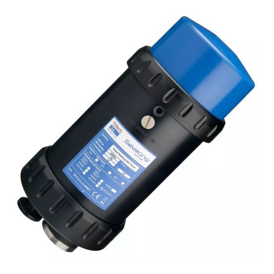
- Page 1 SeaKing Profiling Sonar SeaKing Profiling Sonar Product Manual 0374-SOM-00002, Issue: 04 0374-SOM-00002, Issue: 04 © Tritech International Ltd.
- Page 2 SeaKing Profiling Sonar © Tritech International Ltd The copyright in this document is the property of Tritech International Ltd. The document is supplied by Tritech International Ltd on the understanding that it may not be copied, used, or disclosed to others except as authorised in writing by Tritech International Ltd.
-
Page 3: Table Of Contents
SeaKing Profiling Sonar Table of Contents Help & Support .................... 5 Warning Symbols ..................6 1. Introduction ....................7 2. Specification .................... 8 2.1. Dimensions ................... 8 2.2. Acoustic ..................8 2.3. Physical ..................9 2.4. Electrical and Communication ............9 3. - Page 4 SeaKing Profiling Sonar A. ARCNET Termination ................54 B. SeaKing Sonar & Profiler Connector Options ........55 Glossary ..................... 56 0374-SOM-00002, Issue: 04 © Tritech International Ltd.
-
Page 5: Help & Support
SeaKing Profiling Sonar Help & Support First please read this manual thoroughly (particularly the Troubleshooting section, if present). If a warranty is applicable, further details can be found in the Warranty Statement, 0080-STF-00139, available upon request. Tritech International Ltd can be contacted as follows:... -
Page 6: Warning Symbols
SeaKing Profiling Sonar Warning Symbols Throughout this manual the following symbols may be used where applicable to denote any particular hazards or areas which should be given special attention: Note This symbol highlights anything which would be of particular interest to the reader or provides extra information outside of the current topic. -
Page 7: Introduction
SeaKing Profiling Sonar 1. Introduction A SeaKing Profiler System is made up from the Profiler, the Tritech International Ltd Seanet Pro control and display software and either a Surface Control Unit (SCU) or SeaHub. This manual deals with the Profiler and any specific aspects of Seanet Pro that are necessary to get a system working. -
Page 8: Specification
SeaKing Profiling Sonar 2. Specification 2.1. Dimensions Ø110 Not to scale, dimensions in mm. 2.2. Acoustic Property High frequency Low frequency Operating frequency 1.1MHz 600kHz Beamwidth 1° conical 2° conical Maximum range Pulse length 20 - 200μs Minimum range 0.3m Scan resolutions 0.45°, 0.9°, 1.35°... -
Page 9: Physical
Specification SeaKing Profiling Sonar 2.3. Physical Physical Weight in air 3.5kg (aluminium) Weight in water 1.7kg (aluminium) Materials Boot: Acetal copolymer Body tube: Anodised aluminium alloy (6Al4V Titanium optional) Depth rating 4000m Temperatures Operating: -10 to 35°C Storage: -20 to 50°C 2.4. -
Page 10: Installation
SeaKing Profiling Sonar 3. Installation 3.1. General Overview The SeaKing heads are supplied with a waterblock fitted to the device and as standard a proprietary connector usually referred to as the "Tritech 6- Way Connector". Other connectors are available and various lengths of test cable can be supplied with the connector. -
Page 11: Seaking Communication Configuration
Installation SeaKing Profiling Sonar over the head to protect from impact damage but this must not overlap the transducer area or it may have an effect on the profiler image. Caution It is important that no clamping force is applied to the boot. -
Page 12: Subsea Sensor Electrical Installation
Installation SeaKing Profiling Sonar pair cable. It is possible to interface the ARCNET to wide band multiplexer systems - contact Tritech International Ltd for details. Note For an ARCNET connection termination resistors need to be fitted at each end of the umbilical. Refer to Appendix A, ARCNET... -
Page 13: Waterblock Pin-Out Diagram
Installation SeaKing Profiling Sonar 3.3.4. Waterblock Pin-out Diagram MAIN port AUX port Cable colour RS232 TX RS232 RX Yellow ARCNET A ARCNET A RS485 A RS485 A RS232 Rx RS232 TX Blue ARCNET B ARCNET B Tritech Waterblock RS485 B... -
Page 14: Using Two Profilers With Rs232 Or Rs485
Installation SeaKing Profiling Sonar Note If using the dual Profilers with a Tritech International Ltd SeaHub or SCUv5 it is possible to link pin 5 at the surface and use standard cables instead. Refer to the SeaHub or SCU manual for further details. -
Page 15: Operation
SeaKing Profiling Sonar 4. Operation 4.1. Basic Principles On completion of installation of the Profiler(s) on a vehicle, they can be tested in air by powering up the system and observing that the red LED illuminates as the head scans through the ahead direction. - Page 16 Operation SeaKing Profiling Sonar The main areas of the display are: 1. Display Header This part of the screen is used for system/software identification. 2. Menu Bar This is where system set-up functions can be accessed. Where a menu item is relevant to a particular task it will be referenced in this manual, otherwise a full description of each menu is available in the Seanet Pro online help.
-
Page 17: Profiler Settings
Operation SeaKing Profiling Sonar 4.2.2. Profiler Settings The Profiler head controls are displayed on the Sonar Settings bar. When a RAT is used or screen cursor is moved over the Sonar Settings bar, a pop- up control panel will appear which will display the remaining controls. These mimic the positions of the rotary controls (C1 to C5) and function buttons (F1 to F7) on the RAT. - Page 18 Operation SeaKing Profiling Sonar button to switch focus between the display windows. The optional RAT controller will switch its control to the display that has the focus. Note: clicking on a display with the mouse pointer will also switch focus to that display.
-
Page 19: Seanet Setup
Operation SeaKing Profiling Sonar 4.2.3. Seanet Setup To set up the Seanet Pro system for use with a SeaKing Profiler the following basic procedure should be followed (these points are expanded below): 1. Connect the Profiler to the computer via a SeaHub or directly into the SCU (external power to the head is required at this point). - Page 20 Operation SeaKing Profiling Sonar Figure 4.1. Channel Setup Dialog Once the COM port is correctly configured the Profiler should connect and start communicating with the surface controller, the status indicator LEDs on the front of the SCU or SeaHub should show that communication is taking place.
-
Page 21: Re-Programming Nodes
Operation SeaKing Profiling Sonar This will bring up a setup dialog which will allow the communication protocols for the different ports to be altered. Make sure that the ports match the settings used by the profiler and click OK. After a short delay the node table will be rebuilt. - Page 22 Operation SeaKing Profiling Sonar To Re-Program a Node 1. Open the Seanet Setup program and wait for a few seconds for the nodes to build. 2. Click on the Action column for the node that has Status of Update and then select Program.
- Page 23 Operation SeaKing Profiling Sonar 5. Wait until the download has completed and until the table has been rebuilt. The node status should change from Update to OK to indicate that the download has been completed. To Change a Node Number...
-
Page 24: Changing System Settings
Operation SeaKing Profiling Sonar 2. Click on the Action column for the node that requires its node number to be changed (node 21 in this case) and then select Change Node. 3. Enter the new node number to be programmed into the device. - Page 25 Operation SeaKing Profiling Sonar This is a SeaHub although SCUv5 settings are very similar. Note that Rates is greyed out and Baud cannot be accessed - this is changed from the COM Setup dialog as described later. This is the dialog box for a PCI AIF card equipped SCUv4 or for an PCI AIF card installed into a PC.
-
Page 26: Application Tools
Operation SeaKing Profiling Sonar • USB is the USB to serial converter • SeaHubxxx SeaHub port (‘A’..’D’, ’Main’, ’Aux’) • Generic Legacy COM Port and other 4. Then, click on the Settings ellipsis button (…) to open the Communication Settings panel to configure the port. The COM Port number and Baud rate can also be viewed or changed. - Page 27 Operation SeaKing Profiling Sonar Cursor The Cursor tool reports the X and Y position from the origin. The units of the reported figure are the same units as used throughout the Profiler application and are set using the Setup tool.
- Page 28 Operation SeaKing Profiling Sonar Zoom Zoom mode draws a zoom box on the display which can be positioned by the mouse pointer. Zoom Setup sets the size and magnification factor of zoom box. The Size shows the screen zoomed area as a percentage of the Zoom display window.
- Page 29 Operation SeaKing Profiling Sonar Display Grid Display the cross-hair grid. Labels Range labels on or off. Dot Size The size of the profile points. Tick Size The size of the grid cross-hairs. Head Size Size of the profile head indicators (Red for master and Green for Slave).
- Page 30 Operation SeaKing Profiling Sonar Lockout Sets a minimum range (in metres) from the transducer where echoes will be ignored. Effectively, this is a blanking radius on the Profiler Display area. There are separate Lockouts for Low and High Frequency channels.
- Page 31 Operation SeaKing Profiling Sonar level for the receive echoes (0-80dB) and should nominally be set to around 50. Reducing the Threshold value will result in back scatter and generally lower amplitude echo returns being detected and used in the plotting of the profile.
- Page 32 Operation SeaKing Profiling Sonar Pipe Setup Using serial TSS Pipetracker data input, this will configure a simulated pipe overlay for display on the Profiler plot. Offset (X,Y) Position the pipe with reference to the 0,0 origin on the Profiler Cartesian display (in metres).
- Page 33 Operation SeaKing Profiling Sonar NMEA TRO $-TRO,x.xx,a,y.yy,b*kk<CR><LF> NMEA TRH $-TRH,x.xx,a,y.yy,b,z.zz,c*kk<CR><LF> CDL1 H123.4P+123.45R+123.45T00.0D00000.0B00.0FR<CR><LF> H0750P-0019R-0022<CR><LF> Digilog H0750P-0019R-0022E<CR><LF> CDL MicroTilt P+12.34R+12.34<CR><LF> A serial port can be configured by selecting Com Setup from the Utilities menu, and then enabling an Attitude Sensor device (it may be necessary to select one from the New menu if it is not already listed).
- Page 34 Operation SeaKing Profiling Sonar Roll Setup In this dialog, there are several settings to be configured: Centre of Rotation X, 'Y' Sets the X,Y co-ordinate position offset which is relative to the Profiler display datum (= origin 0,0). Rotation Offset R...
- Page 35 Operation SeaKing Profiling Sonar Enabled Check-box to display the Overlay on the Profiler display. Enable Mouse Move Should be ticked to drag/move the position of the Overlay on the display using the left mouse button. It is recommended this be disabled during operations to prevent inadvertent movement through accidental mouse operations.
-
Page 36: Software Features
SeaKing Profiling Sonar 5. Software Features 5.1. Mean Altitude 5.1.1. Overview From Seanet Pro V2 onwards, there is facility to calculate a mean altitude value from the Profiler data points of a single or dual head scan. Data points from the Master, Slave or both heads in a dual head pair can be applied in the mean altitude calculation. - Page 37 Software Features SeaKing Profiling Sonar dialog. To open the Mean Altitude dialog right-click on the Profiler application main screen and select Mean Altitude. Note If the option does not appear in the popup menu list then it may be hidden – contact Tritech International Ltd for details on how to enable this option.
-
Page 38: Mean Altitude Operation
Software Features SeaKing Profiling Sonar 5.1.2. Mean Altitude Operation The mean altitude calculation will function with a single or dual head Profiler system. Note If a 4-head profiler system is employed and displayed as Quad Profiler, the 1st pair will normally be used for the mean altitude calculation. - Page 39 Software Features SeaKing Profiling Sonar in a pair can be applied, otherwise there is option to select a Master or Slave head for single head operation or None to switch off mean altitude calculation. There is also option to apply a Global mean altitude value which has been calculated by another Profiler head set (e.g., from another set of heads in a 2nd...
- Page 40 Software Features SeaKing Profiling Sonar Example 5.1. Global Mean Altitude with Two Profiler Applications • The Top Profiler form has been configured to calculate a Mean Altitude value and then use this value as the Global Mean Altitude (= ‘Make Global’) which other forms can pick up and apply.
-
Page 41: Gate Alarm
Software Features SeaKing Profiling Sonar Example 5.2. Global Mean Altitude with Profiler and Sonar Applications • The Bottom Profiler form is calculating Mean Altitude which has been made Global. • The Top Imaging (Sonar) form will automatically pick up the Global Mean Altitude. -
Page 42: Configuring The Alarm
Software Features SeaKing Profiling Sonar A remote alarm message can also be configured for transmittal via a serial port. This is configured using the Seanet RemV4 utility. 5.2.2. Configuring the Alarm Note To configure the alarm, it is necessary to first configure an overlay - refer to the section called “Overlay”... - Page 43 Software Features SeaKing Profiling Sonar Note Seanet Pro must be running at the time that Seanet RemV4 is configured. Data is passed from Seanet Pro to inform the RemV4 utility which devices are operating. To configure the remote alarm a channel will need to be set for the output message, the channels are set using the Remote Channel Setup dialog which is accessed from the Settings menu (in RemV4).
-
Page 44: Remote Alarm String Format
Software Features SeaKing Profiling Sonar This will launch the output configuration dialog named Slot 2, Output 1: Within this dialog it will be necessary to select the Channel which was previously configured and then click on Gate Alarm On to enable the alarm to be transmitted over the COM port (when the alarm is activated in Seanet Pro an ASCII string will be sent out). -
Page 45: Synchronisation
Software Features SeaKing Profiling Sonar <CR> = Carriage Return and <LF> = Line Feed 5.3. Synchronisation If running a dual head system it is important to set the synchronisation of the Profilers correctly. The synchronisation is set using the Setup dialog which is accessed by right-clicking on the main window and selecting Setup and then Sync Mode. -
Page 46: Offsets
Software Features SeaKing Profiling Sonar scans do not overlap then Scan Sync can be chosen instead to speed up the profiling. 5.4. Offsets Offsets are applied in the Profiler application by selecting Position from the Application Tools menu (or by right-clicking on Profiler main screen). - Page 47 Software Features SeaKing Profiling Sonar Note For the purposes of a mean altitude calculation, only the R and Y offsets are relevant. 0374-SOM-00002, Issue: 04 © Tritech International Ltd.
-
Page 48: Maintenance
SeaKing Profiling Sonar 6. Maintenance 6.1. After using the profiler Make sure that after using the profiler head that it is washed down with fresh water and check the unit for any signs of obvious damage. Pay particular attention to the transducer head and free any organic matter which has become trapped. -
Page 49: Disassembly Of The Seaking Unit
Maintenance SeaKing Profiling Sonar Exploded view diagram Item Part Description Number S01037 Body O-ring S01204 Connector ASSY Endcap S00009 0161-16 O-ring S01252 Endcap puller S01299 M5x25 Endcap puller screw S00987 Waterblock S01182 Pressurised ASSY blanking cap 10 S01038 Retaining O-... - Page 50 Maintenance SeaKing Profiling Sonar If wishing to dismantle the unit, for any reason, due care and attention should be taken to prevent damage or injury. Important The steps outlined here will expose sensitive electronic equipment and so appropriate steps should be taken to prevent any static discharge occurring which may harm the equipment.
-
Page 51: Reassembly Of The Seaking Unit
Maintenance SeaKing Profiling Sonar 9. Remove the last PCB and then unscrew the four guide posts from the connector endcap Once fully disassembled, inspect the various o-ring seals and sealing surfaces for signs of damage and corrosion. Pitting and corrosion within an o-ring sealing area can cause a unit to lose integrity and lead to water ingress and significant damage. - Page 52 Maintenance SeaKing Profiling Sonar • A 5.5mm spanner, or nut spinner • A small nose flush plier, or M2.5 spanner Procedure 1. Carefully clean all parts and check for damage. 2. Inspect o-ring seals and replace if necessary. 3. Screw in the four guide posts onto the connector endcap 4.
-
Page 53: Troubleshooting
SeaKing Profiling Sonar 7. Troubleshooting Continuous Status Timeout 20 message This indicates that there is no communication with the device flagged – in this case the Node number of the device is 20 (= Master Profiler). Check the power and communications links to the sonar head for continuity and for correct polarity, voltage and ensure that the power supply can provide sufficient current to power all devices. - Page 54 SeaKing Profiling Sonar Appendix A. ARCNET Termination Depending on the cable length the ARCNET communication link requires a termination resistor to be installed at each end of the umbilical cable. Normally this is supplied fitted within the ARCNET cable DA-15 or within the SCU/SeaHub at the surface and is left for the user to fit at the sub-sea end in a convenient junction box or by use of a special waterblock.
- Page 55 SeaKing Profiling Sonar Appendix B. SeaKing Sonar & Profiler Connector Options The SeaKing sonar can be fitted at the factory with a variety of connector options to allow quick and easy integration into an existing network or sonars or other ROV equipment. For more details contact Tritech International Ltd.
- Page 56 SeaKing Profiling Sonar Glossary Originally "Acoustic Interface" but also used to refer to "ARCNET Interface" in which case it can refer to either the interface port on a SeaHub or SCU or to the expansion card available for installation into a computer.
- Page 57 Glossary SeaKing Profiling Sonar SeaHub An alternative to using a Seanet SCU, this device connects to a laptop or PC via USB interface, essentially this takes the signal from the sonar (in RS232, RS485 or ARCNET) and converts it into a signal suitable for the USB port of the computer.
Need help?
Do you have a question about the SeaKing Profiling Sonar and is the answer not in the manual?
Questions and answers