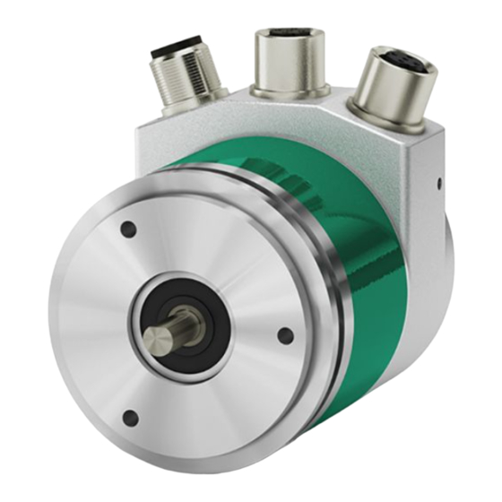
Lika EM58 MT User Manual

Lika EM58 MT User Manual

27-bit multiturn/18-bit singleturn/30-bit multiturn encoder for standard purposes/high precision demands/high end applications m12 connectors
Hide thumbs Also See for EM58 MT:
Table of Contents

Advertisement

Quick Links

Smart encoders & actuators
EM58 MT
HS58 MT
HM58 MT
• EM58 27-bit multiturn encoder for standard purposes
• HS58 18-bit singleturn encoder for high precision demands
• HM58 30-bit multiturn encoder for high end applications
• M12 connectors
• Complies with the "Modbus over TCP/IP" protocol
Suitable for the following models:
EM58, EM58S MT
EMC58, EMC59, EMC60 MT
HS58, HS58S MT
HSC58, HSC59, HSC60 MT
HM58, HM58S MT
HMC58, HMC59, HMC60 MT
Lika Electronic

User's guide

Tel. +39 0445 806600
MODBUS TCP/IP
General Contents
Preliminary information
1 - Safety summary
2 - Identification
3 - Mounting instructions
4 - Electrical connections
5 - Quick reference
6 - MODBUS® TCP/IP interface
info@lika.biz
17
19
20
25
33
34
www.lika.biz
8

Advertisement

Table of Contents
loading

Summary of Contents for Lika EM58 MT

  • Page 1: User's Guide

    User's guide Smart encoders & actuators EM58 MT HS58 MT HM58 MT MODBUS TCP/IP • EM58 27-bit multiturn encoder for standard purposes • HS58 18-bit singleturn encoder for high precision demands • HM58 30-bit multiturn encoder for high end applications •...
  • Page 2 Tous droits réservés. This document and information contained herein are the property of Lika Electronic s.r.l. and shall not be reproduced in whole or in part without prior written approval of Lika Electronic s.r.l. Translation, reproduction and total or partial modification (photostat copies, film and microfilm included and any other means) are forbidden without written authorisation of Lika Electronic s.r.l.
  • Page 3: Table Of Contents

    General contents User's guide......................................1 General contents.....................................3 Subject index.....................................6 Typographic and iconographic conventions........................7 Preliminary information................................8 Glossary of MODBUS TCP/IP terms............................9 List of abbreviations...................................15 References......................................16 1 Safety summary..................................17 1.1 Safety......................................17 1.2 Electrical safety..................................17 1.3 Mechanical safety................................18 2 Identification....................................19 3 Mounting instructions................................20 3.1 Solid shaft encoders................................20 3.1.1.
  • Page 4 06 Write Single Register............................43 16 Write Multiple Registers...........................45 6.6 Encoder states..................................50 WAIT_PROCESS................................50 ERROR....................................50 PROCESS_ACTIVE................................50 EXCEPTION..................................50 7 Programming parameters..............................51 7.1 Parameters available................................51 7.1.1 Holding Register parameters..........................51 Watchdog timeout [82]..............................52 Current position [95-96]............................52 Speed value [97-98]..............................52 Status word [99-100]..............................53 Counts per revolution [101-102].........................53 Total Resolution [103-104].............................54...
  • Page 5 7.2 Exception response and codes............................71 8 Integrated web server................................74 8.1 Integrated web server – Preliminary information....................74 8.2 Web server Home page..............................75 8.3 Encoder position and speed............................76 8.3.1 Specific notes on using Internet Explorer......................77 8.4 Encoder information (MODBUS registers)........................78 8.5 Setting the Preset value..............................79 8.6 Setting the registers................................81 8.7 Firmware upgrade................................85 8.8 Network configuration..............................91...
  • Page 6: Subject Index

    Subject index PCB Hardware Version [131-132]......66 Perform counting preset..........61 Alarm..................69 Preset value [105-106]..........56 Alarm registers [121-122]..........64 Preset value error.............65 PROCESS_ACTIVE.............50 Code sequence............59, 69 Control Word [111-112]..........60 Restore default parameters.........60 Counts per revolution [101-102]......53 Counts per revolution error.........65 Current position [1-2]............68 Save parameters...............60 Current position [95-96]..........52 Scaling function............58, 69...
  • Page 7: Typographic And Iconographic Conventions

    Typographic and iconographic conventions In this guide, to make it easier to understand and read the text the following typographic and iconographic conventions are used: parameters and objects both of the device and the interface are coloured in GREEN; • alarms are coloured in RED;...
  • Page 8: Preliminary Information

    Preliminary information This guide is designed to provide the most complete information the operator needs to correctly and safely install and operate the following rotary encoders equipped with MODBUS TCP/IP interface: EMxxx13/16384MT-xx (multiturn encoder, resolution 13 +14 bits) HSxxx18/MT-xx (singleturn encoder, resolution 18 bits) HMxxx16/16384MT-xx (multiturn encoder, resolution 16 +14 bits) For technical specifications please refer to the product datasheet.
  • Page 9: Glossary Of Modbus Tcp/Ip Terms

    Glossary of MODBUS TCP/IP terms MODBUS TCP/IP, like many other networking systems, has a set of unique terminology. Table below contains a few of the technical terms used in this guide to describe the MODBUS TCP/IP interface. They are listed in alphabetical order. Application Data Unit, it is the data frame of the MODBUS protocol.
  • Page 10 Valid codes are in the range of 1 ... 255 decimal (the range 128 – 255 is reserved and used for exception responses). Function code "0" is not valid. Lika encoders only implement public function codes. Refer to page 38.
  • Page 11 IEEE 1588 This standard defines a protocol enabling synchronisation of clocks in distributed networked devices (e.g. connected via Ethernet). Input register In the MODBUS data model, an Input register is the input data. An Input register has a 16-bit quantity, is provided by an I/O system, and allows read-only access.
  • Page 12 message to follow. Unit Identifier: 1 byte set by the Client and echoed by • the Server for identification of a remote slave connected on a serial line or on other buses. Refer to page 35. Media Access Control One of the sub-layers of the Data Link Layer that controls who gets access to the medium to send a message.
  • Page 13 packet inside the same node. Port numbers are divided between well-known port numbers (0-1023), registered user port numbers (1024-49151) and private-dynamic port numbers (49152-65535). For TCP, port number 0 is reserved and cannot be used. Ports allow TCP/IP to multiplex and demultiplex a sequence if IP datagrams that need to go to many different (simultaneous) application processes.
  • Page 14 and passengers. The data is actually transported by protocols. This is comparable to cars and commercial vehicles transporting passengers and goods on the highway. Tasks handled by the basic Transmission Control Protocol (TCP) and Internet Protocol (IP) (abbreviated to TCP/IP): 1.
  • Page 15: List Of Abbreviations

    List of abbreviations Table below contains a list of abbreviations (in alphabetical order) which may be used in this guide to describe the MODBUS TCP/IP interface. Application Data Unit HDLC High level Data Link Control Human Machine Interface Input/Output IETF Internet Engineering Task Force Internet Protocol Media Access Control...
  • Page 16: References

    References MODBUS Application Protocol Specification, Version V1.1b3 MODBUS messaging on TCP/IP implementation guide, Version V1.0b RFC 791, Internet Protocol, Sep81 DARPA RFC 1122 Requirements for Internet Hosts -- Communication Layers IEC 61918 Industrial communication networks – Installation of communication networks in industrial premises IEC 61784-5-13 Industrial communication networks –...
  • Page 17: Safety Summary

     failure to comply with these precautions or with specific warnings elsewhere in this manual violates safety standards of design, manufacture, and intended use of the equipment;  Lika Electronic assumes no liability for the customer's failure to comply with these requirements. 1.2 Electrical safety ...
  • Page 18: Mechanical Safety

    EM58 – HS58 - HM58 MODBUS TCP/IP 1.3 Mechanical safety  Install the device following strictly the information in the “3 - Mounting instructions” section on page 20;  mechanical installation has to be carried out with stationary mechanical parts; ...
  • Page 19: Identification

    MAC address printed on the label applied to its body. Information is listed in the delivery document too. Please always quote the order code, the serial number and the MAC address when reaching Lika Electronic for purchasing spare parts or needing assistance. For any information on the technical characteristics of the product refer to the technical catalogue.
  • Page 20: Mounting Instructions

    EM58 – HS58 - HM58 MODBUS TCP/IP Mounting instructions WARNING Installation and maintenance operations have to be carried out by qualified personnel only, with power supply disconnected and mechanical parts absolutely in stop. For any information on the mechanical data and the electrical characteristics of the encoder please refer to the technical catalogue.
  • Page 21: Installation Using Fixing Clamps (Code Lkm-386)

    EM58 – HS58 - HM58 MODBUS TCP/IP 3.1.2 Installation using fixing clamps (code LKM-386) a [mm] b [mm] c [mm] d [mm] EM58, HS58, HM58 50 F7 EM58S, HS58S, HM58S 36 H7 3.1.3 Installation using a mounting bell (code PF4256) NOTE In order to guarantee reliability over time of the encoder mechanical parts, we recommend a flexible coupling to be installed between the encoder and the...
  • Page 22: Hollow Shaft Encoders

    • insert the anti-rotation pin 1 into the slot on the flange of the encoder; this secures it in place by grub screw 2, preset at Lika; • fix the collar 3 to the encoder shaft (apply some threadlocker to the screw 3).
  • Page 23: Emc59, Hsc59, Hmc59

    EM58 – HS58 - HM58 MODBUS TCP/IP 3.2.2 EMC59, HSC59, HMC59 • Remove the anti-rotation pin 1 (see the Figure in the previous page); • mount the encoder on the motor shaft using the reducing sleeve 8 (if supplied). Avoid forcing the encoder shaft; •...
  • Page 24: Emc60, Hsc60, Hmc60

    EM58 – HS58 - HM58 MODBUS TCP/IP 3.2.3 EMC60, HSC60, HMC60 • Remove the anti-rotation pin 1 (see the Figure on page 22); • fix the tempered pin 6 to the rear of the motor; • mount the encoder on the motor shaft using the reducing sleeve 8 (if supplied).
  • Page 25: Electrical Connections

    EM58 – HS58 - HM58 MODBUS TCP/IP Electrical connections WARNING Power supply must be turned off before performing any electrical connection! Figure 1 - Connectors and diagnostic LEDs 4.1 M12 connectors The connection cap is fitted with three M12 connectors with pin-out in compliance with the Ethernet standard.
  • Page 26: P1 Port 1 And P2 Port 2 Connectors (Figure 1)

    To minimize noise connect properly the shield and/or the connector housing and/or the frame to ground. Connect properly the cable shield to ground on user's side. Lika's EC- pre-assembled cables are fitted with shield connection to the connector ring nut in order to allow grounding through the body of the MAN EM58_HS58_HM58 MT E 1.1.odt...
  • Page 27: Connection Of The Shield

    EM58 – HS58 - HM58 MODBUS TCP/IP device. Lika's E- connectors have a plastic gland, thus grounding is not possible. If metal connectors are used, connect the cable shield properly as recommended by the manufacturer. Anyway make sure that ground is not affected by noise. It is recommended to provide the ground connection as close as possible to the device.
  • Page 28: Setting The Ip Address And The Network Configuration Parameters

    EM58 – HS58 - HM58 MODBUS TCP/IP The IP address must be assigned by the user to each interface of the unit to be connected in the network, the default IP address assigned by Lika Electronic is 192.168.1.10, while the default subnet mask is 255.255.255.0.
  • Page 29: Line Termination

    EM58 – HS58 - HM58 MODBUS TCP/IP 4.6 Line Termination MODBUS TCP/IP network needs no line termination because the line is terminated automatically; in fact every Slave is able to detect the presence of the downstream Slaves. 4.7 Diagnostic LEDs (Figure 1) Five LEDs located in the cap of the encoder (see the Figure 1) are meant to show visually the operating or fault status of the encoder and the MODBUS interface.
  • Page 30: Dip A: Resetting The Network Configuration Parameters To The Factory Values

    EM58 – HS58 - HM58 MODBUS TCP/IP The encoder power supply is switched OFF. The encoder power supply is switched ON. Description MS Module It shows the state of the MODBUS TCP/IP device. Status LED (green / red) The device power supply is switched OFF. The device is in normal operational state.
  • Page 31 EM58 – HS58 - HM58 MODBUS TCP/IP connection cap. For any information on removing the connection cap please refer to the following “4.9 Connection cap (Figure 2)” section. If for any reason you must restore the factory values (default values) of the network configuration parameters (IP address, Subnet mask, DHCP), access the DIP A dip-switch proceeding as follows: WARNING...
  • Page 32: Connection Cap (Figure 2)

    EM58 – HS58 - HM58 MODBUS TCP/IP 4.9 Connection cap (Figure 2) WARNING Do not remove or mount the connection cap with power supply switched ON. Damage may be caused to internal components. The DIP A DIP switch meant to reset the network configuration parameters to the factory values (default values) is located inside the connection cap (see on page 30).
  • Page 33: Quick Reference

    EM58 – HS58 - HM58 MODBUS TCP/IP Quick reference 5.1 Getting started The following instructions are provided to allow the operator to set up the device for standard operation in a quick and safe mode. Mechanically install the device; • execute the electrical connections;...
  • Page 34: Modbus® Tcp/Ip Interface

    EM58 – HS58 - HM58 MODBUS TCP/IP MODBUS® TCP/IP interface Lika MODBUS TCP/IP encoders are Slave (Server) devices and implement the MODBUS application protocol (level 7 of OSI model) and the “MODBUS messaging on TCP/IP” protocol (Ethernet: levels 1 & 2 of OSI model; TCP/IP: levels 3 &...
  • Page 35: General Modbus Frame Description

    EM58 – HS58 - HM58 MODBUS TCP/IP it supports standard Ethernet and does not require dedicated Masters or • chipsets; standard PC Ethernet cards and PCs can be used to communicate in any Ethernet network; it does not require any configuration file; •...
  • Page 36 EM58 – HS58 - HM58 MODBUS TCP/IP protocol). Essentially, the MODBUS TCP/IP message is simply a MODBUS communication encapsulated in an Ethernet TCP/IP wrapper. In practice, MODBUS TCP embeds a standard MODBUS data frame into a TCP frame, without the MODBUS RTU address and checksum, as shown in the following diagram.
  • Page 37: Modbus Pdus

    EM58 – HS58 - HM58 MODBUS TCP/IP FUNCTION CODE: the function code indicates to the Server what kind • of action to perform. The function code is followed by a DATA field that contains request and response parameters. All MODBUS request and responses are designed in such a way that the recipient can verify that a message is finished.
  • Page 38: Function Codes

    EM58 – HS58 - HM58 MODBUS TCP/IP The MODBUS Response PDU is defined as {function_code, response_data}, where: function_code = MODBUS function code [1 byte]; response_data = this field is function code dependent and usually contains information such as variable references, variable counts, data offsets, sub- function, etc.
  • Page 39: Implemented Function Codes

    EM58 – HS58 - HM58 MODBUS TCP/IP 6.5.1 Implemented function codes Lika MODBUS TCP/IP encoders only implement public function codes, they are described hereafter. 03 Read Holding Registers FC = 03 (0003 hex) ro This function code is used to READ the contents of a contiguous block of Holding Registers (4X Reference Addresses) in a remote device;...
  • Page 40 EM58 – HS58 - HM58 MODBUS TCP/IP Preset value [105-106] Here is an example of a request to read the registers (address 104-105). Request Response Field name (Hex) Field name (Hex) Function Function Starting address Hi Byte count Starting address Lo Register 105 value Hi No.
  • Page 41: Read Input Registers

    EM58 – HS58 - HM58 MODBUS TCP/IP [04] = number of bytes (2 bytes for each register) [00][00] = value of register 105, 00 00 hex = 0 dec [05][DC] = value of register 106, 05 DC hex = 1500 dec 04 Read Input Registers FC = 04 (0004 hex) This function code is used to READ from 1 to 125 contiguous Input Registers (3X...
  • Page 42 EM58 – HS58 - HM58 MODBUS TCP/IP Current position [1-2] Here is an example of a request to read the registers (address 0-1). Request Response Field name (Hex) Field name (Hex) Function Function Starting address Hi Byte count Starting address Lo Register 1 value Hi Quantity of Input Reg.
  • Page 43: Write Single Register

    EM58 – HS58 - HM58 MODBUS TCP/IP [2F][F0] = value of register 2, 2F F0 hex = 12272 dec 06 Write Single Register FC = 06 (0006 hex) This function code is used to WRITE a single Holding Register (4X Reference Addresses) in a remote device.
  • Page 44 EM58 – HS58 - HM58 MODBUS TCP/IP Watchdog timeout [82] Here is an example of a request to write in the register (address 81): you want to enable the Watchdog function and set the timeout to 10 ms. Request Response Field name (Hex) Field name...
  • Page 45: Write Multiple Registers

    EM58 – HS58 - HM58 MODBUS TCP/IP [00][0A] = value set in the register 16 Write Multiple Registers FC = 16 (0010 hex) This function code is used to WRITE a block of contiguous Holding Registers (4X Reference Addresses, 1 to 123 registers) in a remote device. The values to be written are specified in the request data field.
  • Page 46 EM58 – HS58 - HM58 MODBUS TCP/IP Here is an example of a request to write the value 00 00 08 00 hex (=2048 dec) Counts per revolution [101-102] next to the registers (address 100-101) and Total Resolution [103- the value 00 80 00 00 hex (=8388608 dec) next to the 104] registers (address 102-103).
  • Page 47 EM58 – HS58 - HM58 MODBUS TCP/IP [00][00] = Protocol Identifier [00][0F] = Length [00] = Unit Identifier [10] = 16 Write Multiple Registers function code (Counts per revolution [101-102] [00][64] = starting address registers, address 100-101) [00][04] = number of requested registers [08] = number of bytes (2 bytes for each register) [00][00] = value to be set in the register 101, 00 00 hex [08][00] = value to be set in the register 102, 08 00 hex (00 00 08 00 hex = 2048...
  • Page 48 EM58 – HS58 - HM58 MODBUS TCP/IP Operating parameters [109- Here is an example of a request to write in the 110] registers (address 108-109): we need to set the scaling function (bit 0 Scaling function = 1) and the count up information with clockwise rotation of the encoder shaft (bit 1 Code sequence = 0).
  • Page 49 EM58 – HS58 - HM58 MODBUS TCP/IP [04] = number of bytes (2 bytes for each register) [00][00] = value to be set in the register 109, 00 00 hex [00][01] = value to be set in the register 110, 00 01 hex The MODBUS TCP/IP ADU needed to send back a response following the request to set the scaling function (bit 0 Scaling function = 1) and the count up information with clockwise rotation of the encoder shaft (bit 1 Code sequence...
  • Page 50: Encoder States

    EM58 – HS58 - HM58 MODBUS TCP/IP 6.6 Encoder states The table below describes the states the encoder can enter during operation in the MODBUS TCP/IP network. Encoder state Description WAIT_PROCESS Waiting for MODBUS requests. The encoder shifts PROCESS_ACTIVE state as soon as a MODBUS request is received.
  • Page 51: Programming Parameters

    EM58 – HS58 - HM58 MODBUS TCP/IP Programming parameters 7.1 Parameters available Hereafter the parameters available for the MODBUS encoders are listed and described as follows: Parameter name [Register number] [register address, data type, attribute]  The register number and address are expressed in decimal notation. ...
  • Page 52: Watchdog Timeout [82]

    EM58 – HS58 - HM58 MODBUS TCP/IP Watchdog timeout [82] [81, Unsigned16, rw] For safety reasons, while the encoder is on, a continuous data exchange between the Master and the Slave has to be planned in order to be sure that the communication is always active;...
  • Page 53: Status Word [99-100]

    EM58 – HS58 - HM58 MODBUS TCP/IP Status word [99-100] [98-99, Unsigned16, ro] Status word [5-6] input registers are also available as holding registers at the address 98-99 and accessible by using the 03 Read Holding Registers function code. For any information refer to page 68. Counts per revolution [101-102] [100-101, Unsigned32, rw] WARNING...
  • Page 54: Total Resolution [103-104]

    EM58 – HS58 - HM58 MODBUS TCP/IP Counts per revolution Furthermore, after having set a new value next to the [101-102] registers, make sure that also the following condition is met: Number of physical Total Resolution [103-104] revolutions (see Number of ≤...
  • Page 55 EM58 – HS58 - HM58 MODBUS TCP/IP These registers are intended to set a custom number of distinguishable steps over the whole measuring range (overall resolution of the encoder). The total Counts per revolution resolution of the encoder results from the product of [101-102] by the required number of revolutions.
  • Page 56: Preset Value [105-106]

    EM58 – HS58 - HM58 MODBUS TCP/IP and perform the preset operation (bit 11 Perform counting preset in the Control Word [111-112] registers = 1). EXAMPLE We install the HM5816/16384MT multiturn encoder. Its physical resolution is as follows (see the order code): Singleturn resolution [113-114] ...
  • Page 57 EM58 – HS58 - HM58 MODBUS TCP/IP position of the encoder in the moment when the Perform counting preset Control Word [111-112] command available in the registers is sent. We suggest activating the preset value when the encoder is in stop. Default = 0 (min.
  • Page 58: Speed Format [107-108]

    EM58 – HS58 - HM58 MODBUS TCP/IP than or equal to the “Total hardware resolution” - 1, i.e. (Singleturn  resolution [113-114] Number of revolutions [115-116]) - 1.  If the Scaling function is enabled (the bit 0 in the Operating parameters [109-110] Preset value [105-106]...
  • Page 59: Code Sequence

    EM58 – HS58 - HM58 MODBUS TCP/IP Resolution [103-104] registers in compliance with the following relation: Transmitted position = Counts per revolution [101-102] * Real position ≤ Total Resolution [103-104] Singleturn resolution [113-114] NOTE To know whether the Scaling function is currently enabled, you can read the bit 0 Scaling function of the Status word [5-6]...
  • Page 60: Control Word

    This function allows the operator to restore all parameters to default values (default values are set at the factory by Lika Electronic engineers to allow the operator to run the device for standard operation in a safe mode). This function...
  • Page 61: Perform Counting Preset

    EM58 – HS58 - HM58 MODBUS TCP/IP must be switched back to logic level low (“0”) to make the function available again. The complete list of machine data and relevant default parameters preset by Lika Electronic engineers is available on page 100. WARNING...
  • Page 62: Singleturn Resolution [113-114]

    EM58 – HS58 - HM58 MODBUS TCP/IP Singleturn resolution [113-114] [112-113, Unsigned32, ro] WARNING These registers are active only if the bit 0 Scaling function in the Operating parameters [109-110] registers is set to “=0”; otherwise they are ignored and (Counts per revolution [101-102] the system uses the custom values Total Resolution...
  • Page 63: Supported Alarms [117-118]

    EM58 – HS58 - HM58 MODBUS TCP/IP Supported alarms [117-118] [116-117, Unsigned16, ro] Function bit = 0 bit = 1 0 … 11 not used Machine data not valid Alarm not supported Alarm supported Setting data not valid Alarm not supported Alarm supported Flash memory error Alarm not supported Alarm supported 15 …...
  • Page 64: Alarm Registers [121-122]

    EM58 – HS58 - HM58 MODBUS TCP/IP Alarm registers [121-122] [120-121, Unsigned16, ro] Function bit = 0 bit = 1 0 … 11 not used Machine data not valid Alarm not active Alarm active Setting data not valid Alarm not active Alarm active Flash memory error Alarm not active...
  • Page 65: Warnings Register [123-124]

    EM58 – HS58 - HM58 MODBUS TCP/IP Warnings register [123-124] [122-123, Unsigned16, ro] This variable is meant to show the warnings currently active in the device. No warnings are supported in this encoder. Wrong parameters list [125-126] [124-125, Unsigned16, ro] Machine data not valid The operator has entered invalid data and the alarm...
  • Page 66: Offset Value [127-128]

    EM58 – HS58 - HM58 MODBUS TCP/IP Bytes 1 … 3 Not used. Offset value [127-128] [126-127, Signed32, ro] As soon as you send the Perform counting preset command (see the bit 11 in Control Word [111-112] registers), the current position of the encoder is saved in these registers.
  • Page 67 EM58 – HS58 - HM58 MODBUS TCP/IP For example, the value 0001 0001 hex in hexadecimal notation corresponds to the binary representation 0000 0000 0000 0001 0000 0000 0000 0001 and has to be interpreted as: hardware version 1.1. MAN EM58_HS58_HM58 MT E 1.1.odt Programming parameters 67 of 104...
  • Page 68: Input Register Parameters

    EM58 – HS58 - HM58 MODBUS TCP/IP 7.1.2 Input Register parameters Input Registers are 3X Reference Registers and accessible for reading only; to read the value set in an input register parameter use the 04 Read Input Registers function code (reading of multiple input registers); for any further information on the implemented function codes refer to the “6.5.1 Implemented function codes“...
  • Page 69: Scaling Function

    EM58 – HS58 - HM58 MODBUS TCP/IP Byte 0 Scaling function bit 0 It shows whether the scaling function (see the bit 0 Scaling function of the Operating parameters [109-110] registers) is currently disabled or enabled. If the value is “=0” the scaling function is disabled (i.e. the system uses the physical values -Singleturn resolution [113-114]...
  • Page 70 EM58 – HS58 - HM58 MODBUS TCP/IP Bytes 2 and 3 Not used. NOTE Status word [5-6] input registers are also available as holding registers at the address 98-99 and accessible by using the 03 Read Holding Registers function code. For any information refer to page 53. MAN EM58_HS58_HM58 MT E 1.1.odt Programming parameters 70 of 104...
  • Page 71: Exception Response And Codes

    EM58 – HS58 - HM58 MODBUS TCP/IP 7.2 Exception response and codes When a Client device sends a request to a Server device it expects a normal response. One of four possible events can occur from the Master's query. If the Server device receives the request without a communication error •...
  • Page 72 EM58 – HS58 - HM58 MODBUS TCP/IP MODBUS Exception codes Code Name Meaning ILLEGAL FUNCTION The function code received in the query is not an allowable action for the server. This may be because the function code is only applicable to newer devices, and was not implemented in the unit selected.
  • Page 73 EM58 – HS58 - HM58 MODBUS TCP/IP processing long–duration program command. The client should retransmit the message later when the server is free. MEMORY PARITY ERROR Specialized use in conjunction with function codes 20 and 21 and reference type 6, to indicate that the extended file area failed to pass a consistency check.
  • Page 74: Integrated Web Server

    Integrated web server 8.1 Integrated web server – Preliminary information MODBUS TCP/IP encoders from Lika Electronic integrate a web server. This web- based user interface is designed to offer helpful functions and deliver complete information on the device that can be accessed through the Internet.
  • Page 75: Web Server Home Page

    1. type the IP address of the encoder you want to connect to (in the example: 192.168.1.10, this is the default IP address set at Lika, see on page 28) in the address bar of your web browser and confirm by pressing ENTER;...
  • Page 76: Encoder Position And Speed

    EM58 – HS58 - HM58 MODBUS TCP/IP Some commands are available in the menu bar of the Home page. Press on the Lika logo to enter Lika's web site (www.lika.biz). Press the Documentation command to enter the MODBUS TCP/IP encoder...
  • Page 77: Specific Notes On Using Internet Explorer

    EM58 – HS58 - HM58 MODBUS TCP/IP Speed The current encoder speed is expressed according to the setting next the format [107-108] registers on page 58 (steps per second or revolutions per Speed value [3-4] minute). For any information refer to the registers on page NOTE The current encoder position and speed values are real-time processed and...
  • Page 78: Encoder Information (Modbus Registers)

    EM58 – HS58 - HM58 MODBUS TCP/IP 8.4 Encoder information (MODBUS registers) Press the Encoder information command in the left navigation bar of the Web server Home page to enter the Encoder Information page. In this page the complete list of the available MODBUS registers is displayed. Figure 6 - Encoder Information page The registers listed under the Input registers section are process data and read- only access values.
  • Page 79: Setting The Preset Value

    EM58 – HS58 - HM58 MODBUS TCP/IP NOTE The registers in the Encoder Information page cannot be changed even though they are read-write access registers. To change the set values please enter the Set Registers page (see on page 81). Press the Homepage command to move back to the Web server Home page.
  • Page 80 EM58 – HS58 - HM58 MODBUS TCP/IP Figure 8 - Preset operation aborted If you confirm the procedure, the Set Encoder Preset page will appear on the screen: Figure 9 - Set Encoder Preset page Preset value [105- The Preset value that is currently set in the encoder (see the 106] registers on page 56) will be displayed in the READ box.
  • Page 81: Setting The Registers

    EM58 – HS58 - HM58 MODBUS TCP/IP NOTE Preset value Please note that the Preset value is now saved temporarily in the [105-106] Preset registers. To save permanently the set Preset value in the value [105-106] registers, please press the Save Preset button. Should the power supply be turned off without saving data, the Preset value that has not been saved on the Flash EEProm will be lost! For more information refer to the Save parameters command in the...
  • Page 82 EM58 – HS58 - HM58 MODBUS TCP/IP Figure 10 - Entering the Set Encoder Registers page Press the OK button to proceed, otherwise press the EXIT button to exit the procedure. The Set Registers cancelled! message will appear on the screen. Press the OK button to move back to the Web server Home page.
  • Page 83 EM58 – HS58 - HM58 MODBUS TCP/IP If you confirm the procedure, the Set Encoder Registers page will appear on the screen: Figure 12 - Set Encoder Registers page The values that are currently set in the encoder are displayed in the READ box. To change any value enter a suitable value in the WRITE box next to the desired parameter and then press the button between the boxes to confirm.
  • Page 84 Press the Load Default Param. button to restore all parameters to default values. Default values are set at the factory by Lika Electronic engineers to allow the operator to run the device for standard operation in a safe mode. This function can be useful, for instance, to restore the factory values in case the encoder is set incorrectly and you are not able to resume the proper operation.
  • Page 85: Firmware Upgrade

    The firmware upgrading program consists of a single file having .BIN extension. It is released by Lika Electronic Technical Assistance & After Sale Service. If the latest firmware version is already installed in the unit, you do not need to proceed with any new firmware installation.
  • Page 86 EM58 – HS58 - HM58 MODBUS TCP/IP a web browser (Internet Explorer, Mozilla Firefox, Google Chrome, Opera, • …) is installed in the PC or device used for connection; you have the SW_ETH_revX_Y.exe executable file; • you have the .BIN file for firmware upgrade. •...
  • Page 87 5. In the Password text box type the password LIKA (all uppercase letters) and then press the Send Request button. Figure 15 - Firmware Upgrade page MAN EM58_HS58_HM58 MT E 1.1.odt...
  • Page 88 OPEN command the OPEN dialog box appears on the screen: open the folder where the firmware upgrading .BIN file released by Lika Electronic is located, select the file and confirm. Hx in the file name shows the hardware version of the PCB; Sx shows the software version of the firmware upgrading file.
  • Page 89 EM58 – HS58 - HM58 MODBUS TCP/IP WARNING Please pay attention to install the BIN file that perfectly matches the series of the encoder to be updated. EM58_HMS_MT_Hx_Sx.bin for EM/HS/HM MODBUS/TCP encoders Figure 17 - Selecting the firmware upgrade .BIN file 13.
  • Page 90 EM58 – HS58 - HM58 MODBUS TCP/IP 15. A download progress bar as well as additional information are shown in the page while upgrading the firmware. Figure 18 - Updating the firmware 16. As soon as the operation is carried out successfully, the FILE SENT CORRECTLY message appears on the screen.
  • Page 91: Network Configuration

    EM58 – HS58 - HM58 MODBUS TCP/IP 17. Now you are required to turn the encoder power supply off and then on. Close the program. 18. Turn the encoder power supply off and then on to complete the operation. NOTE While downloading the firmware upgrading program, unexpected conditions may arise which could lead to a failure of the installation process.
  • Page 92 EM58 – HS58 - HM58 MODBUS TCP/IP Figure 20 - Entering the Network Configuration page Press the OK button to proceed: the Network Configuration page will appear on the screen. Figure 21 - Network Configuration page MAN EM58_HS58_HM58 MT E 1.1.odt Integrated web server 92 of 104...
  • Page 93 EM58 – HS58 - HM58 MODBUS TCP/IP WARNING Only competent technicians, who are properly trained, have adequate experience and are familiar with computer architecture, network design and operating systems should configure the network communication parameters. The inappropriate setting of the network parameters results in an incorrect operation of the system.
  • Page 94 EM58 – HS58 - HM58 MODBUS TCP/IP NOTE If for any reason you must restore the factory values (default values) of the network configuration parameters you must access the DIP A dip-switch located inside the connection cap. For complete information please refer to the “4.8 DIP A: Resetting the network configuration parameters to the factory values”...
  • Page 95: Programming Examples

    EM58 – HS58 - HM58 MODBUS TCP/IP Programming examples Hereafter are some examples of both reading and writing parameters. All values are expressed in hexadecimal notation. For any information on the MODBUS TCP/IP ADU (MBAP Header + PDU) refer to the “6.3 MODBUS on TCP/IP Application Data Unit”...
  • Page 96: Using The 04 Read Input Registers Function Code

    EM58 – HS58 - HM58 MODBUS TCP/IP 9.2 Using the 04 Read Input Registers function code EXAMPLE 1 Current position [1-2] Request to read the registers (address 0-1). MBAP Header + Request PDU (in hexadecimal notation) [00][01][00][00][00][06][00][04][00][00][00][02] where: [00][01] = Transaction Identifier [00][00] = Protocol Identifier [00][06] = Length [00] = Unit Identifier...
  • Page 97: Using The 06 Write Single Register Function Code

    EM58 – HS58 - HM58 MODBUS TCP/IP 9.3 Using the 06 Write Single Register function code EXAMPLE 1 Watchdog timeout [82] Request to write in the register (address 81): you want to enable the Watchdog function and set the timeout to 10 ms. MBAP Header + Request PDU (in hexadecimal notation) [00][01][00][00][00][06][00][06][00][51][00][0A] where:...
  • Page 98: Using The 16 Write Multiple Registers Function Code

    EM58 – HS58 - HM58 MODBUS TCP/IP 9.4 Using the 16 Write Multiple Registers function code EXAMPLE 1 Counts per Request to write the value 00 00 08 00 hex (=2048 dec) next to the revolution [101-102] registers (address 100-101) and the value 00 80 00 00 Total Resolution [103-104] hex (= 8388608 dec) next to the registers (address...
  • Page 99 EM58 – HS58 - HM58 MODBUS TCP/IP will be programmed to have a 2048-count-per-revolution single-turn resolution and 4096 revolutions (8388608/2048). EXAMPLE 2 Operating parameters [109-110] Request to write in the registers (address 108-109): we need to set the scaling function (bit 0 Scaling function = 1) and the count up information with clockwise rotation of the encoder shaft (bit 1 Code sequence = 0).
  • Page 100: Default Parameters List

    EM58 – HS58 - HM58 MODBUS TCP/IP 10 Default parameters list Default values are expressed in decimal notation, unless otherwise indicated. Parameters list Default values Watchdog timeout [82] 8192 for EM58 series Counts per revolution [101-102] 262144 for HS58 series 65536 for HM58 series 134217728...
  • Page 101 This page intentionally left blank...
  • Page 102 This page intentionally left blank...
  • Page 103 This page intentionally left blank...
  • Page 104 Ce dispositif doit être alimenté par un circuit de Classe 2 ou à très basse tension ou bien en appliquant une tension maxi de 30Vcc. Voir le code de commande pour la tension d'alimentation. Lika Electronic Via S. Lorenzo, 25 • 36010 Carrè (VI) •...

This manual is also suitable for:

Hs58 mtHm58 mtEm58s mtEmc58 mtEmc59 mtEmc60 mt

Table of Contents