
Subscribe to Our Youtube Channel
Related Manuals for Magnetic Autocontrol MPT-132


Summary of Contents for Magnetic Autocontrol MPT-132
- Page 1 Operating instructions Full Height Turnstile MPT-132 Doc-ID: 5817,5811EN Version: 02...
- Page 2 Translation of the original operating instructions MAGNETIC Autocontrol GmbH Grienmatt 20 79650 Schopfheim Germany Tel.: +49 (0) 7622 695 5 Fax.: +49 (0)7622 695 602 E-Mail: info@ac-magnetic.com Internet: www.ac-magnetic.com 5817,5811EN / Version 02...
-
Page 3: Table Of Contents
Full Height Turnstile MPT-132 Contents Contents General ..................7 Information about the operating instructions ....7 Pictogram explanation ........... 8 Limitation of liability ............9 Copyright protection ............9 Scope of delivery ............10 Spare parts ..............10 Warranty conditions ............. 10 Disclaimer .............. - Page 4 Full Height Turnstile MPT-132 Contents Assemble the full height turnstile MPT-132 ....28 5.4.1 Mounting full height turnstile on the foundation ......... 29 5.4.2 Mounting the support beam ......30 5.4.3 Removing lock unit (optional) ...... 32 5.4.4 Dismounting locking discs ......33 5.4.5...
- Page 5 Full Height Turnstile MPT-132 Contents 10.2 Error message – motor control unit MMC-120 .... 59 10.3 Downloading new software to logic controller MBC-110 ......... 61 11 Spare parts ................62 12 Decommissioning, disassembly and disposal ....62 13 EC-Declaration of Conformity ..........63 14 Appendix ................
- Page 6 Full Height Turnstile MPT-132 5817,5811EN / Version 02...
-
Page 7: General
General Information about the operating instructions These operating instructions provide important information on how to deal with the MAGNETIC full height turnstile MPT-132. Prereq- uisite for safe working is the observance of all specified safety notes and instructions. In addition, the local accident prevention regulations valid at the barrier's area of application and general safety regulations have to be complied with. -
Page 8: Pictogram Explanation
Full Height Turnstile MPT-132 General Pictogram explanation Warning notes Warning notes are characterized by pictograms in these operating instructions. The warning notes are preceded by signal words ex- pressing the scale of the hazard. It is absolutely essential to observe the notes and to proceed with caution in order to prevent accidents as well as bodily injuries and property damage. -
Page 9: Limitation Of Liability
Full Height Turnstile MPT-132 General Limitation of liability All specifications and notes in these operating instructions were compiled in consideration to the valid standards and regulations, state-of-the-art technology and our long-standing knowledge and experience. The manufacturer is not liable for damage caused by: ... -
Page 10: Scope Of Delivery
Full Height Turnstile MPT-132 General Scope of delivery The scope of delivery comprises: 1 x Cage halves, steel or stainless steel 1 x Center column 3 x 120° 1 x Support beam with drive unit, MBC control unit,... -
Page 11: Disclaimer
Full Height Turnstile MPT-132 General Disclaimer MAGNETIC expressly disclaims all implied and statutory warran- ties, including but not limited to, the implied warranties of mer- chantability and fitness for a particular purpose with respect to the product and the statutory warranty of non-infringement of third par- ty rights set forth in section 2312(3) of the uniform commercial code. -
Page 12: Safety
Full Height Turnstile MPT-132 Safety Safety Intended use The MAGNETIC pedestrian barrier MPT is intended solely for con- trolling pedestrians in areas with authorized access. The full height turnstile is usually integrated into the fence and gate complex. The pedestrian barrier is intended for passage of persons who can pass the pedestrian barrier safely, quickly and without help. -
Page 13: Operating Personnel
Full Height Turnstile MPT-132 Safety Operating personnel 2.3.1 Requirements WARNING Risk of injury in case of inadequate qualification! Improper handling can lead to considerable physi- cal injuries and property damage. – Have any activities only carried out by the indi- viduals assigned for that purpose. -
Page 14: Operator's Responsibility
Full Height Turnstile MPT-132 Safety Operator's Responsibility The operator must comply with the statutory obligations regarding work safety. In addition to the work safety notes in these operating instructions, the safety, accident prevention and environmental provisions appli- cable for the area the pedestrian barrier is used in must be com- plied with. -
Page 15: Personal Protective Equipment
2.6.1 Danger pictograms on the pedestrian barrier MPT-132 The relevant dangerous areas on the barriers can be identified by the following pictograms: Electric voltage... -
Page 16: Hazard Warnings And Occupational Safety
Full Height Turnstile MPT-132 Safety 2.6.2 Hazard warnings and occupational safety For your own safety and for the protections of the barrier modules, the following information must be observed and complied with: Electric voltage DANGER Mortal danger by electric voltage! Touching live parts can be lethal. - Page 17 Full Height Turnstile MPT-132 Safety Improper transport WARNING Danger by falling down or tilting of a pedestrian barrier! The weight of the pedestrian barrier or its heavy components can cause serious physical injury and crushing! – Have all transport work performed by trained personnel.
- Page 18 Full Height Turnstile MPT-132 Safety Inadmissible operation WARNING Risk of injury at inadmissible operation! An inadmissible operation can cause death or seri- ous injuries. – Before operating the barriers check all electrical and mechanical functions. Sharp edges and spiky corners...
-
Page 19: Technical Data
Full Height Turnstile MPT-132 Technical data Technical data Electrical connection Designation Unit Value Supply voltage V AC / Hz 230 / 50 Current consumption: Pedestrain barrier open/close Current consumption: Pedestrain barrier in motion Starting current (approx. 30ms) Power consumption: Rest position... -
Page 20: Design And Function
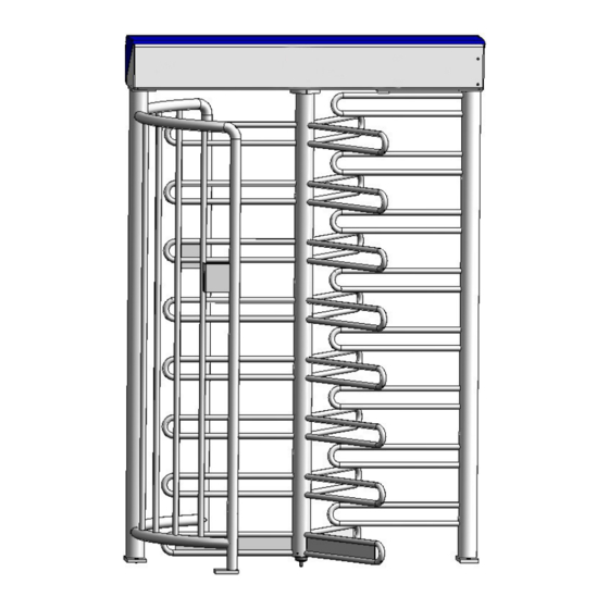
Full Height Turnstile MPT-132 Design and function Design and function Design Fig. 1: Design of components Cage halves Center column Synthetic bearing Lock comb Support beam with drive unit and drive flange Service doorr Top cover 5817,5811EN / Version 02... -
Page 21: Versions
Full Height Turnstile MPT-132 Design and function Versions Fig. 2: "Entry from left" version Fig. 3: "Entry from right" version Function The pedestrian barrier MPT is intended for the controlling of pedes- trians in outdoor areas with a relatively high security requirement. -
Page 22: Assembly And Installation
Full Height Turnstile MPT-132 Assembly and installation Assembly and installation Safety General WARNING Danger by inappropriate installation! Inappropriate installation can cause severe injuries! – Only qualified personnel, authorise and briefed by the contracting partner may carry out all in- stallation and assembly. -
Page 23: Requirements For Assembly
Full Height Turnstile MPT-132 Assembly and installation Heavy weight WARNING Risk of injury when lifting heavy objects alone! The weight of heavy objects can seriously injure a person! – The pedestrian barrier or its heavy components must be carried and lifted from the pallet by a minimum of two people. -
Page 24: Foundation And Empty Conduits
Full Height Turnstile MPT-132 Assembly and installation Foundation and empty conduits NOTE! To provide a trouble-free operation use separate conduits for data cables and mains cables. The functional safety of the pedestrian barrier hinges on the accuracy of the foundation. -
Page 25: Foundation Plan
Full Height Turnstile MPT-132 Assembly and installation 5.3.1 Foundation plan 1800 1424 Fig. 4: Foundation plan Passage direction Empty conduits Bearing Drilling jig Foundation anchor (F) with M10 internal thread, 16 mm bore hole, drilling depth: 90 mm Have cables overlapping for approx. 5 m of the conduits ... - Page 26 Full Height Turnstile MPT-132 Assembly and installation Fig. 5: Foundation plan and layout for empty conduits Smooth trowel finish foundation, level and horizontal Lay data cables and power cables in separate empty conduits. Leave empty conduits approx. 50 mm above the foundation.
-
Page 27: Base Frame
Full Height Turnstile MPT-132 Assembly and installation 5.3.2 Base frame A base frame must be used to facilitate assembly on stone pave- ments or similar surfaces. Left version Right version Fig. 6: Base frame Possible cable penetration from the foundation into the... -
Page 28: Assemble The Full Height Turnstile Mpt-132
Full Height Turnstile MPT-132 Assembly and installation Assemble the full height turnstile MPT-132 Fig. 7: Entry from left version Fig. 9: Assemble full height turnstile Cage halves Center column Synthetic bearing Lock comb Support beam with drive unit and drive flange Service doorr Fig. -
Page 29: Mounting Full Height Turnstile On The Foundation
Full Height Turnstile MPT-132 Assembly and installation NOTE! Before starting assembly, establish whether the cage half is to be right or left entry. See Fig. 9. If code card reader, buttons or columns are pre- mounted on the cage half, they are important for setup. -
Page 30: Mounting The Support Beam
Full Height Turnstile MPT-132 Assembly and installation Pull the power cable and any control cables completely through the tube of the lock comb (Fig. 9, Pos. 1) and/or the cage half (Pos. 2). Fig. 12: Setting up cage halves and lock comb Grease the supplied M 10 screws. - Page 31 Full Height Turnstile MPT-132 Assembly and installation Fig. 14: Mounting the support beam Position the support beam (Fig. 9, Pos. 3) using the hoist onto the lock comb and cage half. WARNING! Risk of injury from a falling support beam! Immediately secure and tightenthe support beam using the 4 M 12 x 35 countersunk screws supplied.
-
Page 32: Removing Lock Unit (Optional)
Full Height Turnstile MPT-132 Assembly and installation 5.4.3 Removing lock unit (optional) NOTE! The drive unit has various loosely fastened ele- ments for transportation purposes. The center column has to be partially removed be- fore it can be mounted. Fig. 17: Loosen hexagon socket screws on top housing with drive unit Loosen the 4 hexagon socket screws on the lock unit. -
Page 33: Dismounting Locking Discs
Full Height Turnstile MPT-132 Assembly and installation 5.4.4 Dismounting locking discs NOTE! Complete the following steps, always turning the drive flange in a clockwise direction (viewed from below). NOTE! The drive unit has various loosely fastened ele- ments for transportation purposes. - Page 34 Full Height Turnstile MPT-132 Assembly and installation Fig. 21: Remove the fixing screw Remove the 1st fixing screw. Turn the drive flange for 180°. Remove the 2nd fixing screw. Fig. 22: Left locking disc Note! The illustration of the locking disc does not correspond to the original.
-
Page 35: Dismounting Centering Bolts
Full Height Turnstile MPT-132 Assembly and installation Fig. 24: Dismounting locking discs 5.4.5 Dismounting centering bolts Fig. 25: Centering bolts Dismount the 4 centering bolts. Turn the flange so that the two bore holes for the fastening screws on the center column can be accessed from the side. -
Page 36: Mounting The Floor Bearing, Mounting The Center Column On The Drive Flange
Full Height Turnstile MPT-132 Assembly and installation 5.4.6 Mounting the floor bearing, mounting the center column on the drive flange Fig. 26: Floor bearing (synthetic bearing) Screw Spring washer Disc Sleeve Bearing pin Disc Bearing Mount the synthetic bearings on the finished floor. - Page 37 Full Height Turnstile MPT-132 Assembly and installation Fig. 28: Mounting center column onto the drive flange Fasten the center column using the 4 M 16 screws supplied from the top to the drive flange. Screw in the fastening screw with spring washer for the center column as shown.
-
Page 38: Mounting Centering Bolts, Locking Discs And Lock Unit
Full Height Turnstile MPT-132 Assembly and installation 5.4.7 Mounting centering bolts, locking discs and lock unit Mount the centering bolts, the lock disc and lock unit (optional) in the reverse order to dismounting. See Page 32 etc., Chapter 0, 5.4.4 and 5.4.5. -
Page 39: Setting The Blocked Position (Home Position)
Full Height Turnstile MPT-132 Assembly and installation 5.4.9 Setting the blocked position (home position) Figure 31 Setting the full height turnstile to the "blocked" position Lock comb Center column: blocked position Cage halves Fig. 32: Cam plate with proximity switch Set the center column with lock comb to the "blocked"... -
Page 40: Electrical Connection
Full Height Turnstile MPT-132 Electrical connection Electrical connection Safety General WARNING Danger by inappropriate installation! Inappropriate installation can causes serious inju- ries or death. – Only qualified personnel, authorized by the op- erator and instructed appropriately, may carry out electrical installation tasks. -
Page 41: Power Supply Connection
Full Height Turnstile MPT-132 Electrical connection Power supply connection 6.2.1 Connecting the power supply Fig. 33: Power supply Terminals L, N, PE 2-pole mains switch Connect the power cable only to the correct terminals L, N, PE (1). The 2-pole main switch (2) de-energizes the entire unit. -
Page 42: Inputs And Outputs, Customer
Full Height Turnstile MPT-132 Electrical connection 6.2.2 Inputs and outputs, customer The following connections are available for control and feedback on customer’s side: 6 Digital inputs to control the pedestrian barrier. Red LEDs indicate the switching state of the inputs ... -
Page 43: Connection Diagram
Full Height Turnstile MPT-132 Electrical connection Connection diagram Fig. 35: MBC-110, customer's connection (5527,5113) 5817,5811EN / Version 02... -
Page 44: Inputs X2
Full Height Turnstile MPT-132 Electrical connection Inputs X2 Input Function Description IN1+ Emergency (ASB signal for The function of input 1 cannot be changed, as the input servo-controller) hardware is connected to the ASB input of the motor out- IN1- put stage. -
Page 45: Relay Outputs X1
Full Height Turnstile MPT-132 Electrical connection Relay outputs X1 Isolated relay contacts, wired in groups Switched voltage 5 - 24V Switched current 10 mA - 1 A Relay output Function Description Global error / When certain errors occur, a permanent signal is deliv-... -
Page 46: Configuring The Pedestrian Barrier
Full Height Turnstile MPT-132 Configuring the pedestrian barrier Configuring the pedestrian barrier Safety General WARNING Risk of injury due to inappropriate configuration! Incorrect configuration can cause injury. – Only sufficiently qualified personnel authorized and instructed by the user are allowed for the configuration of the pedestrian barrier. -
Page 47: Dip Switch Block S1
Full Height Turnstile MPT-132 Configuring the pedestrian barrier 7.2.1 DIP switch block S1 DIP S1.x Function Description Pulse storage When pulse storage is deactivated, the barrier is cleared via a pulse to one of the two opening inputs. If further opening pulses are received while the barrier is still open, they are ig- nored. - Page 48 Full Height Turnstile MPT-132 Configuring the pedestrian barrier DIP S1.x Function Description Security Level The setting defines how the lock is to respond if there are several attempts to pass the barrier in the wrong direction. The "Security low" setting enables a complete passage in the locked direction in several steps.
- Page 49 Full Height Turnstile MPT-132 Configuring the pedestrian barrier Table 7: DIP switch block S1 5817,5811EN / Version 02...
-
Page 50: Dip Switch Block S2
Full Height Turnstile MPT-132 Configuring the pedestrian barrier 7.2.2 DIP switch block S2 DIP S2.x Function Description Heating active This DIP switch is used to specify whether or not the auxiliary heating should be activated. Options OFF: Auxiliary heating inactive ... -
Page 51: Start-Up And Operation
Full Height Turnstile MPT-132 Start-up and operation Start-up and operation Safety General WARNING Danger by inappropriate start-up and operation! Inappropriate start-up and operation can cause se- rious injuries or death. – Make sure that the top cover is correctly mount- ed before starting work. -
Page 52: Start-Up
Full Height Turnstile MPT-132 Start-up and operation Start-up The following inspections must be performed prior to initial start-up: Inspection prior to initial start-up Check power supply. Check wiring emergency input IN1. Refer to Page 43, Fig. 35. ... -
Page 53: Maintenance
Full Height Turnstile MPT-132 Maintenance Maintenance Safety General WARNING Danger by inappropriate maintenance! Inappropriate start-up and operation can cause se- vere injuries or death. – Only qualified personnel, authorized by the op- erator and instructed appropriately, may carry out maintenance tasks. -
Page 54: Cleaning
Full Height Turnstile MPT-132 Maintenance Personal protective equipment The following must be worn during maintenance work: Work clothes Protective gloves Safety shoes. Cleaning Aggressive cleaning aids and sub- NOTICE stances Unit damage possible! Aggressive cleaning agents and substances can damage or destroy electrical cables and compo- nents. -
Page 55: Maintenance Schedule
Full Height Turnstile MPT-132 Maintenance Maintenance schedule The following describes the maintenance work that is necessary for optimal, trouble-free operation. If increased wear of individual components or functional groups is revealed during regular inspections, the operator must reduce the required maintenance intervals on the basis of the actual signs of wear. -
Page 56: 10 Troubleshooting
Full Height Turnstile MPT-132 Troubleshooting 10 Troubleshooting NOTE! Additionally, dispose of the diagnostic program MBC Diag for further diagnostics. This program can be used to read all error states from the MBC-110 and the associated MMC-120. For further infor- mation contact your authorized dealer or MAGNET- IC directly. -
Page 57: Display Of The Error Codes At The Mbc-110
Full Height Turnstile MPT-132 Troubleshooting 10.1.1 Display of the error codes at the MBC-110 When the DIP switch S1.8 is set to OFF (factory setting), the dis- play indicates a message if an error occurs. See also Page 49, Ta- ble 7. -
Page 58: Error Message On The Mbc-110
Full Height Turnstile MPT-132 Troubleshooting 10.1.3 Error message on the MBC-110 Error mes- Error description Automatic reset sage Obstruction detection with runtime monitoring Emergency input is activated Reserved Reserved Wrong way Wrong way high security Vandalism detection Reserved 09 – 0F Reserved 11 –... -
Page 59: Error Message - Motor Control Unit Mmc-120
Full Height Turnstile MPT-132 Troubleshooting 10.2 Error message – motor control unit MMC-120 Fig. 38: LEDs on MMC-120 Red LED for error diagnosis Green LED for indication of the power supply state and the safety input state Description Possible cause /... - Page 60 Full Height Turnstile MPT-132 Troubleshooting Error message Description Possible cause Resolver error Plug not properly inserted, short circuit Motor phase error Motor cable not connected. Wiring defective CAN communication with MBC-110 inter- Lifeguarding CAN rupted. Short circuit to ground Short circuit between motor phase and...
-
Page 61: Downloading New Software To Logic Controller Mbc-110
Full Height Turnstile MPT-132 Troubleshooting 10.3 Downloading new software to logic controller MBC-110 NOTE! Before a download, the position of the DIP switch on the MBC-110 must be noted so that the unit can be restored to its previous operating state following the download. -
Page 62: 11 Spare Parts
Full Height Turnstile MPT-132 Spare parts 11 Spare parts WARNING Risk of injury by incorrect spare parts! Incorrect or defective spare parts can result in damage, malfunctions or total failure and also im- pair safety. – Use only the manufacturer's original spare parts. -
Page 64: 14 Appendix
Full Height Turnstile MPT-132 Appendix 14 Appendix 14.1 Electrical circuit diagram The electric circuit diagram is supplied as a separate document. 5817,5811EN / Version 02... -
Page 65: Index
Full Height Turnstile MPT-132 Index Index Error message – motor control unit MMC-120 ... 59 Assembly Centering bolts ..........38 Foundation ............ 24, 26 Dismount centering bolts ........ 35 Function .............. 21 Dismount locking discs ........33 Fix the center column to the floor bearing ..38 General .............. - Page 66 Full Height Turnstile MPT-132 Index Switching off ............52 Switching on ............52 Safety ..............12 Synthetic bearing ......... 20, 28 Assembly ............22 Configuration ..........46 Electrical connection ........40 Technical data ............ 19 Installation ............22 Top cover ............. 20, 28 Maintenance ...........
- Page 67 Full Height Turnstile MPT-132 5817,5811EN / Version 02...
- Page 68 MAGNETIC Autocontrol GmbH Grienmatt 20 79650 Schopfheim Germany Tel.: +49 7622 695 5 Fax: +49 7622 695 602 e-mail: info@ac-magnetic.com...
Need help?
Do you have a question about the MPT-132 and is the answer not in the manual?
Questions and answers