
Subscribe to Our Youtube Channel
Related Manuals for Magnetic Autocontrol MPT-333


Summary of Contents for Magnetic Autocontrol MPT-333
- Page 1 Operating Instructions Full Height Turnstile MPT-333 Doc.ID: 5817,0028EN Version 00...
- Page 2 MPT-333 MAGNETIC AUTOCONTROL GMBH Grienmatt 20 D-79650 Schopfheim Germany Phone +49 7622 695 5 Fax +49 7622 695 802 info@magnetic-germany.com www.magnetic-access.com...
-
Page 3: Table Of Contents
MPT-333 Contents Contents Notes on the document Purpose and contents of this operating instructions Read and store the operating instructions Non-compliance with the operating instructions Symbols and illustrations used in these operating instructions 1.4.1 Warning notes and notes Safety Intended use... - Page 4 Assembling and mounting the base frame 7.6.1 Assembling the base frame 7.6.2 Assembling the base frame Preliminary work for installation directly on the foundation Mounting the MPT-333 7.8.1 Assembling the locking comb and cage half 7.8.2 Mounting the support beam 7.8.3 Assembling the centre pillar 7.8.4...
- Page 5 MPT-333 Contents Electrical connection Safety during electrical connection Installing electrical protective devices Open and close cover or service door 8.3.1 Opening and closing the cover 8.3.2 Opening and closing the service door Connecting the mains cable Connecting customer control lines 8.5.1...
- Page 6 MPT-333 Disassembly and disposal 17.1 Safety during disassembly and disposal 17.2 Disassembly and disposal of the system EU-Declaration of Conformity Index...
-
Page 7: Notes On The Document
IMPORTANT! For the parameterisation of the MGC control unit see separate document "Description of MGC control unit for MPT-333 Full Height Turnstile (Doc.ID: 5817,0027)". Read and store the operating instructions Pre-requisite for safe working is the observance of all specified safety notes, warning notes and instructions. -
Page 8: Non-Compliance With The Operating Instructions
MPT-333 Notes on the document Non-compliance with the operating instructions Magnetic declines all liability for personal injury and material damage caused by not observing the operating instructions. This applies in particular to damage caused by: › Non-intended use › Use of non-qualified personnel ›... - Page 9 MPT-333 Notes on the document CAUTION The signal word CAUTION points to a potentially dangerous situ- ation, which can lead to minor injuries if it is not avoided. NOTICE The signal word NOTICE points to a potentially harmful situation, which leads to property damage if it is not avoided.
-
Page 10: Safety
Safety Safety Intended use The Magnetic turnstile MPT-333 is only intended for access control of persons from a zone not controlled (ZNC) to a zone controlled (ZC). The turnstile is intended for passage of persons who can pass the turnstile safely, speedily and without any help. -
Page 11: Target Groups
MPT-333 Safety Target groups 2.3.1 Operator and his responsibilities The operator must comply with the statutory obligations regarding work safety. In addition to the safety instructions and warning notes in these operating in- structions, the valid safety, accident prevention and environmental protection regulations must be observed. -
Page 12: Personnel - Activities And Qualifications
MPT-333 Safety 2.3.2 Personnel - activities and qualifications Only authorised, trained and sufficiently qualified personnel may work on and with the product. The personnel must know and understand the operating in- structions and the required operating instructions. Designation Qualification ›... -
Page 13: Personal Protective Equipment
MPT-333 Safety Action Transport Technician Electrical spe- Operator equipment op- cialist erator Transporting – – Unpacking – Laying the foundation – – – Assembly – – Electrically connect – – Parameterise – – Commissioning – – Operating – Cleaning –... -
Page 14: Symbols On The Device
MPT-333 Safety Symbols on the device Warning of dangerous electrical voltage! The warning sign indicates hazardous areas with dangerous elec- trical voltage. Non-observance of the warning signs causes se- vere injuries or death. The work to be carried out may only be carried out by a qualified electrician or an electric safety expert. -
Page 15: To Protect The Environment
MPT-333 Safety To protect the environment Improper disposal! Improper disposal can lead to damage to the environment. › Dispose of product in accordance with local and national laws and regulations. › Sort resources and supply them to recycling. Emergency opening of the pedestrian gate... -
Page 16: Technical Data
MPT-333 Technical data Technical data Dimensions and design 1510 102.5 1424 1500 Fig. 1: Dimensions MPT-333 - front view (dimensions in mm), shown here version "entrance side left", lighting optional... - Page 17 MPT-333 Technical data Fig. 2: Dimensions MPT-333 - side view (dimensions in mm), lighting optional...
- Page 18 MPT-333 Technical data ∅ 16 ∅ 35 Fig. 3: Dimensions MPT-333 - view from below (dimensions in mm), lighting optional Designation Value Dimensions without attachments 1510 mm x 1288 mm x 2235 mm (width x depth x height) › Weight Turnstile without attachments: 325 kg ›...
-
Page 19: Electrical Connection
MPT-333 Technical data Electrical connection Designation Value 230 V AC / 50 Hz 120 V AC / 60 Hz Power supply 100 to 240 V AC ± 10 %, 50 to 60 Hz › › Max. current consumption In movement: 0.32 A In movement: 0.4 A... -
Page 20: Control Unit Mgc
MPT-333 Technical data Control unit MGC Designation Value Power supply 24 V DC Control unit max. 1 A max. 300 mA + current consumption of the differ- ent plug-in modules Power consumption max. 24 W: Max. 7.2 W + Power consumption of the individu-... -
Page 21: Design And Function
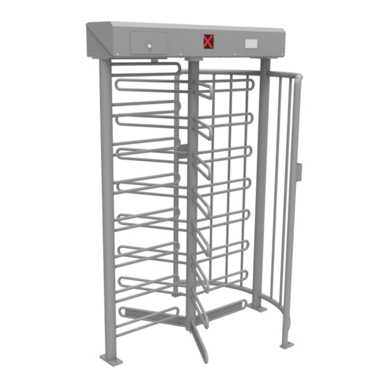
MPT-333 Design and function Design and function Design Fig. 4: Design "Full Height Turnstile MPT-333" Cage half Mounting bracket for optional attachment control devices Floor bearing Centre pillar Locking comb Support beam with drive unit and drive flange Cover Service door... -
Page 22: Function
MPT-333 Design and function Function The MPT turnstile is used to control pedestrians in outdoor areas with relative- ly high safety requirements. The turnstile can be operated either in one direc- tion or in both directions. Normally, the turnstile is closed. Only after authorisation by means of an exter- nal command unit, such as a card reader, will a passage be possible and the centre pillar can be rotated by 120°. -
Page 23: Versions And Definitions
MPT-333 Design and function Versions and definitions Left and right › Left: The passage is to the left of the locking comb. › Right: The passage is to the right of the locking comb. Entry and exit The service door or the cover of the support beam points into the zone con- trolled. - Page 24 MPT-333 Design and function Version "Entrance side left" Entry Exit Fig. 7: Version "Entrance side left" – view Fig. 8: Version "Entrance side left" – view from the zone not controlled (ZNC), from the zone controlled (ZC), the exit the entrance is to the left of the lock-...
-
Page 25: Receipt Of Goods, Transport And Storage
MPT-333 Receipt of goods, transport and storage Receipt of goods, transport and storage Goods receiving department Immediately check the delivery after receipt for completeness and transport damages. In the event of externally visible transport damage, proceed as follows: › Do not accept the delivery or only under reserve. -
Page 26: Transport
MPT-333 Receipt of goods, transport and storage WARNING Lifting of heavy loads! The weight of heavy objects can severely injure a person's back or supportive system. › Preferably transport the transported goods with suitable trans- port aids. › Alternatively, the transported goods can be carried by two per- sons. -
Page 27: Storage
MPT-333 Receipt of goods, transport and storage Storage Store packages or the product under the following conditions: › Store the delivery in its original packaging. Observe the symbols on the packaging. › Do not store outdoors. › Store dry and dust free. -
Page 28: Unpacking, Scope Of Delivery And Identification
MPT-333 Unpacking, scope of delivery and identification Unpacking, scope of delivery and identification Unpacking WARNING Lifting of heavy loads! The weight of heavy objects can severely injure a person's back or supportive system. › Preferably transport the transported goods with suitable trans- port aids. -
Page 29: Scope Of Delivery
MPT-333 Unpacking, scope of delivery and identification Scope of delivery The following components are supplied as standard for each MPT-333 turnstile: › Centre pillar › Cage half › Locking comb › Support beam with control unit, drive unit and drive flange and mounted cover ›... -
Page 30: Type Plate
The type plate is located under the cover to the right of the drive unit. MAGNETIC AUTOCONTROL GmbH D-79650 Schopfheim Ser.-Nr. Made in Germany Fig. 9: Type plate MPT-333 Product name Serial number Power supply Frequency Current consumption Power consumption IP rating Duty cycle for operating mode S1 "Continuous operation"... -
Page 31: Assembly
MPT-333 Assembly Assembly Safety during assembly Qualification of personnel › Technician › Electrical specialist ä Page 12, chapter 2.3.2. Personal protective equipment Wear the following personal protective equipment: › Work clothes › Protective gloves › Safety shoes › Protective helmet. -
Page 32: Assembly Options
MPT-333 Assembly WARNING Lifting of heavy loads! The weight of heavy objects can severely injure a person's back or supportive system! › Preferably transport the transported goods with suitable trans- port aids. › Alternatively, the transported goods can be carried by two per- sons. -
Page 33: Required Steps
Install and connect access-control devices. ä Page 69, chapter 8.6. Specifying the installation position The turnstile MPT-333 is available in the versions "Entrance side right" and "En- trance side left". ä Page 23, chapter 4.3. The layout of the components depends on the version ordered. The service... -
Page 34: Setting Up Foundation And Placing Empty Conduits
MPT-333 Assembly Setting up foundation and placing empty conduits 7.5.1 Requirements foundation The foundation must meet the following requirements: › Have sufficient load-carrying capacity › Concrete C20/25 or corresponding industrial floor › Attachment must be able to grip securely ›... -
Page 35: Setting Up Foundation And Placing Empty Conduits
MPT-333 Assembly 7.5.3 Setting up foundation and placing empty conduits Excavate the foundation hole according to the foundation and empty con- duit plan. Place empty conduits according to the foundation and empty conduit plan in the foundation hole. Close empty conduit to prevent water from entering. -
Page 36: Foundation And Empty Conduit Plan For Base Frame Fura T3
MPT-333 Assembly 7.5.4 Foundation and empty conduit plan for base frame FURA T3 1800 1612 1410 1257.5 1110 Fig. 10: Foundation and empty conduit plan for base frame FURA T3 – top view (dimensions in mm) Base frame FURA T3... - Page 37 MPT-333 Assembly Fig. 11: Foundation and empty conduit plan for base frame FURA T3 – side view (dimensions in mm) Finished paving such as interlocking stones or cobblestones, flush with the attach- ment plates Gravel and sand layer Base frame level and horizontal, fill any hollows under the base frame...
-
Page 38: Foundation And Empty Conduit Plan For Direct Mounting
MPT-333 Assembly 7.5.5 Foundation and empty conduit plan for direct mounting 1800 1424 Fig. 12: Foundation and empty conduit plan for direct mounting – top view (dimensions in mm) Foundation C35/45 XD3 XF2 with reinforcement, foundation depth: at least 800 mm,... - Page 39 MPT-333 Assembly Mag00897 Fig. 13: Foundation and empty conduit plan for direct mounting – side view (dimensions in mm) Foundation C35/45 XD3 XF2 with reinforcement, foundation depth: at least 800 mm, frost-proof Empty conduit: Lay empty conduits separately for mains cable and control lines. Al- low empty conduits to protrude approx.
-
Page 40: Assembling And Mounting The Base Frame
MPT-333 Assembly Assembling and mounting the base frame You need to install the pedestrian gate with a base frame on interlocking stone paving. Dimensions of foundation and base frame, position of foundation anchors, lev- elling screws and empty conduits: ä Page 36, Fig. 10. - Page 41 MPT-333 Assembly min. 5 m Fig. 15: Assembling the base frame FURA T3 Base frame FURA T3 Borehole Sleeve with inner thread M10 x 110 Washer Ø10.5 Screw M10 x 60 Line e.g. mains cable...
- Page 42 MPT-333 Assembly Assembling the base frame IMPORTANT! The injection mortar is not included in the scope of delivery. We recommend the injection mortar Hilti HIT-HY 200-A for the Hilti sleeves with inner thread HIS-RN. Follow the separate instruc- tions for the injection mortar and foundation anchors.
-
Page 43: Preliminary Work For Installation Directly On The Foundation
ä Page 43, chapter 7.8. Mounting the MPT-333 The mounting of the turnstile on a base frame and the mounting of the turn- stile directly on a foundation are identical in procedure. Only the attachment material is partly different. -
Page 44: Assembling The Locking Comb And Cage Half
MPT-333 Assembly 7.8.1 Assembling the locking comb and cage half Pull the mains cable and control lines through the support of the locking comb. Install the locking comb. Fig. 16: Installing the locking comb Locking comb Hexagon head screw M10 x 30 Washer Ø10.5... - Page 45 MPT-333 Assembly Install the cage half. Fig. 17: Installing the cage half Cage half Hexagon head screw M10 x 30 Washer Ø10.5...
-
Page 46: Mounting The Support Beam
MPT-333 Assembly 7.8.2 Mounting the support beam Loosen the screw of the cover. Dismount the protective earth conductor at the cover. Pull off the cover to the front and remove it. Place the support beam on the cage half and the locking comb by means of a lifting device. - Page 47 MPT-333 Assembly Fig. 18: Putting on the support beam and installing it. Support beam Countersunk screw Nut M12 Toothed disc 10.5 for grounding the support beam Hexagon head screw M10 x 20 for grounding the support beam Mains cable and control lines...
-
Page 48: Assembling The Centre Pillar
MPT-333 Assembly 7.8.3 Assembling the centre pillar Attach sleeve and washer with hexagon head screw. Slide the plastic bearing over the sleeve, washer and hexagon head screw. Fig. 19: Mount floor bearing (plastic bearing, sleeve, washer and hexagon head screw) - Page 49 MPT-333 Assembly Place the centre pillar on the floor bearing. Fix the centre pillar to the drive flange from above using the four screws supplied. Make sure that the centre pillar is correctly positioned in rela- tion to the locking unit.
- Page 50 MPT-333 Assembly Fig. 20: Assembling the centre pillar Floor bearing Threaded pin Centre pillar Flange Washer Hexagon head screw, flange connection, secure with threadlocker such as Loctite 241.
- Page 51 MPT-333 Assembly Correct positioning of the centre pillar IMPORTANT! Observe correct positioning. The countersink on the switching cam (item 1) must point forward into the zone controlled (ZC). The centre pillar must be mounted such that the bracket row (item 3), which is opposite to the countersink on the underside of the centre pillar flange (item 2), is in the locked position.
-
Page 52: Assembly Of An Optional Mounting Pillar For Access-Control Devices
MPT-333 Assembly 7.8.4 Assembly of an optional mounting pillar for access-control devices IMPORTANT! Magnetic offers the mounting pillar ASMP as attachment for the installation of access-control devices. Fig. 22: Optional mounting pillars... - Page 53 MPT-333 Assembly If the mounting pillar was ordered at the same time as the pedestrian gate, pull wires are drawn in at the factory for the lines of the mounting pillar. Additional steps for subsequent ordering of the mounting pillar...
- Page 54 MPT-333 Assembly Installing the mounting pillar Fig. 24: Mounting pillar and attachment material...
- Page 55 MPT-333 Assembly Mount the U-profile to the outer support of the cage half. Fig. 25: Mounting the U-profile U-profile Outer support cage half Washers ø8.4 Spring washer A8 Hexagon head screw M8 x 30...
- Page 56 MPT-333 Assembly Mount the lower holder. Fig. 26: Mounting the lower holder Spring washer A6 Screw M6 x 16...
- Page 57 MPT-333 Assembly Mount the attachment angle to the mounting pillar. Tighten nut by hand. Fig. 27: Mounting the attachment angle Screw DIN 7991 M8 x 25 Sleeve Attachment angles Washer PE ø8.4 Washer ø8.4 Spring washer A8 Nut M8...
- Page 58 MPT-333 Assembly Mount the attachment angle with mounting pillar to the U-profile. Fig. 28: Mounting the attachment angle Spring washer A6 Screw M6 x 16...
- Page 59 MPT-333 Assembly Align the mounting pillar by turning it. Fig. 29: Aligning the mounting pillar...
-
Page 60: Closing The Cover Of The Support Beam
MPT-333 Assembly Fix the mounting pillar to the lower holder. Fig. 30: Fixing the mounting pillar Nut M8 Spring washer A8 Washer ø8.4 Screw M8 x 25 Tighten the screw and nut on the upper attachment angle. 7.8.5 Closing the cover of the support beam When the installation work is completed or during extended breaks, close the support beam with the cover. -
Page 61: Checking The Assembly
MPT-333 Assembly Checking the assembly After assembly, check the following points: › Are all foundation anchors firmly fixed? › Are all fastening screws firmly tightened? › Is the support beam earthed? ä Page 47, Fig. 18. › Is the support beam closed with the cover? ›... -
Page 62: Electrical Connection
MPT-333 Electrical connection Electrical connection Safety during electrical connection Qualification of personnel › Technician › Electrical specialist ä Page 12, chapter 2.3.2. Personal protective equipment Wear the following personal protective equipment: › Work clothes › Protective gloves › Safety shoes ›... - Page 63 MPT-333 Electrical connection DANGER Mortal danger from lightning and electrical voltage! During or after a lightning strike into the system, there is danger to life if the components are touched or during a stay in the im- mediate vicinity of the system.
-
Page 64: Installing Electrical Protective Devices
MPT-333 Electrical connection Installing electrical protective devices Protective devices that are prescribed by national regulations must be installed on site. This safety equipment is to be provided by the customer. As a rule, the following protective devices must be installed: ›... -
Page 65: Open And Close Cover Or Service Door
MPT-333 Electrical connection Open and close cover or service door Fig. 31: Open and close cover or service door Top cover Service door Support beam Washer Hexagon socket screws... -
Page 66: Opening And Closing The Cover
MPT-333 Electrical connection 8.3.1 Opening and closing the cover Opening the cover Loosen the screw of the cover. Dismount the protective earth conductor at the cover. Pull off the cover to the front and remove it. Closing the cover DANGER... -
Page 67: Connecting The Mains Cable
MPT-333 Electrical connection Connecting the mains cable DANGER Mortal danger by electric shock! If the mains cable is not connected to the terminal clamps cor- rectly, loosens from the connection clamps and touches the housing or cover, there is a direct danger to life from electric shock. - Page 68 MPT-333 Electrical connection Connect the mains cable to the terminals X1: L / N / PE in the support beam according to the following figures. ä Separate electrical circuit diagram. › Place mains cable properly in the support beam. Observe that the line does not get into any moving parts and is not crushed by the cover.
-
Page 69: Connecting Customer Control Lines
Connecting emergency opening contacts ä Separate electrical circuit diagram and document "Description of MGC con- trol unit for MPT-333 Full Height Turnstile (Doc.ID: 5817,0027)". Connect fire service switches, emergency opening contacts, etc. to the "Emer- gency release" input. This input has the highest priority. The "Emergency open"... -
Page 70: Checking The Electrical Connections
The access-control devices are connected to the control unit MGC. ä Separate electrical circuit diagram and document "Description of MGC con- trol unit for MPT-333 Full Height Turnstile (Doc.ID: 5817,0027)". Checking the electrical connections After the electrical installation, check the following points: ›... -
Page 71: Commissioning
MPT-333 Commissioning Commissioning Safety during commissioning Qualification of personnel › Technician › Electrical specialist ä Page 12, chapter 2.3.2. Personal protective equipment Wear the following personal protective equipment: › Work clothes › Protective gloves › Safety shoes › Protective helmet. -
Page 72: Switching The Pedestrian Gate On And Off
66, chapter 8.3.2. Switch the pedestrian gate on or off using the 2-pin switch-off. Close the service door. Parameterising the pedestrian gate IMPORTANT! For parameterisation see separate document "Description of MGC control unit for MPT-333 Full Height Turnstile (Doc.ID: 5817,0027)". -
Page 73: Operation
We recommend to create a description for the operation, depending on the connected devices and the parameterisation. IMPORTANT! For parameterisation see separate document "Description of MGC control unit for MPT-333 Full Height Turnstile (Doc.ID: 5817,0027)". Cleaning and maintenance 11.1 Safety during cleaning and maintenance... -
Page 74: Cleaning The Pedestrian Gate
MPT-333 Cleaning and maintenance 11.2 Cleaning the pedestrian gate The cleaning interval essentially depends on the environmental conditions and the climate. NOTICE Aggressive cleaning aids and substances! Aggressive detergents and consumables may damage or destroy components, electric cables, or the coating of the pedestrian gate. -
Page 75: Cleaning Support Beam From The Inside
MPT-333 Cleaning and maintenance 11.2.2 Cleaning support beam from the inside NOTICE Improper cleaning! Cleaning with a vapour or pressure-jet cleaner will damage or destroy electrical components and cables. › Never clean the support beam with vapour or pressure-jet cleaners. -
Page 76: Maintenance Schedule
Check signs and labels for completeness and Technician legibility. Check foundation fastening. Technician According to the opera- Check emergency function. Operator Table 8: Maintenance schedule Corrective action IMPORTANT! For troubleshooting see separate document "Description of MGC control unit for MPT-333 Full Height Turnstile (Doc.ID: 5817,0027)". -
Page 77: Spare Parts And Repair
MPT-333 Spare parts and repair Spare parts and repair NOTICE Wrong and faulty spare parts! Incorrect or defective spare parts can result in damage, malfunc- tions or total failure and also impair safety. › Use only the manufacturer's original spare parts. - Page 78 MPT-333 Spare parts and repair Disconnect the pedestrian gate from the power supply. Ensure that the system is powered down. Secure against reactivation. DANGER Danger to life, electrical voltage! Loosen the connection line of the proximity sensor at the terminals.
-
Page 79: Converting The Locking Unit
MPT-333 Converting the locking unit Converting the locking unit 14.1 Safety during conversion Qualification of personnel Cleaning and maintenance › Technician › Electrical specialist ä Page 12, chapter 2.3.2. Personal protective equipment Wear the following personal protective equipment: › Work clothes ›... - Page 80 You must then parameterise the turnstile for the "Normally closed" configuration in the "Gate HW" menu. For pa- rameterisation see separate document "Description of MGC con- trol unit for MPT-333 Full Height Turnstile (Doc.ID: 5817,0027)". Characteristic Normally open Normally closed...
- Page 81 MPT-333 Converting the locking unit Remove magnet, e.g. magnet RL2. To do this, loosen both screws on the holder. Loosen and remove the union nut. Remove the 6 washers. Fig. 39: Remove magnet, washers and union nut Turn magnet 180°.
- Page 82 MPT-333 Converting the locking unit Place the washers on the threaded rod of the magnet as shown in the fig- ure. Place 3 washers between magnet and holder. Place 2 washers be- tween notch lever and union nut. Screw the union nut onto the threaded rod.
-
Page 83: Customer Service
Customer service 13. Parameterise the turnstile for the "Normally closed" configuration in the "Gate HW" menu on the control unit MGC. ä Separate document "Description of MGC control unit for MPT-333 Full Height Turnstile (Doc.ID: 5817,0027)". Customer service Our customer service can be contacted for any technical advice. Information... -
Page 84: Decommissioning
MPT-333 Decommissioning Decommissioning You disable the pedestrian gate in the following cases: › The pedestrian gate is installed at a different location. › The pedestrian gate will be decommissioned for more than 6 months. If you only want to deactivate the pedestrian gate for a short time, see the "Switching the pedestrian gate on and off"... - Page 85 MPT-333 Disassembly and disposal Disassembly and disposal 17.1 Safety during disassembly and disposal Qualification of personnel › Technician › Electrical specialist ä Page 12, chapter 2.3.2. Personal protective equipment Wear the following personal protective equipment: › Work clothes › Protective gloves ›...
- Page 86 EU-Declaration of Conformity The manufacturer MAGNETIC AUTOCONTROL GmbH hereby declares for the product supplied by him: Designation Full height turnstile Type MPT-333 From serial number 10631404 The conformity according to: Directive 2006/42/EC (Machine directive) amended by 2009/127/EC Directive 2014/30/EU (EMC directive)
- Page 87 Connecting ........... 69 Requirements ........34 Assembly ..........31 Set up ........... 35 Mounting pillar ........52 Foundation plan MPT-333..........43 For base frame FURA T3 ...... 36 For direct mounting ......38 Function ..........22 Base frame Assembling .......... 40 Assembly ..........
- Page 88 MPT-333 Index Switching on ..........72 Notices Presentation .......... 8 Target groups ........... 11 Technical data .......... 16 Top cover ..........21 Operating conditions ....... 19 Close ..........65, 66 Operation ..........73 Open ..........65, 66 Operator Transport ..........26 Responsibility ........
- Page 89 MPT-333...
- Page 90 MPT-333...
- Page 91 MPT-333...
- Page 92 MAGNETIC AUTOCONTROL GMBH Sales partner Grienmatt 20 D-79650 Schopfheim Germany Phone +49 7622 695 5 Fax +49 7622 695 802 info@magnetic-germany.com www.magnetic-access.com F10044455...
Need help?
Do you have a question about the MPT-333 and is the answer not in the manual?
Questions and answers