Table of Contents
Advertisement
Quick Links
Advertisement
Table of Contents

Related Manuals for Fluke MP Series


Summary of Contents for Fluke MP Series
- Page 1 MP Series Infrared Linescanner Users Manual PN 5259583, English, Rev. 1.0, Apr 2021 © 2021 Fluke Process Instruments. All rights reserved. Printed in Germany. Specifications subject to change without notice. All product names are trademarks of their respective companies.
- Page 2 Warranty The manufacturer warrants this instrument to be free from defects in material and workmanship under normal use and service for the period of two years from date of purchase. This warranty extends only to the original purchaser. This warranty shall not apply to fuses, batteries or any product which has been subject to misuse, neglect, accident, or abnormal conditions of operation.
-
Page 3: Table Of Contents
Table of Contents Chapter Page ..............................3 ABLE OF ONTENTS ............................... 5 IST OF ABLES ..............................6 IST OF IGURES ............................7 OMPLIANCE TATEMENT ............................... 8 AFETY NFORMATION ................................11 ONTACTS ............................... 12 ESCRIPTION ..............................15 ECHNICAL 2.1 Measurement Specification ..................................... 15 2.2 Optical Specifications ...................................... - Page 4 5.9 Ethernet .......................................... 33 5.9.1 Connector ......................................33 5.9.2 Scanner Addressing ....................................33 5.9.3 Scanner Address Changing .................................. 34 5.9.4 PC Network Adapter ....................................36 5.10 Inputs and Outputs ....................................... 38 ................................40 PERATION 6.1 Target Viewing ........................................ 40 6.2 Sectors ..........................................41 6.3 Data Transfer Modes ......................................
-
Page 5: List Of Tables
List of Tables Table Page Table 5-1: Efficiency of the Water Cooling System..............................29 Table 5-2: Minimum device temperatures [°C/°F] ............................... 30 Table 5-3: Maximum allowed Cable Length from a 24 VDC Power Supply to the Linescanner ................32 Table 5-4: Current Outputs, 4 pins ....................................39 Table 5-5: Power Supply, 3 pins .................................... -
Page 6: List Of Figures
List of Figures Figure Page Figure 1-1: MP Linescanner ......................................12 Figure 1-2: Principal Structure of the Linescanning System ............................13 Figure 2-1: Optical Diagrams Standard Focus ................................17 Figure 2-2: Optical Diagrams Far Focus ..................................18 Figure 2-3: Measurement Resolution depending on Scan Rate ..........................19 Figure 2-4: Hot Spot Detection depending on Scan Rate ............................ -
Page 7: Compliance Statement
Compliance Statement The device complies with the requirements of the European Directives: EC – Directive 2014/30/EU – EMC EC – Directive 2011/65/EU – RoHS II EN 61326-1: 2013 Electrical measurement, control and laboratory devices - Electromagnetic susceptibility (EMC) EN 50581: 2012 Technical documentation for the evaluation of electrical products with respect to restriction of hazardous substances (RoHS) Electromagnetic Compatibility Applies to use in Korea only. -
Page 8: Safety Information
Safety Information This document contains important information, which should be kept at all times with the instrument during its operational life. Other users of this instrument should be given these instructions with the instrument. Eventual updates to this information must be added to the original document. The instrument can only be operated by trained personnel in accordance with these instructions and local safety regulations. - Page 9 Safety Symbol Description Read all safety information before in the handbook Hazardous voltage. Risk of electrical shock. Warning. Risk of danger. Important information. See manual. Laser warning Earth (ground) terminal Protective conductor terminal Switch or relay contact DC power supply Conforms to European Union directive.
- Page 10 To prevent possible electrical shock, fire, or personal injury follow these guidelines: • Read all safety information before you use the product. • Use the product only as specified, or the protection supplied by the product can be compromised. • Do not use the product around explosive gases, vapor, or in damp or wet environments. •...
-
Page 11: Contacts
Tel: +49 30 478 0080 info@flukeprocessinstruments.de China Beijing, China Tel: +86 10 6438 4691 info@flukeprocessinstruments.cn Worldwide Service Fluke Process Instruments offers services, including repair and calibration. For more information, contact your local office. www.flukeprocessinstruments.com © Fluke Process Instruments Specifications subject to change without notice. -
Page 12: Description
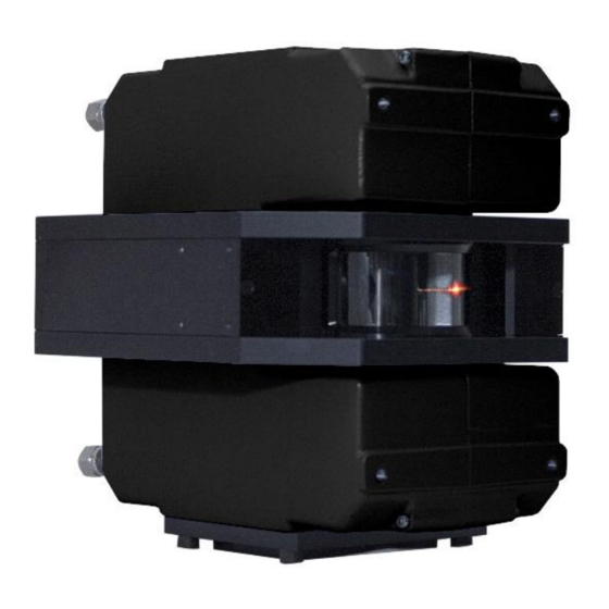
MP Series Users Manual, Rev. 1.0, Apr 2021 1 Description The MP infrared thermal linescanner is designed for use in highly demanding industrial environments and provides accurate temperature images of moving objects. This multi-point measurement is achieved by a rotating optical system, which collects infrared radiation at up to 1024 points within a 90º... -
Page 13: Figure 1-2: Principal Structure Of The Linescanning System
Description Measurement Specification Figure 1-2: Principal Structure of the Linescanning System Standard PC running DTDP Software Linescanner Ethernet Process... - Page 14 MP Series Users Manual, Rev. 1.0, Apr 2021 The following linescanner model variants are available: – – – – – – Series: Frequency: Spectral: Connector: Protocol: Data Points: Air Purge: Certificate: Linescanner 150 = 150 Hz 0 = M12 plug...
-
Page 15: Technical Data
Technical Data Measurement Specification 2 Technical Data 2.1 Measurement Specification Temperature Range MP150-3M 200 to 1500°C (392 to 2732°F) MP300-3M 250 to 1500°C (482 to 2732°F) MP150-2M 350 to 1500°C (662 to 2732°F) MP300-2M 400 to 1500°C (752 to 2732°F) MP150-1ML 600 to 1500°C (1112 to 2732°F) MP300-1ML... - Page 16 MP Series Users Manual, Rev. 1.0, Apr 2021 1024 pixel @ 80 Hz scan rate Scan Angle (FOV) All models 90°...
-
Page 17: Optical Specifications
Technical Data Optical Specifications 2.2 Optical Specifications Optical Resolution Measurement Resolution (90% energy) 200:1 (IFOV = 5 mrad) 200:1 (IFOV = 5 mrad) 200:1 (IFOV = 5 mrad) 200:1 (IFOV = 5 mrad) Hot Spot Detection (50% energy) 600:1 (IFOV = 1.7 mrad) 600:1 (IFOV = 1.7 mrad) 600:1 (IFOV = 1.7 mrad) 600:1 (IFOV = 1.7 mrad) -
Page 18: Far Focus
MP Series Users Manual, Rev. 1.0, Apr 2021 2.2.1.2 Far Focus Figure 2-2: Optical Diagrams Far Focus... -
Page 19: Optical Resolution Over Scan Rate
Technical Data Optical Specifications 2.2.2 Optical Resolution over Scan Rate Figure 2-3: Measurement Resolution depending on Scan Rate Figure 2-4: Hot Spot Detection depending on Scan Rate... -
Page 20: Electrical Specifications
MP Series Users Manual, Rev. 1.0, Apr 2021 2.3 Electrical Specifications Power 24 VDC ± 25%, 1 A Ethernet Connection M12 socket, 4 wires (full duplex) 100 MBit/s, 100BASE-TX / IEEE 802.3u, Auto-Negotiation electrically isolated from power supply Addressing fixed IP address... -
Page 21: Environmental Specifications
Technical Data Environmental Specifications 2.4 Environmental Specifications Ingress Protection IP65 (IEC 60529) Ambient Operating Temperature 0 to 50°C (32 to 122°F) without cooling max. 180°C (356°F) with integrated water cooling (Standard) Internal Operating Temperature Scanner 0 to 60°C (32 to 140°F) Laser automatic switch off at <... -
Page 22: Dimensions
MP Series Users Manual, Rev. 1.0, Apr 2021 2.5 Dimensions Figure 2-5: Dimensions and Mounting Locations All mounting threads are 4x M6 8 mm (0.31) deep (front side, upside, below) Air purge connections ISO 228 G⅛“ outer 5 mm (.2 in) ... -
Page 23: Scope Of Delivery
Technical Data Scope of Delivery 2.6 Scope of Delivery The scope of delivery includes the following: • Linescanner • Operating instructions (also included as PDF file on the data carrier) • DataTemp DP Software (lite version) • Protocol manual as PDF file on the data carrier •... -
Page 24: Basics
MP Series Users Manual, Rev. 1.0, Apr 2021 3 Basics 3.1 Measurement of Infrared Temperature All surfaces emit infrared radiation. The intensity of this infrared radiation changes according to the temperature of the object. Depending on the material and surface properties, the emitted radiation lies in a wavelength spectrum of approximately 1 to 20 µm. -
Page 25: Environment
Environment Ambient Temperature 4 Environment The linescanner complies with ingress protection IP65 and is therefore dust and splash resistant. The linescanner’s window is made of a material that is resistant to thermal stress. 4.1 Ambient Temperature Without water cooling, the linescanner is designed for ambient operating temperatures between 0 to 50°C (32 to 122°F). -
Page 26: Installation
MP Series Users Manual, Rev. 1.0, Apr 2021 5 Installation Risk of Personal Injury When this instrument is being used in a critical process that could cause property damage and personal injury, the user should provide a redundant device or system that will initiate a safe process shutdown in the event that this instrument should fail. -
Page 27: Mounting
Installation Mounting Figure 5-1: Scan Line Width L and Distance to Target D 5.3 Mounting The linescanner can be installed as follows: • on a tripod with a standard 1/4-20 UNC (photo equipment) thread. This type of setup requires the tripod mounting plate (A-MP-MP, available as accessory) and is recommended if the linescanner is to be used only for temporary or mobile measurements. -
Page 28: Laser
MP Series Users Manual, Rev. 1.0, Apr 2021 5.5 Laser The built-in laser sighting function allows fast and precise aiming at small or rapidly moving targets, or targets passing at irregular intervals. The laser is specially aligned with the scan line of the linescanner. A small, bright red laser line shows you the center of the scanned line, not the size of the spots being measured. -
Page 29: Water Cooling
Installation Water Cooling 5.6 Water Cooling The linescanner is equipped with integrated stainless-steel pipes for water cooling. These pipes are embedded in the cast aluminum housing. The water cooling system enables the linescanner to be installed in ambient temperatures up to 180°C (356°F). Maximum pressure for the cooling fluid is 15 bar (218 PSI). Only filtered water should be used in order to reduce the risk of clogging at the hose couplings. -
Page 30: Table 5-2: Minimum Device Temperatures [°C/°F]
MP Series Users Manual, Rev. 1.0, Apr 2021 Table 5-2: Minimum device temperatures [°C/°F] Relative Humidity [%] 100/ Example: Ambient temperature = 50°C Relative humidity = 40 % Minimum device temperature = 30°C The use of lower temperatures is at your own risk! The use of a thermostat is strongly recommended, see section 7.5... -
Page 31: Air Purge Collar
Installation Air Purge Collar 5.7 Air Purge Collar The air purge system produces a laminar air flow that protects the linescanner window from dust, moisture, and vapor. The air flows from the couplings through the walls of the housing and through side slits near the scanner’s window. -
Page 32: Power Supply
MP Series Users Manual, Rev. 1.0, Apr 2021 5.8 Power Supply The linescanner requires a nominal 24 VDC power supply, 18 VDC minimum. To insure that sufficient voltage is supplied to the linescanner, it is necessary to define the gage and the length of the power cable to determine the resistance and the voltage drop. -
Page 33: Ethernet
Installation Ethernet 5.9 Ethernet The linescanner can communicate via Ethernet interface or RS485. During system configuration the user selects either Ethernet or RS485. You cannot use Ethernet and RS485 communications for the data transfer at the same time! The Ethernet connection between linescanner and the PC has a maximum speed of 100 MBit/s and permits real- time data transfer for all temperature pixels. -
Page 34: Scanner Address Changing
MP Series Users Manual, Rev. 1.0, Apr 2021 The current settings for the IP address and the netmask of the PC can be asked with the command <ipconfig> in a Command Prompt window! Figure 5-3: Command Prompt For the example above, the IP address of the PC is 193.221.142.103. The subnet address is 193.221.142, the host address is 103. - Page 35 Installation Ethernet IP<NewScannerIPAddress> • With changing the IP address for the scanner you will immediately loose the connection, so you have to restart further Telnet session using address scanner: telnet <NewScannerIPAddress> <Port> • Save the new IP address permanentely in the scanner with the command: •...
-
Page 36: Pc Network Adapter
MP Series Users Manual, Rev. 1.0, Apr 2021 5.9.4 PC Network Adapter The network adapter on the PC side can be configured as following: Go to <Start> <Settings> <Network & Internet> <Status> <Change Connection Properties> Under <IP Settings> <IP assignment> click on <Edit>... - Page 37 Installation Ethernet Close the dialog box by pressing on <Save>.
-
Page 38: Inputs And Outputs
MP Series Users Manual, Rev. 1.0, Apr 2021 5.10 Inputs and Outputs In addition to the communication interfaces, the linescanner is also equipped with the following: • three active analog current outputs • an alarm output (potential-free relay contacts) •... -
Page 39: Table 5-4: Current Outputs, 4 Pins
Installation Inputs and Outputs Table 5-4: Current Outputs, 4 pins Description Color IGND common ground connection for all current outputs, brown, pink, gray electrically isolated to the GND ground OUT1 current output 1 yellow OUT2 current output 2 green OUT3 current output 3 white shield... -
Page 40: Operation
MP Series Users Manual, Rev. 1.0, Apr 2021 6 Operation 6.1 Target Viewing The relationship between scan rate, target speed, and target viewing time is shown in the figure below. Please note, the manufacturer provides the tool called “Spot Size Calculator” which allows the calculation distance between measured lines, see section 9.1... -
Page 41: Sectors
Operation Sectors 6.2 Sectors The linescanner is equipped with three analog outputs. Each output can be assigned to a ”sector” within the 90° scan angle. For each sector, the type of output (maximum, minimum, or mean value) can be selected. The output range can be configured for either 0 ... -
Page 42: Data Transfer Modes
MP Series Users Manual, Rev. 1.0, Apr 2021 6.3 Data Transfer Modes After each scan, the temperature values are transferred through the serial or the Ethernet interface to a computer. This computer will require either DataTemp software or custom software for data analysis. The data transfer can be achieved through one of two methods (selected by the user): •... -
Page 43: Accessories
Accessories Overview 7 Accessories 7.1 Overview A full range of accessories for various applications and industrial environments are available. Accessories include items that may be ordered at any time and added on-site. These include the following: Mechanical: • Mounting Plate (A-MP-MP) •... -
Page 44: Mounting Plate (A-Mp-Mp)
MP Series Users Manual, Rev. 1.0, Apr 2021 7.2 Mounting Plate (A-MP-MP) Figure 7-1: Mounting Plate for Tripod... -
Page 45: Adjustable Mounting Base (A-Mp-Rmb)
Accessories Adjustable Mounting Base (A-MP-RMB) 7.3 Adjustable Mounting Base (A-MP-RMB) Figure 7-2: Adjustable Mounting Base... -
Page 46: Tube Fittings (A-Mp-Fs-Xxx)
MP Series Users Manual, Rev. 1.0, Apr 2021 7.4 Tube Fittings (A-MP-FS-xxx) Description: 4x tube fittings - female adapter union (connects 6 mm outer diameter tube to conical thread Rc 1/8" (ISO7/1)) or 6 mm outer diameter tube to conical thread 1/8” NPT The tube fittings are available in two versions: •... -
Page 47: Reassembly Of The Tube Fittings
Accessories Tube Fittings (A-MP-FS-xxx) 7.4.2 Reassembly of the Tube Fittings You may disassemble and reassemble a Swagelok tube fitting as often as required. • Insert tubing with pre-swaged ferrules into the fitting body until the front ferrule seats. • Rotate the nut with a wrench to the previously pulled-up position. -
Page 48: Thermostat (A-Mp-Therm)
MP Series Users Manual, Rev. 1.0, Apr 2021 7.5 Thermostat (A-MP-THERM) The thermostat is an accessory which helps keep the housing temperature over the dew point thereby avoiding damage due to condensed water in the interior of the housing. The thermostat needs no further electrical installation. -
Page 49: Table 7-1: Thermostat Adjustment
Accessories Thermostat (A-MP-THERM) • Fix the cooling hoses as shown in the figure above. Ensure that the thermostat (arrow on the housing’s side) is installed according to the flow direction. Note: The fittings needed to connect the inner taper thread of the linescanner tube fitting (Rc 1/8") and the cooling hose of the Thermostat are not supplied as standard components! We recommend a Swagelok®... -
Page 50: Spare Window Kit (S-Mp-Wk-Xx)
MP Series Users Manual, Rev. 1.0, Apr 2021 7.6 Spare Window Kit (S-MP-WK-xx) The available spare window kits are listed in the table below. Each kit includes two windows and a gasket. For replacing the spare window see the procedure described in section 8.3 Window Replacment, page 59. -
Page 51: Power Supply Cable (A-Cb-Xx-Ps-Xx)
Accessories Power Supply Cable (A-CB-xx-PS-xx) 7.7 Power Supply Cable (A-CB-xx-PS-xx) The power supply cable comes with a three-socket female M16 connector, assigned to the scanner rear three pin male M16 connector. The corresponding end of the power supply cable is carried out as a pig tail, to connect to an external power supply device. -
Page 52: Ethernet Cable (A-Cb-Xx-M12-W04-Xx)
MP Series Users Manual, Rev. 1.0, Apr 2021 7.8 Ethernet Cable (A-CB-xx-M12-W04-xx) The Ethernet cable comes with a four-pin male M12 D-coded connector, assigned to the scanners rear female M12 connector. The corresponding end of the Ethernet cable is equipped with a general RJ45 snap-in connector. -
Page 53: Power Supply Din Rail (A-Ps-Din-24V)
Accessories Power Supply DIN Rail (A-PS-DIN-24V) 7.9 Power Supply DIN Rail (A-PS-DIN-24V) The DIN-rail mount industrial power supply delivers isolated DC power and provides short circuit and overload protection. Risk of Personal Injury To prevent electrical shocks, the power supply must be used in protected environments (cabinets)! Technical data: Protection class... -
Page 54: Rs485 Interface Kit (A-Mp-Conv-Serial-Xxx)
MP Series Users Manual, Rev. 1.0, Apr 2021 7.10 RS485 Interface Kit (A-MP-CONV-SERIAL-xxx) The RS232/485 interface provides a serial data transfer to the PC. However, the PC will have to be capable of communicating at a sufficiently high baud rate. Most standard PC’s communicate at speeds up to 115 kBaud which is capable of communication with the linescanner at a scan speed of 36 Hz and at 256 pixel per scan data sampling rate. -
Page 55: Rs485 Cable Extension
Accessories RS485 Interface Kit (A-MP-CONV-SERIAL-xxx) Power supply for the RS232/485 converter: Twisted pairs: 12 V To program the linescanner via its serial interface (see linescanner protocol manual), the serial interface settings needs to be: 8 data bits, no parity bit, 1 stop bit, no flow control Allowed baud rates:... -
Page 56: Fiber-Optic/Rj45 Converter (A-Con-Xfo-Xrj45)
MP Series Users Manual, Rev. 1.0, Apr 2021 7.11 Fiber-Optic/RJ45 Converter (A-CON-xFO-xRJ45) The Fiber-Optic/RJ45 Converter is an industrial Ethernet switch with Ethernet and fiber optic ports. The converter is DIN-rail or wall mountable: • 1x Fibre optic, 1x Ethernet (A-CON-1FO-1RJ45) •... -
Page 57: Maintenance
Maintenance Troubleshooting 8 Maintenance Our sales representatives and customer service staff are always at your disposal for questions regarding applications, calibration, repair, and solutions to specific problems. Please contact your local sales representative if you need assistance. In many cases, problems can be solved over the telephone. If you need to return equipment for servicing, calibration or repair, please contact our Service Department before shipping. - Page 58 MP Series Users Manual, Rev. 1.0, Apr 2021 Checkpoint Possible Cause / Solution • Disable the PC network adapter temporarily: <Start> <Settings> <Control panel> <System> <Hardware> <Device Manager> <Network adapters> • Switch on/off the scanner’s power. • Software is not to be launched during the initialization time of the scanner (about 120 s).
-
Page 59: Window Cleaning
Maintenance Window Cleaning 8.2 Window Cleaning The linescanner’s window must be kept as clean as possible. Any foreign matter on the window will affect the accuracy of the measurements. Take care when cleaning the window as it can easily be scratched. Please observe the following guidelines: •... - Page 60 MP Series Users Manual, Rev. 1.0, Apr 2021 Check for even tension of the film. Remove the film and repeat the steps if there are wrinkles on the film! Install the window assembly on the housing by alternating between the four screws. Do not over-tighten!
-
Page 61: Appendix
Appendix Spot Size Calculator 9 Appendix 9.1 Spot Size Calculator It is important that the sensor is mounted at a distance from the target, sufficient to be able to “see” the entire area of interest. For this reason, the manufacturer provides a field of view calculating software called “Spot Size Calculator”, which allows the calculation of the resulting spot size for a given sensor model and based on a specific mounting distance. -
Page 62: Determination Of Emissivity
MP Series Users Manual, Rev. 1.0, Apr 2021 9.2 Determination of Emissivity Emissivity is a measure of an object’s ability to absorb and emit infrared energy. It can have a value between 0 and 1.0. For example, a mirror has an emissivity of < 0.1, while the so-called blackbody reaches an emissivity value of 1.0. - Page 63 Appendix Typical Emissivity Values Table 9-1: Typical Emissivity Values for Metals Metals Emissivity Material 1 µm 1.6 µm 2.3 µm Aluminum Unoxidized 0.1-0.2 0.02-0.2 0.02-0.2 Oxidized 0.2-0.4 Alloy A3003, Oxidized Roughened 0.2-0.8 0.2-0.6 0.2-0.6 Polished 0.1-0.2 0.02-0.1 0.02-0.1 Brass Polished 0.1-0.3 0.01-0.05 0.01-0.05...
- Page 64 MP Series Users Manual, Rev. 1.0, Apr 2021 Metals Emissivity Material 1 µm 1.6 µm 2.3 µm Monel (Ni-Cu) 0.2-0.6 0.2-0.6 Oxidized Nickel Oxidized 0.8-0.9 0.4-0.7 0.4-0.7 Electrolytic 0.2-0.4 0.1-0.3 0.1-0.2 Platinum Black 0.95 0.95 Silver 0.02 0.02 Steel Cold-Rolled 0.8-0.9...
- Page 65 Appendix Typical Emissivity Values Table 9-2: Typical Emissivity Values for Non-Metals ETALS Emissivity Material 1 µm 1.6 µm 2.3 µm Asbestos Asphalt Basalt Carbon Unoxidized 0.8-0.95 0,8-0,9 Graphite 0.8-0.9 0.8-0.9 Carborundum 0.95 Ceramic 0.8-0.95 Clay 0.8-0.95 Coke 0.95-1.00 0.95-1.00 0.95-1.00 Concrete 0.65 Cloth...
Need help?
Do you have a question about the MP Series and is the answer not in the manual?
Questions and answers