Table of Contents

Subscribe to Our Youtube Channel
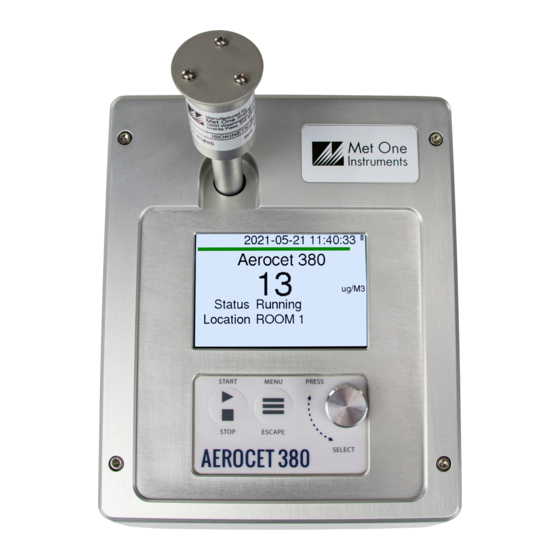
Related Manuals for Met One Instruments AEROCET-380


Summary of Contents for Met One Instruments AEROCET-380
- Page 1 AEROCET-380 Particulate Monitor Operation Manual Revision A Met One Instruments, Inc Corporate Sales & Service: 1600 NW Washington Blvd. Grants Pass, OR 97526 Tel (541) 471-7111 Fax (541) 471-7116 www.metone.com service@metone.com...
- Page 2 Page 1 AEROCET-380 Operation Manual Rev A...
- Page 3 Copyright Notice AEROCET-380 Manual © Copyright 2022 Met One Instruments, Inc. All Rights Reserved Worldwide. No part of this publication may be reproduced, transmitted, transcribed, stored in a retrieval system, or translated into any other language in any form by any means without the express written permission of Met One Instruments, Inc.
-
Page 4: Table Of Contents
About This Manual ........................5 Technical Service ........................5 About the AEROCET-380 ......................6 Laser Radiation Safety and Conformity ..................6 AEROCET-380 Specifications ....................7 AEROCET-380 SETUP and STARTUP ..............8 Unpacking ..........................8 Layout............................9 Default Settings ........................10 Initial Operation ........................10 User Interface ....................... - Page 5 10.1 Suggested Periodic Maintenance Intervals................29 10.2 Flow Audit and Calibration ....................... 29 10.3 PUMP and PURGE Filter Changes ..................29 10.4 Factory Service ........................30 10.5 Flash Upgrade .......................... 30 Troubleshooting ....................31 Accessories ......................32 Page 4 AEROCET-380 Operation Manual Rev A...
-
Page 6: Introduction
1.1 About This Manual This document is organized with the most important information grouped together for easy reference by the user. All AEROCET-380 owners and operators should read and understand the sections on installation, setup, and field calibrations. Other sections that provide in-depth information on subjects such as theory, diagnostics, accessories, and alternate settings provide valuable information which should be consulted as needed. -
Page 7: About The Aerocet-380
Laser Light Scatter System Sample air is drawn into the AEROCET-380 and through the laser optical module, where the particulate in the sample air stream scatters the laser light through reflective and refractive properties. This scattered light is collected onto a photodiode detector at a near-forward angle, and the resulting electronic signal is processed to determine a continuous, real-time measurement of airborne particulate mass concentrations. -
Page 8: Aerocet-380 Specifications
24 Months typical, under continuous use in normal ambient air. Unit Weight: 2.3kg (5.1lbs) 21.6cm high, 15.2cm wide, 21.0cm deep (8.5” x 6.0” x 8.25”) Unit Dimensions: Specifications may be subject to change without notice. Page 7 AEROCET-380 Operation Manual Rev A... -
Page 9: Aerocet-380 Setup And Startup
The following sections cover unpacking, layout and performing a test run to verify operation. 2.1 Unpacking When unpacking a new AEROCET-380, verify that the contents are undamaged. Any damages incurred to the equipment during shipping are the responsibility of the carrier. If any damage to the shipment is noticed before unpacking, a claim must be filed with the commercial carrier immediately. -
Page 10: Layout
Figure 2-1 - AEROCET-380 Layout Component Description Power Switch Switch that turns the AEROCET-380 on or off. Press up to turn on and press down to turn off. Charging Jack Input jack for the battery charger. This connection charges the internal battery pack and provides continuous operating power for the unit. -
Page 11: Default Settings
K Factor 2.4 Initial Operation Before operating the AEROCET-380 for the first time, it is recommended that the unit be fully charged. Information regarding charging the battery is found in Section 6 of this manual. Complete the following steps to verify proper operation. -
Page 12: Operation
4.2 Power Up AEROCET-380 power is controlled by a switch located on the back of the unit. Press the power switch to the on position (towards the top of the case) to power up the unit. The first screen shown on power up is the Startup screen. This screen briefly displays the company logo before loading the Operate Screen. -
Page 13: Sample Status
4.3.2 Sample Status The top of the Operate screen displays the status of the AEROCET-380 while the unit is sampling. A status bar fills with green as time progresses. The status line below the sample mass data indicates whether the unit is purging, zeroing, or sampling. The following table... -
Page 14: Main Menu
Rotate the dial to increment or decrement a value. the dial Press the dial to select the next character. Press the dial for all remaining characters to save the value or to cancel and return to the previous screen. ESCAPE Page 13 AEROCET-380 Operation Manual Rev A... -
Page 15: Sample Setup
A span check then occurs after the zero calibration if it is enabled. This sequence is repeated at the interval selected for the Zero Period. Page 14 AEROCET-380 Operation Manual Rev A... -
Page 16: Span Test
Figure 5-3 - Toolbox Screen 5.3.1 Memory The AEROCET-380 can store up to 15,000 sample records in its memory. For instructions on viewing stored data, see Section 4.3.3. Because this memory is circular, once all records are full, any new samples taken will overwrite the oldest stored sample data. -
Page 17: K-Factor
PSL spheres in clean filtered air for both calibration and certification of performance specifications. Calculate the K-Factor as the reference concentration divided by the AEROCET-380 light scatter concentration over the same time period. For example, if the reference total concentration was 51 μg/m... -
Page 18: Display
The Flow Calibration is used for field audits or calibrations of the sample flow measurement. Remove the TSP cap and any cyclones from the Aerocet-380 inlet tube, and then connect the top of inlet tube to the outlet of a traceable flow meter using a length of appropriate flexible tubing. -
Page 19: Initial Setup
Use this if difficulty is encountered during the calibration. Press ESCAPE to escape without changes. Note: To audit the AEROCET-380 flow rate without changing the calibration, simply compare the flow value to a traceable standard and record the results. If the SET key is not selected, then no flow calibrations are affected. -
Page 20: Clock
Press the dial to select each character. All 7 characters must be selected to save the location ID. It is suggested to use spaces for a location with less than 7 characters. Figure 5-9 - Locations Screen Page 19 AEROCET-380 Operation Manual Rev A... -
Page 21: Wifi Discovery
Once the scan completes the WiFi connection credentials will display on the screen. If the unit was never set up for WiFi a time out message will appear. Press escape to exit this screen. Figure 5-11 - WiFi Configuration Results (left) and Time Out Screen (right) Page 20 AEROCET-380 Operation Manual Rev A... -
Page 22: About Screen
To charge the battery, connect the battery charger to an AC power outlet and the DC plug to the socket on the back of the AEROCET-380. The battery charger is universal and will work with power line voltages of 100 to 240 volts, 50 to 60 Hz. The battery charger LED will be Red while charging and the LED will turn Green when the battery is fully charged. -
Page 23: Wifi Configuration And Setup
7 WiFi Configuration and Setup The WiFi on the AEROCET-380 will need to be connected to the local network where it is used. This section covers the initial setup and configuration of the WiFi. Valid credentials for a WiFi network in range and either a computer or smartphone that can connect to that network must be used to configure the AEROCET-380. - Page 24 Figure 7-3 - WiFi Station Configuration 6. After the AEROCET-380 has connected to the network it will show the internal IP address it was assigned from the network. Click the IP address to automatically navigate to the new IP address. The dock will now automatically shut off its hosted network.
- Page 25 WiFi Baud of the measurement device. Default WiFi Baud is 115200. Figure 7-5 - Microcontroller Console 10. You can now communicate with the device over WiFi using serial commands. A TCP/IP connection is made using the assigned IP through Port 23. Page 24 AEROCET-380 Operation Manual Rev A...
-
Page 26: Serial Communications
9.1 Commands The AEROCET-380 provides serial commands for accessing stored data and settings. All commands are terminated by a carriage return. These commands are not case sensitive. The following table lists the available commands. These commands are available via USB, RS-485, and WiFi hardware interfaces. -
Page 27: Serial Commands
Get the data log channel descriptors CRC STPER Self Test Period. STPER 0=1 HR, STPER 1=2 HR, STPER 2=12 HR, STPER 3=24 HR DISPTO Manual Display Timeout. DISPTO 0=None, DISPTO 1=1-min, DISPTO 2=5-min, DISPTO 3=10-min Page 26 AEROCET-380 Operation Manual Rev A... -
Page 28: Output
Low Battery 9.3 MODBUS Communication The AErocet-380 supports MODBUS communications protocol with any serial connection that is set in the Modbus Setup in Section 5.4.2. The serial transmission is RTU mode. The following MODBUS registers are used to access various readings. -
Page 29: Modbus 3X Registers
Status Word MB_Last_Location 2004 string Last Record Location string MB_Avg_Conc 2008 float Average Concentration MB_Avg_Flow 2010 float Average Flow MB_Avg_AT 2012 float Average Temperature MB_Avg_BP 2014 float Average BP MB_Avg_BV 2016 float Battery Voltage Page 28 AEROCET-380 Operation Manual Rev A... -
Page 30: Maintenance
10 Maintenance This section provides information about routine maintenance of the AEROCET-380. The case of the AEROCET-380 should never be removed or opened for any reason. Opening or removing the case of the AEROCET-380 voids the warranty and may result in exposure to laser radiation, which can cause eye injury. -
Page 31: Factory Service
Refer to section 1.2 to contact Met One for technical assistance and/or factory services. 10.5 Flash Upgrade AEROCET-380 is firmware upgradeable via the USB C serial connection using a Met One Instruments flash burn program. The flash program must be provided by Met One Instruments, Inc. -
Page 32: Troubleshooting
The following section covers some common failure symptoms, causes and solutions. The AEROCET-380 case should never be removed or opened for any reason. Opening or removing the case will void the warranty and may result in exposure to laser radiation, which can cause eye injury. -
Page 33: Accessories
12 Accessories The following is a list of included accessories and replacement parts for the AEROCET-380. Replacement Parts (not included) Description Part Number Graphic Purge Filter Holder, Black Aluminum 80588 Pump Filter Holder, Black Aluminum 80588-1 Purge Air Filter, 0.01 micron...
Need help?
Do you have a question about the AEROCET-380 and is the answer not in the manual?
Questions and answers